
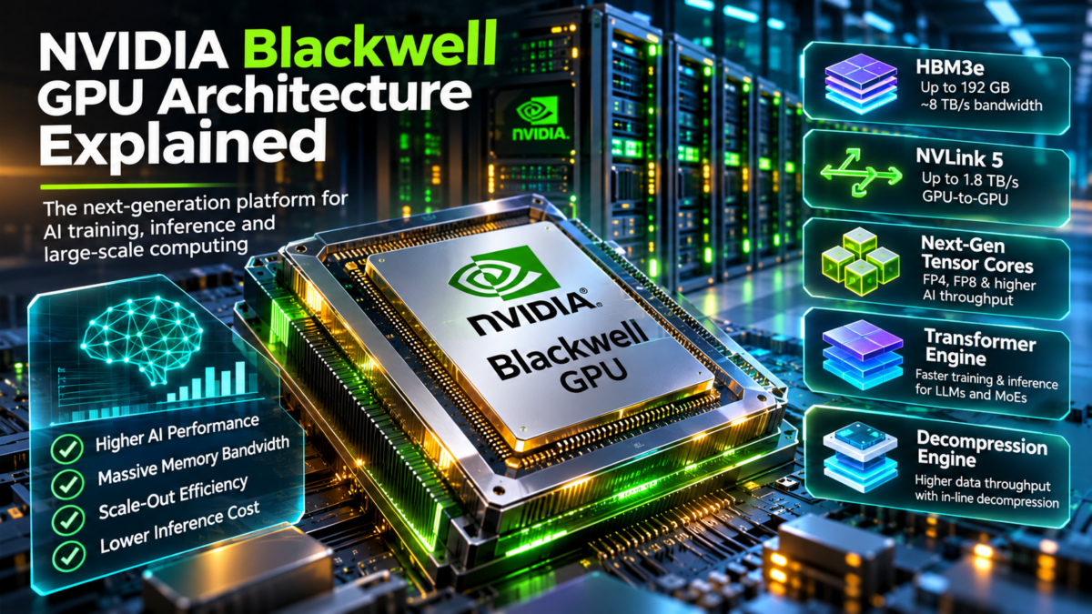
NVIDIA Blackwell GPU Architecture Explained
Modern AI infrastructure is no longer defined by GPU compute alone. NVIDIA Blackwell combines advanced GPU silicon, high-bandwidth memory, specialized Transformer Engine acceleration, high-speed GPU interconnects and rack-scale networking into an integrated architecture for training and serving large AI models. Explore the engineering layers that make these systems work.
Blackwell GPU Compute
Why Blackwell Changes AI Infrastructure Design
Traditional infrastructure architecture often treats processors, memory, networking and storage as separate resources. Large AI workloads expose the limitations of that approach. Model training requires coordinated computation across accelerators, while inference must balance memory capacity, token throughput, request latency and serving efficiency.
Blackwell-based systems address these demands through a combination of GPU compute, high-bandwidth HBM3e memory, high-speed NVLink connectivity, and integration with external networking fabrics. In Grace Blackwell configurations, the architecture also connects NVIDIA Grace CPUs with Blackwell GPUs through a high-bandwidth coherent interconnect.
The engineering challenge is therefore broader than selecting the fastest GPU. Architects must understand data placement, memory bandwidth, communication topology, distributed execution, power delivery, cooling and observability. These relationships determine whether expensive accelerator infrastructure delivers useful application performance.
Explore the NVIDIA Blackwell Architecture
Navigate nine engineering layers — from the dual-die Blackwell GPU to rack-scale AI networking, distributed training, inference and production troubleshooting. Select any architecture node to reveal its engineering annotation.
Inside the NVIDIA Blackwell GPU Architecture
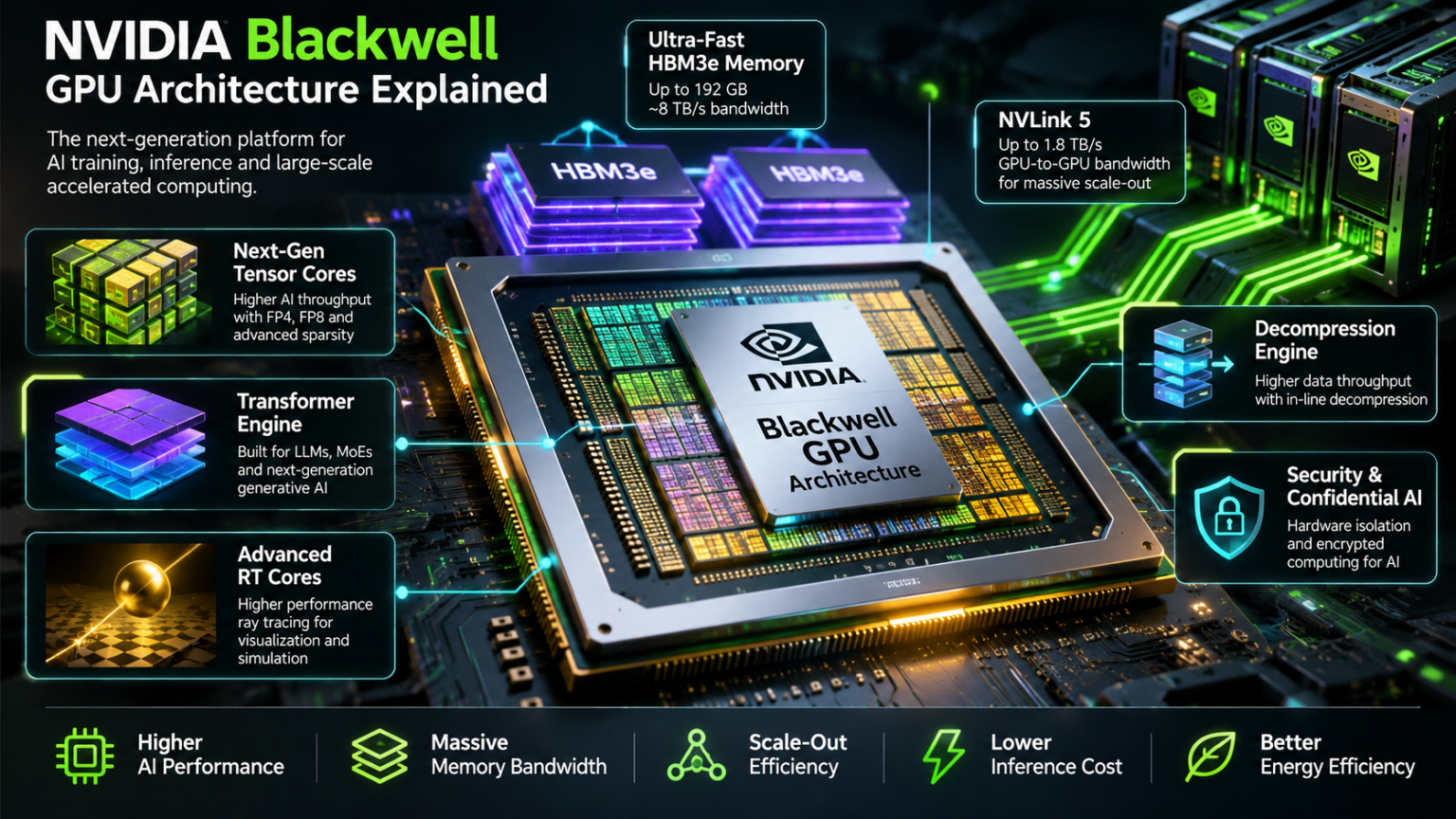
NVIDIA Blackwell represents a major evolution in accelerated computing architecture. Rather than treating the GPU as an isolated processor, Blackwell combines advanced silicon packaging, high-bandwidth memory, high-speed interconnects and scalable system integration to support demanding artificial intelligence workloads.
At the center of the B200 architecture are two GPU dies connected by a high-bandwidth die-to-die interface. The dies operate together as one logical GPU, enabling a large compute design while retaining the advantages of multi-die manufacturing.
GPU Die A
One of two large GPU dies in the Blackwell GPU design. The dies are connected through a high-bandwidth interface and operate together as a unified accelerator.
1. Multi-Die GPU Architecture
Blackwell uses two GPU dies connected through a high-bandwidth interface. This approach allows NVIDIA to build a large logical accelerator without manufacturing the entire design as a single monolithic die.
Each die contributes compute resources to the overall GPU. The architecture is designed to make the combined device function as one accelerator from the perspective of supported software workloads.
Multi-die integration introduces engineering challenges around communication latency, bandwidth, physical packaging, power distribution and thermal management. These must be addressed to ensure that the combined GPU behaves efficiently under large workloads.
2. Compute Hierarchy and AI Execution
GPU execution is organized around many parallel processing resources. Streaming Multiprocessors execute groups of threads, while specialized Tensor Cores accelerate matrix operations commonly used in machine learning.
Large language models repeatedly perform matrix multiplication, attention and other numerical operations. Their efficiency depends on how well these operations map to the GPU compute hierarchy and how effectively data is supplied from memory.
The Blackwell Transformer Engine adds support for advanced reduced-precision computation, including FP4-related capabilities, to improve AI performance where model accuracy and software compatibility permit.
Engineering principle: A GPU's theoretical compute capability is only one part of application performance. Memory bandwidth, data locality, kernel execution efficiency and communication overhead can determine the actual throughput achieved by training and inference workloads.
3. Understanding the Blackwell System Hierarchy
The Blackwell name appears across several NVIDIA products and integration levels. These should not be treated as interchangeable hardware components.
B200 GPU
Blackwell GPU compute architecture with HBM memory, designed for integration into accelerated computing systems.
GB200
Combines one NVIDIA Grace CPU with two Blackwell GPUs, using NVLink-C2C for high-bandwidth CPU–GPU connectivity.
GB200 NVL72
Rack-scale design integrating 72 Blackwell GPUs and 36 Grace CPUs with an NVLink switch fabric.
4. Architecture Comparison
| Architecture | Compute integration | Interconnect emphasis | Engineering focus |
|---|---|---|---|
| B200 GPU | Two Blackwell GPU dies forming one logical GPU | Internal die interconnect and GPU I/O | Compute, HBM bandwidth and accelerator utilization |
| GB200 Superchip | One Grace CPU and two Blackwell GPUs | NVLink-C2C and GPU interconnection | CPU–GPU memory and system integration |
| GB200 NVL72 | 36 Grace CPUs and 72 Blackwell GPUs | Rack-scale NVLink switching | Collective communication, power, cooling and rack-scale design |
5. Implications for Infrastructure Architects
Designing a Blackwell deployment requires an understanding of the entire compute system. At the accelerator level, engineers examine memory capacity, precision support and compute efficiency. At the server level, they consider CPU integration, accelerator placement, host connectivity and I/O bandwidth.
At rack scale, the design expands to include GPU-to-GPU communication, NVSwitch topology, external network fabrics, power distribution, liquid cooling and fault isolation. These concerns are particularly important when large AI models are distributed across many accelerators.
The key architectural distinction is between scale-up, which connects accelerators into a tightly coupled compute domain, and scale-out, which connects multiple systems through external networks such as Ethernet or InfiniBand.
Production troubleshooting perspective: Low GPU utilization does not automatically indicate insufficient compute capacity. The bottleneck may originate in memory access, data loading, communication synchronization, network congestion, CPU processing or workload scheduling. Effective diagnosis requires telemetry across the complete system.
Technical reference: NVIDIA Blackwell architecture documentation and NVIDIA GB200 NVL72 system architecture. Performance characteristics and memory configurations depend on the specific product and platform.
Blackwell GPU Architecture Explorer
Explore the hierarchy of NVIDIA Blackwell infrastructure. Switch between a B200 GPU architecture view and a GB200 Grace Blackwell Superchip view. Select any component to investigate its engineering role and key specifications.
NVIDIA B200 GPU
Blackwell combines two GPU dies into one unified accelerator, providing high-throughput compute, HBM3e memory and high-speed GPU interconnects for AI training and inference.
How Blackwell Accelerates AI Computation
Blackwell's AI performance comes from the interaction between massively parallel GPU execution, specialized Tensor Cores, high-bandwidth memory and the second-generation Transformer Engine. Understanding this compute pipeline is essential when evaluating training throughput, inference latency, numerical precision and GPU utilization.
Transformer workloads are dominated by large matrix operations, attention calculations and repeated movement of model data. Blackwell introduces additional reduced-precision capabilities, including FP4 support, that can improve effective throughput and memory efficiency when applied appropriately.
HBM3e Data Supply
High-bandwidth memory supplies model weights, activations and intermediate data to GPU execution resources. Effective performance depends on the relationship between memory traffic and computational demand.
1. Streaming Multiprocessors
Streaming Multiprocessors, or SMs, are fundamental execution units within NVIDIA GPU architectures. They schedule and execute groups of threads, coordinate execution resources and provide access to registers, shared memory and specialized processing units.
In AI workloads, SMs execute the kernels that implement matrix multiplication, attention, normalization, activation functions and other numerical operations.
Kernel performance depends on occupancy, register usage, memory access patterns, instruction scheduling and the ability to keep execution resources supplied with useful work.
2. Tensor Cores and Matrix Operations
Tensor Cores accelerate matrix-oriented arithmetic, which forms the computational foundation of modern neural networks. Matrix multiplication appears throughout transformer models, including projection layers, feed-forward networks and attention calculations.
Specialized matrix acceleration enables much higher throughput than relying exclusively on general-purpose arithmetic for suitable operations.
However, peak Tensor Core performance depends on supported data types, matrix dimensions, software kernels and efficient movement of operands through the GPU memory hierarchy.
Engineering principle: A GPU may have enormous theoretical matrix-compute throughput while an application achieves only a fraction of it. Poor tensor shapes, insufficient batching, memory bandwidth limitations, synchronization and kernel launch overhead can all reduce effective utilization.
3. Transformer Engine and Numerical Precision
The Blackwell Transformer Engine supports precision-aware acceleration for transformer workloads. Its capabilities include support for lower-precision formats such as FP8 and FP4, allowing compatible AI operations to use fewer bits for numerical representation.
Reducing precision can decrease memory requirements and improve computational throughput. However, lower precision changes the range and accuracy of numerical values, so successful deployment depends on scaling strategies, quantization methods, model characteristics and validation.
4. Precision Trade-offs in AI Infrastructure
| Format | Bits per value | Potential benefit | Engineering consideration |
|---|---|---|---|
| FP32 | 32 | Higher numerical precision | Greater storage and bandwidth demand |
| BF16 | 16 | Reduced memory use with useful numerical range | Precision and convergence validation |
| FP8 | 8 | Lower data footprint and accelerated matrix operations | Scaling, supported kernels and accuracy |
| FP4 | 4 | Very compact representation and high potential compute efficiency | Quantization error, model support and validation |
Actual compute speedups are workload-dependent. Numerical formats alone do not determine end-to-end application throughput.
5. Training and Inference Compute Characteristics
Training involves forward propagation, backward propagation and parameter updates. It requires significant compute capacity and often maintains additional intermediate state for gradient calculation and optimization.
Inference executes a trained model to generate predictions or tokens. For large language models, the prefill phase processes input tokens and can be compute-intensive, while token-by-token decoding often becomes constrained by memory bandwidth, KV cache access and request concurrency.
These differences mean that GPU configuration, batch size, numerical precision and scheduling policies should be selected according to the actual workload rather than theoretical peak accelerator performance alone.
Production troubleshooting: Investigate low Tensor Core utilization by examining kernel profiles, matrix shapes, GPU occupancy, memory throughput, precision configuration and application batching. Correlate GPU metrics with end-to-end workload latency before attributing poor performance to the accelerator hardware.
6. Engineering Takeaway
Blackwell compute performance emerges from a coordinated architecture: HBM supplies data, Streaming Multiprocessors execute kernels, Tensor Cores accelerate matrix arithmetic and the Transformer Engine enables supported precision optimizations. The practical objective is to maximize useful AI throughput while maintaining acceptable numerical accuracy, memory efficiency and service latency.
Blackwell Transformer Engine Simulator
Investigate how tensor precision changes storage requirements, matrix computation and numerical behaviour. Configure a workload, select a precision format and trace its execution through a conceptual Blackwell Tensor Core pipeline.
Interactive compute pipeline
Input storage comparison
BF16 precision
Engineering interpretation
HBM3e Memory, Bandwidth and AI Model Data
GPU compute performance depends on the ability to supply processing resources with data. NVIDIA Blackwell uses High Bandwidth Memory, or HBM3e, to provide large memory capacity and extremely high bandwidth close to the GPU compute dies.
For modern AI workloads, the memory subsystem must accommodate model weights, intermediate activations, attention KV caches and temporary execution buffers. Memory capacity determines which workloads fit, while bandwidth and access patterns influence how quickly those workloads execute.
HBM3e Memory Stacks
HBM3e uses vertically stacked memory dies connected through advanced packaging technology. This architecture provides high aggregate bandwidth and substantial capacity close to the GPU.
1. How HBM3e Works
High Bandwidth Memory uses multiple DRAM dies stacked vertically and connected using advanced packaging technologies. The memory stacks are integrated close to GPU compute resources, allowing a very wide memory interface and high aggregate throughput.
Compared with conventional memory architectures, HBM prioritizes bandwidth density and energy-efficient data movement over relatively short physical distances.
Blackwell uses HBM3e to support the large data footprints and intensive memory access patterns associated with transformer training and inference.
2. GPU Memory Consumers
AI workloads use GPU memory for several distinct purposes. Model weights store learned parameters, activations hold intermediate computation results, and temporary buffers support execution kernels and communication operations.
During autoregressive inference, the KV cache stores attention keys and values from previously processed tokens. Its size increases with the number of retained tokens and active sequences, subject to the model architecture and cache-management strategy.
Memory planning must account for all these consumers rather than considering model weights alone.
Engineering principle: A model fitting into GPU memory does not guarantee efficient execution. Available bandwidth, access patterns, batching, memory fragmentation and communication overhead can still limit useful throughput.
3. Interactive GPU Memory Allocation Explorer
Adjust the example model footprint and concurrent KV-cache allocation to see how memory pressure changes. This is a simplified capacity-planning exercise, not a live Blackwell GPU measurement.
4. Compute-Bound Versus Memory-Bound Workloads
A compute-bound workload is limited primarily by the rate at which the GPU can execute useful arithmetic. A memory-bound workload is limited by how quickly required data can be transferred from memory to processing resources.
Transformer prefill operations often perform substantial matrix computation and can achieve high arithmetic intensity. Autoregressive decoding, especially at low batch sizes, can be strongly influenced by the cost of reading model weights and accessing KV-cache data.
Increasing batch size may improve reuse of model weights and arithmetic efficiency, but it also increases memory consumption and can affect latency.
| Memory component | Purpose | Performance impact | Engineering investigation |
|---|---|---|---|
| Model weights | Store learned parameters | Capacity demand and repeated weight reads | Quantization, model partitioning and residency |
| Activations | Intermediate computation state | Training memory consumption | Checkpointing and execution strategy |
| KV cache | Retain attention state for inference | Concurrency, context length and decoding memory | Cache sizing, paging and eviction |
| Execution buffers | Temporary kernel and framework storage | Available headroom and allocation pressure | Allocator metrics and memory profiling |
| HBM bandwidth | Move data between memory and compute | Limits memory-intensive operations | Bandwidth utilization and kernel profiling |
5. Production Memory Troubleshooting
GPU out-of-memory conditions can arise even when model parameters appear to fit within the advertised memory capacity. Runtime allocations, KV-cache growth, temporary buffers, memory fragmentation and framework overhead must also be considered.
For performance investigations, correlate memory utilization with memory throughput, GPU compute utilization, request concurrency and application latency. High memory occupancy is not necessarily a fault; low available capacity becomes problematic when additional allocations cannot be satisfied or workload growth causes instability.
Where supported, model quantization, paged KV-cache management, activation checkpointing and distributed model partitioning can help address memory constraints. Each introduces trade-offs involving numerical accuracy, compute overhead, communication or complexity.
Architecture takeaway: GPU memory planning has two independent dimensions: capacity determines whether the working set fits, while bandwidth determines how quickly data-intensive operations can be supplied. Both must be evaluated alongside compute throughput and communication performance.
Illustrative capacity values are used in the interactive exercise. Actual Blackwell memory capacity and bandwidth depend on the specific accelerator and platform configuration.
HBM3e Memory Allocation & Bandwidth Explorer
Configure an AI workload and investigate how model weights, attention KV cache, activation memory and runtime allocations compete for limited GPU HBM capacity. Explore the relationship between memory footprint and bandwidth demand.
Interactive GPU memory map
Aggregated HBM capacity across selected GPUs. The diagram assumes idealised equal sharding of model and cache allocations.
HBM bandwidth model
Illustrative aggregate bandwidth ceiling for the selected GPU count.
Weights are estimated from parameter count and precision. KV cache uses an illustrative transformer configuration. Activations and runtime memory are approximations, not exact measurements from a deployed model.
Configure a workload to evaluate its HBM footprint.
Memory requirements depend on architecture, quantization, sequence length, concurrency and sharding strategy.
NVLink, NVSwitch and Rack-Scale GPU Fabrics
As AI models grow, a single GPU is often insufficient to provide the required compute capacity or memory footprint. Large-scale training and inference therefore depend on communication between multiple accelerators. NVIDIA NVLink and NVSwitch provide the high-bandwidth scale-up connectivity that allows groups of GPUs to operate as tightly coupled compute systems.
Blackwell introduces fifth-generation NVLink technology, supporting high-speed GPU communication and large NVSwitch-based domains. In GB200 NVL72 systems, the scale-up fabric connects 72 Blackwell GPUs into a rack-scale architecture designed for demanding AI workloads.
GPU-to-GPU Communication
Select a GPU to inspect its communication path through the conceptual NVSwitch fabric. NVLink enables high-bandwidth communication between accelerators within a scale-up domain.
1. Fifth-Generation NVLink
NVLink is NVIDIA's high-speed accelerator interconnect technology. It provides communication bandwidth beyond what conventional host I/O connections alone typically deliver, supporting frequent exchanges of data between GPUs.
Blackwell's fifth-generation NVLink provides up to 1.8 TB/s of aggregate bidirectional bandwidth per GPU in supported configurations. This bandwidth is important for model parallelism, distributed tensor operations and communication-intensive AI workloads.
NVLink bandwidth is not equivalent to application throughput. Effective performance depends on transfer size, communication patterns, synchronization, topology and software implementation.
2. NVSwitch Fabric Architecture
NVSwitch extends NVLink communication beyond simple direct GPU connections by providing switched connectivity among multiple accelerators. This enables large GPU communication domains with high aggregate bandwidth.
In rack-scale systems, multiple NVSwitch devices and physical links form the communication fabric. GPUs communicate through this infrastructure while collective communication libraries coordinate data exchange between participating devices.
NVSwitch is part of the scale-up fabric. External Ethernet or InfiniBand networks serve the different purpose of connecting servers and scale-up domains into larger distributed clusters.
Engineering distinction: NVLink is the high-speed communication interconnect, while NVSwitch provides switching across an NVLink fabric. NCCL and related communication software implement collective operations using the available topology. These are separate but complementary architectural layers.
3. GB200 NVL72 Rack-Scale Architecture
The GB200 NVL72 architecture combines 72 Blackwell GPUs and 36 NVIDIA Grace CPUs in a liquid-cooled rack-scale system. The GPUs are connected through a fifth-generation NVLink switching fabric to support large, tightly coupled AI workloads.
The NVL72 architecture is more than a collection of independent GPU servers. Its rack-scale interconnect, power infrastructure and liquid-cooling design are central parts of the system architecture.
4. Collective Communication and Model Parallelism
Distributed AI workloads frequently require communication patterns that involve many GPUs. Collective operations include All-Reduce, All-Gather, Reduce-Scatter and broadcast. These operations exchange or combine data across a group of participating accelerators.
For example, tensor parallelism may require All-Reduce or All-Gather operations between GPUs during neural network execution. Data parallelism often uses gradient synchronization, while pipeline parallelism transfers intermediate activations between processing stages.
The cost of collective communication depends on the number of GPUs, message size, communication algorithm and available fabric bandwidth.
| Operation | Purpose | Common AI use | Engineering concern |
|---|---|---|---|
| Point-to-point | Transfer data between selected GPUs | Pipeline stage communication | Latency and path utilization |
| All-Reduce | Combine values and distribute results | Gradient or tensor synchronization | Collective overhead and synchronization |
| All-Gather | Collect distributed data across participants | Tensor and parameter assembly | Aggregate traffic and memory usage |
| Reduce-Scatter | Reduce values and distribute partitions | Distributed training algorithms | Bandwidth and algorithm efficiency |
| Broadcast | Distribute data from one participant | Parameter or control-data distribution | Fan-out and transfer efficiency |
5. Scale-Up Versus Scale-Out Networking
Scale-up architectures connect accelerators within a high-bandwidth communication domain, typically using NVLink and NVSwitch. Scale-out architectures connect multiple compute nodes or scale-up domains through external networking fabrics.
Large AI clusters often use both approaches. The scale-up fabric handles tightly coupled accelerator communication, while the scale-out network connects systems for distributed training, data exchange and access to external infrastructure.
Understanding where traffic crosses from scale-up to scale-out is essential when diagnosing communication bottlenecks and designing efficient model placement strategies.
Production troubleshooting: When distributed AI performance deteriorates, investigate collective operation latency, GPU synchronization, NVLink errors, NVSwitch health, fabric bandwidth utilization and application communication patterns. Do not assume that low GPU utilization is caused by insufficient compute capacity.
6. Engineering Takeaway
Blackwell's fifth-generation NVLink and NVSwitch technologies enable high-bandwidth GPU communication at rack scale. The architectural value lies in reducing the communication penalties associated with distributing large AI workloads across multiple accelerators.
Effective deployment requires coordinated design across GPU placement, collective communication algorithms, fabric topology, external networking, cooling and operational telemetry.
Bandwidth values represent NVIDIA's published architectural specifications and are not guaranteed application throughput. The interactive topology is an educational abstraction rather than a physical NVL72 implementation.
NVLink & NVSwitch Fabric Simulator
Investigate Blackwell GPU scale-up communication. Select a fabric size, generate peer-to-peer or collective traffic, adjust communication efficiency and inject a fabric fault to investigate bottlenecks and communication-time changes.
Interactive GPU communication fabric
Select a GPU in the fabric to inspect its role in the current communication pattern.
Run a communication pattern to inspect the estimated performance.
NVLink provides high-bandwidth GPU-to-GPU communication within a scale-up domain. NVSwitch enables switched GPU connectivity.
GB200: Grace CPU, Blackwell GPUs and NVLink-C2C
The NVIDIA GB200 Grace Blackwell Superchip combines one NVIDIA Grace CPU with two Blackwell GPUs, creating a tightly integrated accelerated computing platform. Rather than relying exclusively on conventional host-to-accelerator communication, the design uses NVIDIA NVLink-C2C to provide high-bandwidth, coherent CPU–GPU connectivity.
This architecture is especially relevant to large AI models and memory-intensive workloads, where CPU processing, GPU execution, data placement and communication overhead must be considered as parts of the same system.
Grace CPU Architecture
The Grace CPU provides general-purpose processing resources and host-side execution capabilities within the GB200 Superchip architecture.
1. NVIDIA Grace CPU Architecture
The NVIDIA Grace CPU is designed for high-performance accelerated computing environments. It provides general-purpose processing resources that complement GPU execution, including host-side application logic, operating system functions and workload coordination.
Grace uses an Arm-based CPU architecture and a high-bandwidth memory subsystem. In GB200 systems, it forms part of a tightly integrated CPU–GPU compute platform rather than acting as an unrelated external host.
This design is relevant when applications require substantial CPU processing alongside GPU acceleration or benefit from coherent access across CPU and GPU memory domains.
2. Blackwell GPU Integration
Each GB200 Superchip integrates two Blackwell GPUs with one Grace CPU. The GPUs provide massively parallel execution and specialized Tensor Core acceleration for AI workloads.
The GPUs retain their own high-bandwidth memory resources, while the CPU provides a complementary memory and processing domain. Coherent connectivity enables supported software to coordinate data access across these components.
However, coherent memory does not mean that all memory locations have identical latency or bandwidth. Placement and access locality remain important architectural considerations.
Engineering distinction: Cache coherence simplifies certain CPU–GPU memory interactions, but it does not eliminate data movement costs. GPU-local HBM and CPU-attached memory remain different physical resources with different performance characteristics.
3. NVLink-C2C Coherent Interconnect
NVLink-C2C is NVIDIA's high-bandwidth chip-to-chip interconnect technology. In Grace Blackwell systems, it provides coherent connectivity between the Grace CPU and Blackwell GPU components.
The architecture supports high-speed communication and coherent memory access, helping reduce some of the software and data-management overhead associated with conventional CPU–accelerator configurations.
Applications still need to account for data locality, transfer patterns, working-set size and the distinction between GPU-local and CPU-attached memory.
4. Memory Locality and Data Movement
Memory locality describes how close data is to the processing resources that consume it. Data stored in GPU-local HBM can generally be accessed through the GPU's high-bandwidth memory subsystem, while CPU-attached memory is accessed through the CPU–GPU interconnect when required by the GPU.
Coherent addressing can simplify programming and memory sharing, but repeated remote-memory access may still be slower than using data placed in the appropriate local memory domain.
Architects should evaluate data movement alongside computational intensity. Large AI workloads can become limited by transfer overhead even when sufficient theoretical compute resources are available.
| Component | Primary function | Memory relationship | Engineering consideration |
|---|---|---|---|
| Grace CPU | Host processing and workload coordination | CPU-attached memory | CPU utilization and memory locality |
| Blackwell GPU | Parallel AI acceleration | GPU-local HBM | Compute and memory bandwidth |
| NVLink-C2C | Coherent CPU–GPU communication | Cross-domain memory access | Transfer latency and bandwidth |
| NVLink fabric | GPU-to-GPU communication | Distributed accelerator memory | Collective communication overhead |
5. GB200 Versus GB200 NVL72
The GB200 Superchip is a compute building block combining one Grace CPU and two Blackwell GPUs. The GB200 NVL72 extends this architecture into a rack-scale system containing 36 Grace CPUs and 72 Blackwell GPUs.
NVL72 adds a high-bandwidth NVLink switching fabric, power infrastructure, liquid cooling and rack-level system integration. It is therefore a larger architectural construct than a single GB200 Superchip.
When designing AI infrastructure, engineers must distinguish between Superchip-level CPU–GPU communication and rack-scale GPU-to-GPU communication through the NVLink switching fabric.
Production troubleshooting: Investigate CPU–GPU performance by examining host-side processing, memory allocation, data placement, transfer patterns, accelerator utilization and synchronization. Coherent connectivity does not automatically guarantee optimal application performance.
6. Engineering Takeaway
The GB200 architecture brings CPU and GPU resources into a tightly integrated accelerated computing platform. Grace provides general-purpose processing, Blackwell supplies AI acceleration, and NVLink-C2C enables high-bandwidth coherent communication between the processing domains.
For infrastructure architects, the central design challenge is ensuring that data resides in appropriate memory domains and that communication overhead does not undermine the available GPU compute performance.
Architecture descriptions are based on NVIDIA Grace Blackwell product specifications. Actual bandwidth and memory characteristics depend on platform configuration and workload behavior.
GB200 Grace Blackwell Superchip Explorer
Explore coherent CPU–GPU connectivity inside the GB200. Follow data between Grace LPDDR5X memory, NVLink-C2C and Blackwell HBM3e, and investigate how placement and transfer efficiency influence data movement.
Interactive GB200 system architecture
Select Grace, LPDDR5X, NVLink-C2C, Blackwell GPU 0, GPU 1 or HBM3e to inspect its architectural role.
Select a workload and trace the data path.
Coherent CPU–GPU memory access simplifies some programming models, but remote memory accesses still have different bandwidth and latency characteristics from GPU-local HBM.
Ethernet, InfiniBand, RDMA and GPU Scale-Out Fabrics
Large AI workloads frequently extend beyond the resources of a single GPU server or rack. Distributed training and large-scale inference therefore require external network fabrics that connect multiple accelerator systems with high bandwidth, low latency and predictable communication behavior.
Blackwell clusters can use Ethernet or InfiniBand networking for scale-out connectivity. RDMA technologies enable efficient data movement between systems, while leaf-spine topologies provide scalable network paths between GPU nodes and racks.
Normal RDMA Flow
Traffic moves from one GPU rack through the leaf-spine fabric toward another rack. RDMA-capable network adapters can support efficient remote memory transfers.
1. AI Scale-Out Network Architecture
Scale-out networking connects GPU systems beyond an individual NVLink or NVSwitch domain. It provides communication paths between accelerator servers, racks and larger distributed compute clusters.
AI training can generate substantial east-west traffic as GPUs exchange gradients, parameters and intermediate tensors. Network architecture must therefore provide high aggregate bandwidth and consistent latency under synchronized communication patterns.
Leaf-spine topologies are commonly used because they offer predictable hop counts, multiple forwarding paths and horizontal expansion through additional switches and links.
2. Ethernet and InfiniBand Fabrics
Ethernet and InfiniBand are two important networking approaches for high-performance AI clusters. Both can support RDMA-based communication, although their protocols, management mechanisms and congestion-control approaches differ.
InfiniBand provides a purpose-built high-performance interconnect ecosystem. Ethernet fabrics use Ethernet switching and can support RDMA over Converged Ethernet, or RoCE, when the network and endpoints are configured appropriately.
Platform selection depends on workload requirements, operational expertise, interoperability, network design, cost and available infrastructure.
Engineering distinction: NVLink and NVSwitch provide accelerator scale-up connectivity, while Ethernet and InfiniBand provide external scale-out networking. RDMA is a data-transfer capability used over suitable network transports; it is not itself a physical network topology.
3. RDMA and RoCEv2 Communication
Remote Direct Memory Access enables supported systems to transfer data with reduced CPU involvement compared with conventional software-mediated data paths. This is valuable for communication-intensive AI workloads where frequent data exchange can otherwise consume significant host resources.
RoCEv2 carries RDMA traffic over routable IP and Ethernet networks. Its performance depends on suitable network adapter capabilities, transport configuration, congestion management and end-to-end network behavior.
High-performance Ethernet RDMA fabrics often use Explicit Congestion Notification, Priority Flow Control and other mechanisms to manage congestion and packet loss. These features require careful tuning because incorrect configuration can introduce head-of-line blocking, congestion spreading or unfair traffic behavior.
4. Network Congestion and AI Performance
Distributed training often creates synchronized communication bursts. When multiple GPU nodes transmit large volumes of data simultaneously, switch queues and network links can experience congestion.
Congestion increases communication completion time and can cause GPUs to wait for distributed operations to finish. As a result, network bottlenecks may appear as reduced accelerator utilization even when the GPUs themselves are functioning correctly.
Effective network design considers oversubscription, link capacity, traffic distribution, queue occupancy, congestion signals and collective communication patterns.
| Technology | Architecture role | Engineering consideration | Troubleshooting focus |
|---|---|---|---|
| Ethernet | Scale-out switching and IP connectivity | Topology, routing and capacity | Loss, queues and utilization |
| InfiniBand | High-performance cluster interconnect | Fabric management and path design | Link errors and fabric congestion |
| RDMA | Efficient remote memory transfer | Transport and endpoint capabilities | Completion latency and retries |
| RoCEv2 | RDMA over UDP/IP Ethernet networks | Congestion control and QoS | ECN, PFC and packet loss |
| ECMP | Distribute flows across equal-cost paths | Hashing and traffic balance | Path imbalance and hotspots |
5. Leaf-Spine Network Design for GPU Clusters
A leaf-spine network connects each leaf switch to multiple spine switches, providing several equal-cost paths between compute racks. GPU servers connect through leaf switches, while the spine layer supplies inter-leaf connectivity.
For AI workloads, the design should account for the distribution of collective communication traffic, required bisection bandwidth, congestion domains and the relationship between GPU placement and network topology.
Adding links or switches can increase aggregate capacity, but actual performance depends on how effectively traffic is distributed across the available paths. Flow hashing, traffic polarization and uneven workload placement can create hotspots even when the overall fabric has spare bandwidth.
Production troubleshooting: Correlate GPU communication latency with switch interface utilization, queue depth, ECN marking, PFC activity, packet drops, RDMA retry counters and network adapter telemetry. A high-level GPU utilization metric alone cannot identify the location of a network bottleneck.
6. Engineering Takeaway
Blackwell cluster networking requires coordinated design across accelerator communication, RDMA transport, Ethernet or InfiniBand fabrics and distributed workload placement. A well-designed scale-out network enables GPU systems to exchange data efficiently without allowing network congestion to dominate training or inference performance.
The interactive topology is a simplified educational model. Actual network protocols, routing behavior and congestion-control mechanisms depend on the deployed hardware and software configuration.
Blackwell AI Cluster Network Path Visualizer
Trace GPU traffic across a multi-node AI cluster. Compare NVLink scale-up communication with InfiniBand or RoCEv2 Ethernet scale-out paths. Inject congestion and switch failures to investigate network bottlenecks.
Interactive AI cluster topology
Select a GPU, NIC, leaf or spine switch to inspect its role in the AI network fabric.
Configure the network and trace a path.
Scale-up communication stays within the local NVLink domain. Scale-out communication crosses network adapters and an external switching fabric.
Training Large AI Models Across Blackwell GPU Clusters
Modern AI training distributes computation and model state across multiple GPUs. Blackwell's compute resources, high-bandwidth memory and interconnect architecture provide the foundation for distributed training, while software frameworks determine how work is partitioned, synchronized and scheduled.
Three fundamental strategies are data parallelism, tensor parallelism and pipeline parallelism. Large training systems frequently combine these techniques to balance memory capacity, computational throughput and communication overhead.
Data Parallelism
Each GPU runs a replica of the model on a different portion of training data. Gradients are synchronized so replicas can apply consistent parameter updates.
1. Data Parallelism
Data parallelism distributes training data across multiple workers while maintaining a model replica on each worker. Each GPU processes a different batch of examples, computes gradients and participates in synchronization before parameter updates are applied.
Distributed Data Parallel training commonly uses collective communication to aggregate gradients. The communication overhead depends on model size, network bandwidth, synchronization strategy and the efficiency of overlap between computation and communication.
Data parallelism increases aggregate training throughput but does not, by itself, allow a model larger than one worker's available memory to fit on that worker.
2. Tensor Parallelism
Tensor parallelism partitions selected model computations across multiple GPUs. Large matrix operations or neural network layers can be divided so that participating accelerators calculate different portions of the result.
This approach helps distribute model computation and parameter storage, but it introduces communication requirements during forward and backward execution. Operations such as All-Reduce, All-Gather and Reduce-Scatter may be required depending on the partitioning strategy.
Tensor parallelism is especially sensitive to communication latency and bandwidth because synchronization may occur repeatedly within each model layer.
Engineering principle: Increasing GPU count does not guarantee proportional training speedup. Distributed execution introduces communication, synchronization, scheduling and load-balancing overhead that can reduce scaling efficiency.
3. Pipeline Parallelism
Pipeline parallelism partitions a neural network into groups of layers assigned to different GPUs or GPU groups. Training batches are divided into microbatches that move through the pipeline stages.
While one stage processes a microbatch, another stage may work on a different microbatch. This overlap can improve device utilization, but pipeline startup, draining and uneven stage execution times create pipeline bubbles.
Efficient pipeline training requires balanced stage placement, suitable microbatch counts and careful coordination of forward and backward execution.
4. Hybrid Parallelism for Large Models
Very large transformer models often combine multiple forms of parallelism. Tensor parallelism distributes computation within layers, pipeline parallelism partitions groups of layers, and data parallelism replicates model partitions across training groups.
Additional techniques such as optimizer-state sharding, parameter sharding, activation checkpointing and sequence parallelism can reduce memory pressure or improve resource utilization.
Hybrid strategies should reflect the physical topology. Communication-intensive tensor-parallel groups are often placed within high-bandwidth scale-up domains where possible, while communication patterns spanning larger groups may traverse the scale-out fabric.
| Strategy | What is partitioned? | Primary communication | Typical bottleneck |
|---|---|---|---|
| Data parallelism | Training examples | Gradient aggregation | Synchronization bandwidth |
| Tensor parallelism | Layer computations and tensors | Intra-layer collectives | Communication latency and bandwidth |
| Pipeline parallelism | Model layers | Inter-stage activations and gradients | Pipeline bubbles and imbalance |
| State sharding | Parameters, gradients or optimizer state | Gather and scatter operations | Communication and memory trade-offs |
5. Collective Communication and NCCL
NVIDIA Collective Communications Library, or NCCL, provides communication primitives used by distributed GPU applications. These include All-Reduce, All-Gather, Reduce-Scatter and point-to-point operations.
Collective communication performance depends on the topology, transfer sizes, available links, collective algorithm and the ability to overlap communication with computation.
In Blackwell systems, NVLink and NVSwitch provide high-bandwidth scale-up connectivity, while Ethernet or InfiniBand can connect larger groups of systems. Distributed training frameworks must use these resources efficiently to avoid communication becoming the dominant cost.
6. Training Performance and Scaling Efficiency
Training performance should be evaluated using useful workload metrics such as tokens processed per second, samples processed per second, model FLOP utilization and time to complete a training step.
GPU utilization alone is insufficient because a GPU may spend time waiting for collective operations, input data or other pipeline stages. Engineers should correlate compute traces, memory metrics, network telemetry and communication timelines.
Scaling efficiency compares the performance gained from adding accelerators with the ideal linear increase. Real systems experience diminishing returns when communication and synchronization costs grow faster than useful computation.
Production troubleshooting: Investigate slow distributed training by examining straggler GPUs, imbalanced pipeline stages, collective operation duration, network congestion, GPU memory pressure and data-loader throughput. Compare per-worker timelines to identify where the training step is delayed.
7. Engineering Takeaway
Distributed training on Blackwell is a coordinated problem involving compute placement, model partitioning, memory capacity and communication topology. Data, tensor and pipeline parallelism each solve different scaling constraints and introduce different overheads.
Successful large-scale training depends on matching the parallelism strategy to the model architecture and physical GPU cluster, rather than simply maximizing the number of allocated accelerators.
The animated topology is a simplified educational model. Real collective communication algorithms, partitioning strategies and hardware placement vary by framework and deployment.
Distributed AI Training Parallelism Simulator
Configure a Blackwell GPU training cluster and investigate how data, tensor and pipeline parallelism divide model computation. Explore pipeline scheduling, communication overhead and gradient synchronization.
GPU worker allocation
Each cell represents one logical GPU worker. Worker count equals DP × TP × PP.
Pipeline execution timeline
Illustrative forward-pass schedule across pipeline stages. Coloured cells indicate active microbatch computation.
DP replicates the model, TP shards tensor operations, and PP distributes model layers across pipeline stages.
Run a training step to evaluate the selected parallelism configuration.
Higher parallelism can enable larger models, but introduces synchronization and communication overhead.
LLM Inference Serving, Batching and Token Generation
AI inference transforms a trained model into a production service capable of processing requests and generating predictions or tokens. On Blackwell GPUs, inference performance depends on model architecture, numerical precision, GPU memory, request scheduling, batching and the balance between computation and memory bandwidth.
Large language model inference is commonly divided into two major phases: prefill, which processes the input prompt, and decode, which generates subsequent tokens. These phases have different performance characteristics and often require different optimization strategies.
Incoming Inference Requests
Client applications submit prompts and inference parameters to the serving platform. Request characteristics influence scheduling, memory demand and end-to-end latency.
1. Prefill: Processing the Input Prompt
The prefill phase processes the input tokens and computes the model's initial attention state. Transformer layers perform matrix operations across the prompt, and the serving system creates the KV-cache entries needed for subsequent generation.
Prefill can be computationally intensive, especially for long prompts. Its performance depends on prompt length, model architecture, numerical precision, batch composition and available accelerator resources.
Time to first token is an important user-facing metric because it includes request queueing, prefill and the initial token-generation work.
2. Decode: Generating Tokens
During autoregressive decoding, the model generates new tokens based on previously processed context. Each decoding step extends the sequence and updates the attention state.
At low concurrency, decoding can be strongly constrained by memory bandwidth because the GPU repeatedly accesses model weights and attention state while performing relatively limited computation per generated token.
Batching multiple requests can improve hardware efficiency, but larger batches also increase memory demand and may affect latency experienced by individual users.
Engineering principle: Prefill and decode have different computational characteristics. Optimizing only aggregate tokens per second may produce poor user experience if time to first token or inter-token latency becomes excessive.
3. Continuous Batching and Request Scheduling
Continuous batching allows an inference serving system to dynamically manage active requests rather than waiting for a fixed batch to finish before admitting new work. Requests may enter and leave the active execution set as they arrive, complete or reach scheduling boundaries.
This improves accelerator utilization under mixed request lengths and variable traffic, but requires careful management of KV-cache allocations, fairness and scheduling overhead.
Serving frameworks such as vLLM and NVIDIA Triton Inference Server provide different mechanisms for deploying and scheduling inference workloads. Their precise batching behavior depends on the model backend and runtime configuration.
4. KV-Cache Management
The KV cache stores attention keys and values that allow the model to reuse information from earlier tokens instead of recomputing the full attention history during every decoding step.
KV-cache consumption depends on model architecture, attention configuration, number of layers, active sequences, context length and numerical representation.
Paged or block-based cache allocation can improve memory management by reducing some forms of allocation waste and enabling more flexible scheduling. However, cache management still introduces metadata, allocation and access overhead.
| Component | Architecture role | Primary performance metric | Common constraint |
|---|---|---|---|
| Request gateway | Accept and route inference requests | Request latency and error rate | Traffic bursts and routing policy |
| Scheduler | Manage active inference work | Queue delay and batch efficiency | Fairness and available capacity |
| Prefill | Process input tokens | Time to first token | Compute and prompt length |
| Decode | Generate output tokens | Inter-token latency and tokens/s | Memory bandwidth and concurrency |
| KV cache | Retain attention state | Memory usage and cache efficiency | Context length and active sequences |
5. Inference Capacity Planning
Inference capacity planning requires balancing throughput, latency and memory usage. A GPU may sustain high aggregate token throughput under large batches while delivering unacceptable latency for interactive applications.
Key workload inputs include prompt length distribution, output length distribution, concurrent requests, target time to first token, acceptable inter-token latency and model memory footprint.
Quantization, model partitioning, batching policies and cache-management techniques can improve capacity, but each should be evaluated against real workload traces and service-level objectives.
6. Production Troubleshooting
When inference latency increases, investigate request queueing, batch composition, prefill duration, decode throughput, GPU memory utilization, KV-cache pressure and accelerator compute activity.
Low throughput may indicate insufficient batching, memory bandwidth constraints, inefficient kernels or communication overhead. High latency may instead result from queue saturation, long prompts, excessive concurrency or resource contention.
Effective diagnosis requires separating time spent waiting for service from time spent executing GPU computation.
Production engineering takeaway: Monitor time to first token, inter-token latency, request queue depth, tokens per second, KV-cache occupancy and GPU utilization together. No single metric fully describes the performance of an LLM serving system.
7. Engineering Takeaway
Blackwell inference architecture combines accelerated matrix computation, high-bandwidth memory and serving software that schedules requests efficiently. Prefill, decode and KV-cache management form a tightly coupled execution system.
Production success depends on delivering useful throughput within latency and memory constraints, rather than maximizing theoretical GPU performance alone.
The visualization is conceptual. Actual inference performance and runtime behavior depend on the model, serving framework, numerical precision, hardware configuration and workload.
Blackwell AI Inference Performance & Capacity Simulator
Explore the inference serving lifecycle from request admission to prefill, decode and token streaming. Configure batching, context length, model size and GPU capacity to investigate latency, throughput and serving constraints.
Animated inference serving pipeline
Live request scheduler
Each block represents an illustrative concurrent request.
Prefill processes the input prompt and constructs attention state. Decode generates output tokens autoregressively, frequently becoming sensitive to memory traffic, batching efficiency and KV-cache access.
Run an inference workload to inspect capacity and performance.
Batching can improve aggregate throughput while changing latency and memory demand.
GPU Infrastructure Design, Observability and Troubleshooting
Production Blackwell infrastructure must deliver more than peak accelerator performance. Reliable AI systems depend on coordinated engineering across GPU compute, HBM memory, high-speed interconnects, network fabrics, power distribution, cooling and workload scheduling.
A performance incident can originate in any of these layers. Reduced GPU utilization may be caused by network congestion, memory pressure, thermal limits, synchronization delays or an application bottleneck rather than a failure of the GPU compute resources themselves.
GPU Compute Health
GPU performance incidents may involve reduced compute utilization, execution stalls, thermal or power limits, kernel inefficiency or workload scheduling problems.
1. GPU Compute and Execution Health
GPU compute telemetry provides insight into how effectively accelerator resources are being used. Relevant metrics include compute activity, memory throughput, clock behavior, power consumption and kernel execution duration.
Low GPU utilization can indicate insufficient workload parallelism, slow data loading, communication stalls or scheduling delays. High utilization may be expected during efficient execution and is not itself evidence of a problem.
Production diagnosis should correlate GPU metrics with application timelines rather than interpreting individual utilization values in isolation.
2. HBM Memory Health and Pressure
Blackwell's HBM memory subsystem must support model parameters, activations, KV caches and temporary execution buffers. Memory capacity pressure can cause allocation failures, while bandwidth limitations can reduce the performance of memory-intensive operations.
Memory-related investigations should consider allocated versus available capacity, memory bandwidth utilization, allocation behavior and supported hardware error telemetry.
Where available, corrected and uncorrected memory error reporting can help distinguish hardware reliability issues from ordinary workload memory pressure.
Diagnostic principle: Separate symptoms from root causes. A slow GPU workload may be caused by memory, networking, power, cooling or software behavior. Confirm the responsible layer with correlated evidence before making configuration changes.
3. NVLink and NVSwitch Fabric Health
Blackwell scale-up communication depends on NVLink and NVSwitch connectivity. Problems in the fabric can affect distributed model execution, collective communication and synchronization between GPUs.
Relevant operational signals include link health, supported error counters, fabric status, communication throughput and collective operation duration.
When collective operations slow down, compare communication timelines across participating GPUs. A single degraded participant can delay an entire synchronized training step.
4. Ethernet, InfiniBand and RDMA Troubleshooting
Scale-out networking connects accelerator systems across racks and clusters. Network congestion can delay collective operations and reduce useful GPU throughput.
For Ethernet-based RoCEv2 fabrics, relevant metrics may include interface utilization, queue occupancy, ECN marking, PFC activity, packet drops and RDMA retry behavior. InfiniBand environments have their own fabric management and link diagnostic capabilities.
Traffic imbalance, oversubscription, congestion spreading and faulty links can all affect distributed AI performance. Investigations should correlate network telemetry with GPU communication timelines.
| Fault domain | Potential symptom | Useful telemetry | Investigation focus |
|---|---|---|---|
| GPU compute | Low useful throughput | Utilization, clocks, kernel traces | Execution efficiency and stalls |
| HBM memory | OOM or memory stalls | Capacity, bandwidth, error counters | Working set and access patterns |
| NVLink / NVSwitch | Slow collective operations | Link status, errors, communication traces | Scale-up fabric health |
| RDMA network | Inter-rack communication delays | Queues, ECN, PFC, drops, retries | Congestion and transport behavior |
| Cooling | Thermal limits or instability | Temperature, cooling telemetry, clocks | Heat removal and thermal headroom |
| Power | Power limiting or system events | Power draw, limit reasons, facility alerts | Delivery capacity and system health |
5. Power and Liquid-Cooling Architecture
High-density Blackwell systems require coordinated electrical and thermal infrastructure. Rack-scale GPU deployments can impose substantial power and cooling requirements that influence data centre design, equipment placement and operational capacity.
GB200 NVL72 systems use liquid cooling to support their dense accelerator architecture. Facility engineers must account for cooling distribution, heat removal, redundancy, monitoring and maintenance procedures.
Thermal or power constraints can affect accelerator clock behavior and sustained performance. These conditions should be investigated through supported hardware and facility telemetry rather than inferred from workload performance alone.
6. Observability and Incident Correlation
Effective AI infrastructure observability combines hardware metrics, system events, communication traces and application-level performance data. Monitoring only GPU utilization cannot reveal the full behavior of a distributed workload.
A useful incident timeline includes workload start times, GPU performance changes, memory events, network congestion indicators, fabric errors and power or cooling alarms.
Correlating these signals helps identify whether a slowdown originates in computation, data movement, communication or the physical infrastructure supporting the cluster.
Production troubleshooting workflow: Establish the workload symptom, identify the affected GPUs or nodes, compare healthy and degraded telemetry, isolate the fault domain, validate the root cause and confirm recovery using application-level performance measurements.
7. Blackwell Infrastructure Design Principles
Production design should consider compute density, memory requirements, scale-up and scale-out topology, rack power, cooling capacity, operational resilience and observability from the beginning.
Capacity planning must include not only peak compute performance but also communication overhead, memory headroom, thermal constraints and expected workload concurrency.
Architects should also consider failure domains and maintenance requirements. A rack-scale GPU system is a tightly integrated infrastructure component, and operational changes can affect multiple accelerators or workloads simultaneously.
8. Final Engineering Takeaway
NVIDIA Blackwell infrastructure is a system-level engineering challenge. GPU compute, HBM3e memory, NVLink/NVSwitch, Ethernet or InfiniBand networking, power delivery and cooling must operate together to deliver reliable AI performance.
The most effective troubleshooting approach is evidence-driven: correlate telemetry across layers, understand the workload's communication and memory patterns, and validate improvements against meaningful training or inference metrics.
The dashboard is an educational architecture visualization. It does not connect to NVIDIA hardware, collect telemetry or diagnose real incidents.
Blackwell GPU Infrastructure Troubleshooting Lab
Investigate production-style GPU infrastructure incidents. Inspect synthetic telemetry, execute diagnostic commands, identify root causes and validate remediation actions. Compare healthy and degraded operating states.
GPU cluster investigation topology
Investigate the reported symptoms, identify supporting telemetry and select the most likely root cause.
Select root cause
Inspect the evidence before selecting a root cause.
Remediation validation
Choose an engineering action after identifying the incident.
Successful GPU troubleshooting requires correlating hardware, memory, fabric and application telemetry.

- AI Inference Serving Architecture Explained - November 17, 2026
- Distributed AI Training Architecture Explained - November 17, 2026
- AI GPU Cluster Architecture Explained - November 17, 2026