Tech Brief Video Series – Enterprise Networking

Hello,

I have created an “Enterprise Networking Tech Brief” Series. Kindly click on the link to view the video. I’m trying out a few videos styles.

Enterprise Networking A –  LISP Components & DEMO – > https://youtu.be/PBYvIhxwrSc

Enterprise Networking B – SD-Access & Intent-based networking – > https://youtu.be/WKoGSBw5_tc

” In campus networking, there are a number of different trends that are impacting the way networks will be built in the future. Mobility, pretty much every user that is getting onto the campus is a mobile device. It used to be only company-owned devices, nows it is about BYOD and wearables. It is believed that the average user will bring about 2.7 devices to the workplace – a watch, and intelligent wearables. This aspect access to printers or collaboration systems. They also expect the same type of access to cloud workloads and application workloads in private DC. 

All this to be seamless across all devices. Iot – the corporate IoT within a campus network-connected light, card readers, all the things you would like to find in an office building. How do you make sure these cannot compromise your networks. Every attack we have seen in 12 – 19 has involved an insecure IoT device that is not managed or produced by I.T., In some cases, this IoT Device has access to the Internet, and the company network cause issues with malware and hacks. The source from Matt Conran Network World

Enterprise Networking CHands-on configuration for LISP introduction – > https://youtu.be/T1AZKK5p9PY

Enterprise Networking DIntroducing load balancing – > https://youtu.be/znhdUOFzEoM

” Load balancers operate at different Open Systems Interconnection ( OSI ) Layers from one data center to another; common operation is between Layer 4 and Layer 7. This is because each data centers hosts-unique applications with different requirements. Every application is unique with respect to the number of sockets, TCP connections ( short-lived or long-lived ), idle time-out, and activities in each session in terms of packets per second. One of the most important elements of designing a load-balancing solution is to understand fully the application structure and protocols”

Enterprise Networking E –  Hand-on configuration for LISP Debugging – > https://youtu.be/h7axIhyu1Bs

Enterprise Networking FTypes of load balancing – > https://youtu.be/ThCX03JYoL8

“Application-Level Load Balancing: Load balancing is implemented between tiers in the applications stack and is carried out within the application. Used in scenarios where applications are coded correctly making it possible to configure load balancing in the application. Designers can use open source tools with DNS or some other method to track flows between tiers of the application stack. Network-Level Load Balancing: Network-level load balancing includes DNS round-robin, Anycast, and L4 – L7 load balancers. Web browser clients do not usually have built-in application layer redundancy, which pushes designers to look at the network layer for load balancing services. If applications were designed correctly, load balancing would not be a network-layer function.”

Enterprise Networking HIntroducing application performance and buffer sizes – > https://youtu.be/d36fPso1rZg

“Today’s data centers have a mixture of applications and workloads all with different consistency requirements. Some applications require predictable latency while others sustained throughput. It’s usually the case that the slowest flow is the ultimate determining factor affecting the end-to-end performance. So to try to satisfy varied conditions and achieve predictable application performance we must focus on consistent bandwidth and unified latency for ALL flows types and workloads.”

Enterprise Networking IApplication performance: small vs large buffer sizes – > https://youtu.be/JJxjlWTJbQU

“Both small and large buffer sizes have different effects on application flow types. Some sources claim that small buffers sizes optimize performance, while other claims that larger buffers are better. Many of the web giants including Facebook, Amazon, and Microsoft use small buffer switches. It depends on your environment. Understanding your application traffic pattern and testing optimizations techniques are essential to finding the sweet spot. Most out-of-the-box applications are not going to be fine-tuned for your environment, and the only rule of thumb is to lab test.

Complications arise when the congestion control behavior of TCP interacts with the network device buffer. The two have different purposes. TCP congestion control continuously monitors available network bandwidth by using packet drops as the metric. On the other hand buffering is used to avoid packet loss. In a congestion scenario, the TCP is buffered, but the sender and receiver have no way of knowing that there is congestion and the TCP congestion behavior is never initiated. So the two mechanisms that are used to improve application performance don’t compliment each other and require careful testing for your environment.”

Enterprise Networking J – TCP Congestion Control – > https://youtu.be/ycPTlTksszs

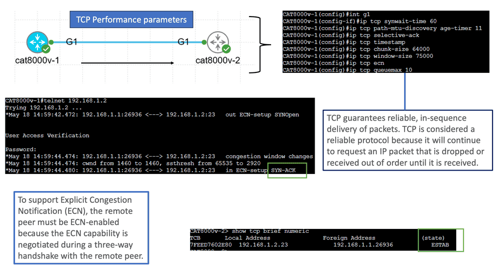
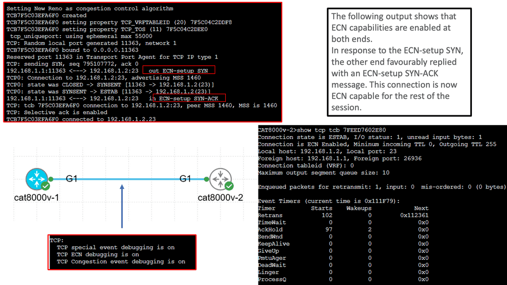
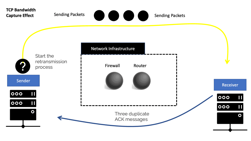
“The discrepancy and uneven bandwidth allocation for flow boil down to the natural behavior of how TCP reacts and interacts with insufficient packet buffers and the resulting packet drops. The behavior is known as the TCP/IP bandwidth capture effect. The TCP/IP bandwidth capture effect does not affect the overall bandwidth but more individual Query Completion Times and Flow Completion Times (FCT) for applications. The QCT and FCT are prime metrics for measuring TCP-based application performance. A TCP stream’s pace of transmission is based on a built-in feedback mechanism. The ACK packets from the receiver adjust the sender’s bandwidth to match the available network bandwidth. With each ACK received, the sender’s TCP starts to incrementally increase the pace of sending packets to use all available bandwidth. On the other hand, it takes 3 duplicate ACK messages for TCP to conclude packet loss on the connection and start the process of retransmission.”

Enterprise Networking K – Mice and Elephant flows – > https://youtu.be/vCB_JH2o1nk

” There are two types of flows in data center environments. We have a large, elephant and smaller mice flow. Elephant flows might only represent a low proportion of the number of flows but consume most of the total data volume. Mice flows are, for example, control and alarm/control messages and usually pretty significant. As a result, they should be given priority over larger elephant flows, but this is sometimes not the case with simple buffer types that don’t distinguish between flow types. Priority can be given by somehow regulating the elephant flows with intelligent switch buffers. Mice flows are often bursty flows where one query is sent to many servers. This results in many small queries getting sent back to the single originating host. These messages are often small only requiring 3 to 5 TCP packets. As a result, the TCP congestion control mechanism may not even be evoked as the congestion mechanisms take 3 duplicate ACK messages. Due to the size of elephant flows they will invoke the TCP congestion control mechanism (mice flows don’t as they are too small).

Enterprise Networking LMultipath TCP – > https://youtu.be/Dfykc40oWzI

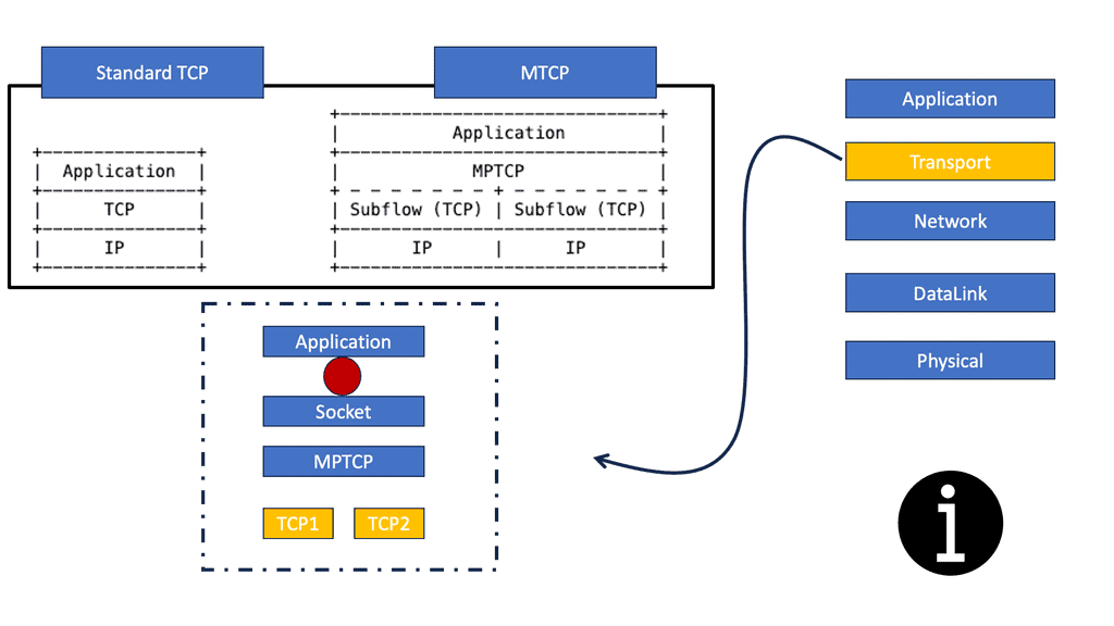
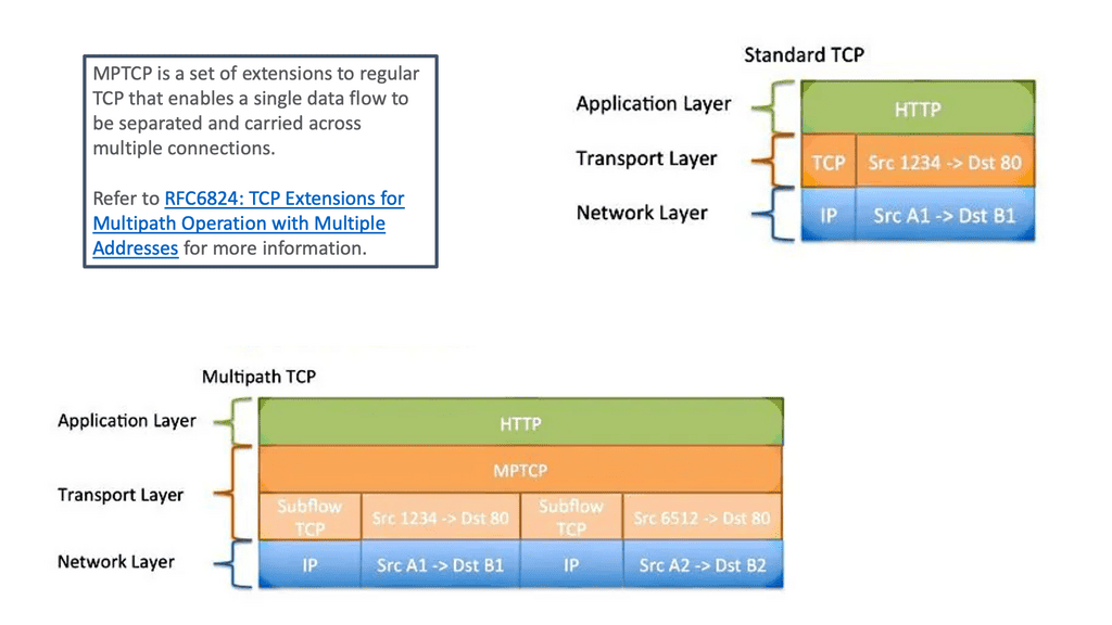
“Transmission Control Protocol (TCP) applications offer reliable byte stream with congestion control mechanisms adjusting flows to current network load. Designed in the 70s, TCP is the most widely used protocol and remains largely unchanged, unlike the networks it operates within. Back in those days the designers understood there could be link failure and decided to decouple the network layer (IP) from the transport layer (TCP). This enables the routing with IP around link failures without breaking the end-to-end TCP connection. Dynamic routing protocols do this automatically without the need for transport layer knowledge. Even Though it has wide adoption, it does not fully align with the multipath characteristics of today’s networks. TCP’s main drawback is that it’s a single path per connection protocol. A single path means once the stream is placed on a path ( endpoints of the connection) it can not be moved to another path even though multiple paths may exist between peers. This characteristic is suboptimal as the majority of today’s networks, and end hosts have multipath characteristics for better performance and robustness.”

Enterprise Networking MMultipath TCP use cases – > https://youtu.be/KkL_yLNhK_E

“Multipath TCP is particularly useful in the multipath data center and mobile phone environments. All mobiles allow you to connect via WiFi and a 3G network. MPTCP enables either the combined throughput and the switching of interfaces ( Wifi / 3G ) without disrupting the end-to-end TCP connection. For example, if you are currently on a 3G network with an active TCP stream, the TCP stream is bound to that interface. If you want to move to the Wifi network you need to reset the connection and all ongoing TCP connections will, therefore, get reset. With MPTCP the swapping of interfaces is transparent. Next-generation leaf and spine data center networks are built with Equal-Cost Multipath (ECMP). Within the data center, any two endpoints are equidistant. For one endpoint to communicate to another, a TCP flow is placed on a single link, not spread over multiple links. As a result, single-path TCP collisions may occur, reducing the throughput available to that flow. This is commonly seen for large flows and not small mice flow.”

Enterprise Networking N – > Multipath TCP connection setup – > https://youtu.be/ALAPKcOouAA

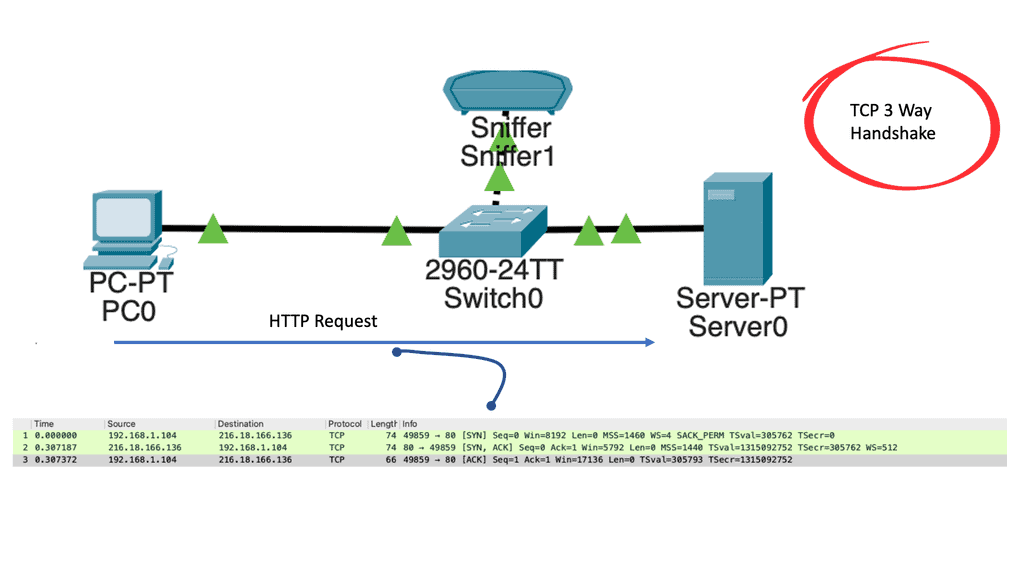
“The aim of the connection is to have a single TCP connection with many subflows. The two endpoints using MPTCP are synchronized and have connection identifiers for each of the subflows. MPTCP starts the same as regular TCP. If additional paths are available additional TCP subflow sessions are combined into the existing TCP session. The original TCP session and other subflow sessions appear as one to the application, and the main Multipath TCP connection seems like a regular TCP connection. The identification of additional paths boils down to the number of IP addresses on the hosts. The TCP handshake starts as normal, but within the first SYN, there is a new MP_CAPABLE option ( value 0x0 ) and a unique connection identifier. This allows the client to indicate they want to do MPTCP. At this stage, the application layer just creates a standard TCP socket with additional variables indicating that it wants to do MPTCP. If the receiving server end is MP_CAPABLE it will reply with the SYN/ACK MP_CAPABLE along with its connection identifier. Once the connection is agreed the client and server will set upstate. Inside the kernel, this creates a Meta socket acting as the layer between the application and all the TCP subflows.”

More Videos to come!

Additional Enterprise Networking information can be found at the following:

multipath tcp

Multipath TCP

Multipath TCP

In today's interconnected world, a seamless and reliable internet connection is paramount. Traditional TCP/IP protocols have served us well, but they face challenges in handling modern network demands. Enter Multipath TCP (MPTCP), a groundbreaking technology that has the potential to revolutionize internet connections. In this blog post, we will explore the intricacies of MPTCP, its benefits, and its implications for the future of networking.

MPTCP, as the name suggests, allows a single data stream to be transmitted across multiple paths simultaneously. Unlike traditional TCP, which relies on a single path, MPTCP splits the data into subflows, distributing them across different routes. This enables the utilization of multiple network interfaces, such as Wi-Fi, cellular, or wired connections, to enhance performance, resilience, and overall user experience.

One of the key advantages of MPTCP lies in its ability to provide robustness and resilience. By utilizing multiple paths, MPTCP ensures that data transmission remains uninterrupted even if one path fails or experiences congestion. This redundancy significantly improves the reliability of connections, making it particularly valuable for critical applications such as real-time streaming and online gaming.

Implementing MPTCP requires both client and server-side support. Fortunately, MPTCP has gained significant traction, and numerous operating systems and network devices have begun incorporating native support for this protocol. From Linux to iOS, MPTCP is gradually becoming a standardized feature, empowering users with enhanced connectivity options.

The versatility of MPTCP opens up a plethora of possibilities for various applications. For instance, in the context of mobile devices, MPTCP can seamlessly switch between Wi-Fi and cellular networks, optimizing connectivity and ensuring uninterrupted service. Additionally, MPTCP holds promise for cloud computing, content delivery networks, and distributed systems, where the concurrent utilization of multiple paths can significantly improve performance and efficiency.

Highlights: Multipath TCP

TCP restricts communication

Multiple paths connect hosts, but TCP restricts communications to a single path per transport connection. Multiple paths could be used concurrently within the network to maximize resource usage. The user experience should be enhanced by improved resilience to network failures and higher throughput.

Due to protocol constraints both on the end systems and within the network, Internet resources (particularly bandwidth) are often not fully utilized as the Internet evolves. The end-user experience could be significantly improved if these resources were used simultaneously.

A similar improvement in user experience could also be achieved without as much expenditure on network infrastructure. In resource pooling, these available resources are ‘pooled’ into one logical resource for the user by applying the technique of resource pooling.

The goal of resource pooling

As part of multipath transport, disjoint (or partially disjoint) paths across a network are simultaneously used to achieve some of the goals of resource pooling. In addition to increasing resilience, multipath transport protects end hosts from failures on one path. As a result, network capacity can be increased by improving resource utilization efficiency. In a multipath TCP connection, multiple paths are pooled transparently within a transport connection to achieve multipath TCP goals.

When one or both hosts are multihomed, multipath TCP uses multiple paths end-to-end. A host can also manipulate the network path by changing port numbers with Equal Cost MultiPath (ECMP), for example, to create multiple paths within the network.

Multipath TCP and TCP

Multipath TCP (MPTCP) is a protocol extension that allows for the simultaneous use of multiple network paths between two endpoints. Traditionally, TCP (Transmission Control Protocol) relies on a single path for data transmission, which can limit performance and reliability. With MPTCP, multiple paths can be established between the sender and receiver, enabling the distribution of traffic across these paths. This offers several advantages, including increased throughput, better load balancing, and improved resilience against network failures.

Automatically Set Up Multiple Paths.

It is designed to automatically set up multiple paths between two endpoints and use those paths to send and receive data efficiently. It also provides a mechanism for detecting and recovering from packet loss and for providing low-latency communication. MPTCP is used in applications that require high throughput and low latency, such as streaming media, virtual private networks (VPNs), and networked gaming. MPTCP is an extension to the standard TCP protocol and is supported by most modern operating systems, including Windows, macOS, iOS, and Linux.

High Throughput & Low Latency

MPTCP is an attractive option for applications that require high throughput and low latency, as it can provide both. Additionally, it can provide fault tolerance and redundancy, allowing an application to remain operational even if one or more of its paths fail. This makes it useful for applications such as streaming media, where high throughput and low latency are essential, and reliability is critical.

Before you proceed, you may find the following helpful:

  1. Software Defined Perimeter
  2. Event Stream Processing
  3. Application Aware Networking


TCP Multipath.

Key Multipath TCP Discussion points:


  • Introduction of multiple paths for a single TCP session.

  • Discussion on TCP Subflow.

  • MP-TCP setup. 

  • Multipath networking use cases

  • The issues with TCP congestion control

Back to Basic: Reliability in Multipath TCP

Reliable byte streams

To start the discussion on multipath TCP, we must understand the basics of Transmission Control Protocol (TCP) and its effect on IP Forwarding. TCP applications offer reliable byte streams with congestion control mechanisms that adjust flows to the current network load. Designed in the 1970s, TCP is the most widely used protocol and remains unchanged, unlike the networks it operates within. In those days, the designers understood there could be link failure and decided to decouple the network layer (IP) from the transport layer (TCP).

This enables the routing with IP around link failures without breaking the end-to-end TCP connection. Dynamic routing protocols such as BGP Multipath do this automatically without the need for transport layer knowledge. Even though it has wide adoption, it does not fully align with the multipath networking requirements of today’s networks, driving the need for MP-TCP.

TCP delivers reliability using distinct variations of the techniques. Because it provides a byte stream interface, TCP must convert a sending application’s stream of bytes into a set of packets that IP can carry. This is called packetization. These packets contain sequence numbers, which in TCP represent the byte offsets of the first byte in each packet in the overall data stream rather than packet numbers. This allows packets to be of variable size during a transfer and may also allow them to be combined, which is called repacketization.

Diagram: The need for MP-TCP.

TCP’s main drawback is that it’s a single path per connection protocol. A single path means once the stream is placed on a path ( endpoints of the connection), it can not be moved to another path even though multiple paths may exist between peers. This characteristic is suboptimal as most of today’s networks and end hosts have multipath characteristics for better performance and robustness.

What is Multipath TCP?

Multipath TCP, also known as MPTCP, is an extension to the traditional TCP protocol that allows a single TCP connection to utilize multiple network paths simultaneously. Unlike conventional TCP, which operates on a single path, MPTCP offers the ability to distribute the traffic across multiple paths, enabling more efficient resource utilization and increased overall network capacity.

Critical Benefits of Multipath TCP:

1. Improved Performance: MPTCP can distribute the data traffic using multiple paths, enabling faster transmission rates and reducing latency. This enhanced performance is particularly beneficial for bandwidth-intensive applications such as streaming, file transfers, and video conferencing, where higher throughput and reduced latency are crucial.

2. Increased Resilience: MPTCP enhances network resilience by providing seamless failover capabilities. In traditional TCP, if a network path fails, the connection is disrupted, resulting in a delay or even a complete loss of service. However, with MPTCP, if one path becomes unavailable, the connection can automatically switch to an alternative path, ensuring uninterrupted communication.

3. Efficient Resource Utilization: MPTCP allows for better utilization of available network resources. Distributing traffic across multiple paths prevents congestion on a single path and optimizes the usage of available bandwidth. This results in more efficient utilization of network resources and improved overall performance.

4. Seamless Transition between Networks: MPTCP is particularly useful in scenarios where devices need to switch between different networks seamlessly. For example, when a mobile device moves from a Wi-Fi network to a cellular network, MPTCP can maintain the connection and seamlessly transfer the ongoing data traffic to the new network without interruption.

5. Compatibility with Existing Infrastructure: MPTCP is designed to be backward compatible with traditional TCP, making it easy to deploy and integrate into existing network infrastructure. It can coexist with legacy TCP connections and gradually adapt to MPTCP capabilities as more devices and networks support the protocol.

Multipath TCP

Main Multipath TCP Components

Multipath TCP

  • Allows a single transmission control protocol (TCP) connection to use multiple network paths simultaneously.

  • Automatically set up multiple paths between two endpoints.

  • TCP’s main drawback is that it’s a single path per connection protocol.

  • MPTCP enhances network resilience by providing seamless failover capabilities.

Multiple Paths for a Single TCP Session

Using multiple paths for a single TCP session increases resource usage and resilience for TCP optimization. All this is achieved with additional extensions added to regular TCP, simultaneously enabling connection transport across multiple links.

The core aim of Multipath TCP (MP-TCP) is to allow a single TCP connection to use multiple paths simultaneously by using abstractions at the transport layer. As it operates at the transport layer, the upper and lower layers are transparent to its operation. No network or link-layer modifications are needed.

There is no need to change the network or the end hosts. The end hosts use the same socket API call, and the network continues to operate as before. No unique configurations are required as it’s a capability exchange between hosts. Multipath TCP enabling multipath networking is 100% backward compatible with regular TCP.

Multipath TCP
Diagram: Multipath TCP. Source is Cisco

TCP sub flows

MPTCP achieves its goals through sub-flows of individual TCP connections forming an MPTCP session. These sub-flows can be established over different network paths, allowing for parallel data transmission. MPTCP also includes mechanisms for congestion control and data sequencing across the sub-flows, ensuring reliable packet delivery.

MP-TCP binds a TCP connection between two hosts, not two interfaces, like regular TCP. Regular TCP connects two IP endpoints by establishing a source/destination by IP address and port number. The application has to choose a single link for the connection. However, MPTCP creates new TCP connections known as sub-flows, allowing the application to take different links for each subflow. 

Subflows are set up the same as regular TCP connections. They consist of a flow of TCP segments operating over individual paths but are still part of the overall MPTCP connection. Subflows are never fixed and may fluctuate in number during the lifetime of the parent Multipath TCP connection.

mp-tcp
Diagram: MP-TCP.

Multipath TCP uses cases.

The deployment of MPTCP has the potential to benefit various applications and use cases. For example, MPTCP can enable seamless handovers between cellular towers or Wi-Fi access points in mobile networks, providing uninterrupted connectivity. MPTCP can improve server-to-server communications in data centers by utilizing multiple links and avoiding congestion.

Multipath TCP is beneficial in multipath data centers and mobile phone environments. All mobiles allow you to connect via wifi and a 3G network. MP-TCP enables the combined throughput and the switching of interfaces (wifi / 3G ) without disrupting the end-to-end TCP connection.

For example, if you are currently on a 3G network with an active TCP stream, the TCP stream is bound to that interface. If you want to move to the wifi network, you need to reset the connection, and all ongoing TCP connections will reset. With MP-TCP, the swapping of interfaces is transparent.

Multipath networking: leaf-spine data center

Leaf and spine data centers are a revolutionary networking architecture that has revolutionized connectivity in modern data centers. Unlike traditional hierarchical designs, leaf and spine networks are based on a non-blocking, fully meshed structure. The leaf switches act as access points, connecting directly to the spine switches, creating a flat network topology.

Key Characteristics of Leaf and Spine Data Centers

One of the key characteristics of leaf and spine data centers is their scalability. With the non-blocking architecture, leaf and spine networks can easily accommodate the increasing demands of modern data centers without sacrificing performance. Additionally, they offer low latency, high bandwidth, and improved resiliency compared to traditional designs.

Next-generation leaf and spine data center networks are built with Equal-Cost Multipath (ECMP). Within the data center, any two endpoints are equidistant. For one endpoint to communicate with another, a TCP flow is placed on a single link, not spread over multiple links. As a result, single-path TCP collisions may occur, reducing the throughput available to that flow.

what is spine and leaf architecture
Diagram: What is spine and leaf architecture? 2-Tier Spine Leaf Design

This is commonly seen for large flows and not small mice flow. When a server starts a TCP connection in a data center, it gets placed on a path and stays there. With MP-TCP, you could use many sub-flows per connection instead of a single path per connection. Then, if some of those sub-flows get congested, you don’t send over that subflow, improving traffic fairness and bandwidth optimizations.

Hash-based distribution

The default behavior of spreading traffic through a LAG or ECMP next hops is based on the hash-based distribution of packets. First, an array of buckets is created, and each outbound link is assigned to one or more buckets. Next, fields such as source-destination IP address / MAC address are taken from the outgoing packet header and hashed based on this endpoint identification. Finally, the hash selects a bucket, and the packet is queued to the interface assigned to that bucket. 

redundant links
Diagram: Redundant links with EtherChannel. Source is jmcritobal

The issue is that the load-balancing algorithm does not consider interface congestions or packet drops. With all mice flows, this is fine, but once you mix mice and elephant flows together, your performance will suffer. An algorithm is needed to identify congested links and then reshuffle the traffic.

A good use for MPTCP is a mix of mice and elephant flows. Generally, MP-TCP does not improve performance for environments with only mice flows.

Small files, say 50 KB, offer the same performance as regular TCP. Multipath networking usually has the same results as link bonding as the file size increases. The benefits of MP-TCP come into play when files are enormous (300 KB ). MP-TCP outperforms link bonding at this level as the congestion control can better balance the load over the links.

MP-TCP connection setup

The connection aims to have a single TCP connection with many sub-flows. The two endpoints using MPTCP are synchronized and have connection identifiers for each sub-flow. MPTCP starts the same as regular TCP. Additional TCP subflow sessions are combined into the existing TCP session if different paths are available. The original TCP and other subflow sessions appear as one to the application, and the primary Multipath TCP connection seems like a regular TCP connection. Identifying additional paths boils down to the number of IP addresses on the hosts. 

tcp multipath
Diagram: TCP Multipath.

The TCP handshake starts as expected, but within the first SYN, there is a new MP_CAPABLE option ( value 0x0 ) and a unique connection identifier. This allows the client to indicate that they want to do MPTCP. At this stage, the application layer creates a standard TCP socket with additional variables telling it intends to do MPTCP.

If the receiving server end is MP_CAPABLE, it will reply with the SYN/ACK MP_CAPABLE and its connection identifier. Once the connection is agreed upon, the client and server will set up the upstate. Inside the kernel, a Meta socket is the layer between the application and all the TCP sub-flows.

Under a multipath condition and when multiple paths are detected (based on IP addresses), the client starts a regular TCP handshake with the MP_JOIN option (value 0x1) and uses the connection identifier for the server. The server then replies with a subflow setup. New sub-flows are created, and the scheduler will schedule over each sub-flow as the data is sent from the application to the meta socket. 

TCP sequence numbers 

Regular TCP uses sequence numbers, enabling the receiving side to return packets in the correct order before sending them to the application. The sender can determine which packets are lost by looking at the ACK.

For MP-TCP, packets must travel multiple paths, so sequence numbers are needed to restore packet order before they are passed to the application. The sequence numbers also inform the sender of any packet loss on a path. When an application sends a packet, the segment is assigned a data sequence number.

TCP looks at the sub-flows to see where to send this segment. When it ships on a subflow, it uses a sequence number and puts it in the TCP header, and the other data sequence number gets set in the TCP options. 

The sequence number on the TCP header informs the client of any packet loss. The recipient also uses the data sequence number to reorder packets before sending them to the application.

Congestion control

Congestion control was never a problem in circuit switching. Resources are reserved at call setup to prevent congestion during data transfer, resulting in a lot of bandwidth underutilization due to the reservation of circuits. We then moved to packet switching, where we had a single link with no reservation, but the flows could use as much of the link as they wanted. This increases the utilization of the link and also the possibility of congestion.

To help this situation, congestion control mechanisms were added to TCP. Similar TCP congestion control mechanisms are employed for MP-TCP. Standard TCP congestion control maintains a congestion window for each connection, and you increase the window size on each ACK. With a drop, you half the window. 

MP-TCP operates similarly. You maintain one congestion window for each subflow path. Similar to standard TCP, when you have a drop on a subflow, you have half the window for that subflow. However, the increased rules are different from expected TCP behavior.

It gives more of an increase for sub-flows with a larger window. A larger window means it has a lower loss. As a result, traffic moves from congested to uncongested links dynamically.

Summary: Multipath TCP

The networking world is constantly evolving, with new technologies and protocols being developed to meet the growing demands of our interconnected world. One such protocol that has gained significant attention recently is Multipath TCP (MPTCP). In this blog post, we dived into the fascinating world of MPTCP, its benefits, and its potential applications.

Section 1: Understanding Multipath TCP

Multipath TCP, often called MPTCP, is an extension of the traditional TCP protocol that allows for simultaneous data transmission across multiple paths. Unlike conventional TCP, which operates on a single path, MPTCP leverages multiple network interfaces, such as Wi-Fi and cellular connections, to improve overall network performance and reliability.

Section 2: Benefits of Multipath TCP

By utilizing multiple paths, MPTCP offers several key advantages. Firstly, it enhances throughput by aggregating the bandwidth of multiple network interfaces, resulting in faster data transfer speeds. Additionally, MPTCP improves resilience by providing seamless failover between different paths, ensuring uninterrupted connectivity even if one path becomes congested or unavailable.

Section 3: Applications of Multipath TCP

The versatility of MPTCP opens the door to a wide range of applications. One notable application is in mobile devices, where MPTCP can intelligently combine Wi-Fi and cellular connections to provide users with a more stable and faster internet experience. MPTCP also finds utility in data centers, enabling efficient load balancing and reducing network congestion by distributing traffic across multiple paths.

Section 4: Challenges and Future Developments

While MPTCP brings many benefits, it also presents challenges. One such challenge is ensuring compatibility with existing infrastructure and devices that may not support MPTCP. Additionally, optimizing MPTCP’s congestion control mechanisms and addressing security concerns are ongoing research and development areas.

Conclusion:

Multipath TCP is a groundbreaking protocol that has the potential to revolutionize the way we experience network connectivity. With its ability to enhance throughput, improve resilience, and enable new applications, MPTCP holds great promise for the future of networking. As researchers continue to address challenges and refine the protocol, we can expect even greater advancements in this exciting field.

Packet loss as a binary code 3D illustration

Dropped Packet Test

Dropped Packet Test

In the world of networking, maintaining optimal performance is crucial. One of the key challenges that network administrators face is identifying and addressing packet loss issues. Dropped packets can lead to significant disruptions, sluggish connectivity, and even compromised data integrity. To shed light on this matter, we delve into the dropped packet test—a powerful tool for diagnosing and improving network performance.

Packet loss occurs when data packets traveling across a network fail to reach their destination. This can happen due to various reasons, including network congestion, faulty hardware, or software glitches. Regardless of the cause, packet loss can have detrimental effects on network reliability and user experience.

The dropped packet test is a method used to measure the rate of packet loss in a network. It involves sending a series of test packets from a source to a destination and monitoring the percentage of packets that fail to reach their intended endpoint. This test provides valuable insights into the health of a network and helps identify areas that require attention.

To perform a dropped packet test, network administrators can utilize specialized network diagnostic tools or command-line utilities. These tools allow them to generate test packets and analyze the results. By configuring parameters such as packet size, frequency, and destination, administrators can simulate real-world network conditions and assess the impact on packet loss.

Once the dropped packet test is complete, administrators need to interpret the results accurately. A high packet loss percentage indicates potential issues that require investigation. It is crucial to analyze the test data in conjunction with other network performance metrics to pinpoint the root cause of packet loss and devise effective solutions.

To address packet loss, network administrators can employ a range of strategies. These may include optimizing network infrastructure, upgrading hardware components, fine-tuning routing configurations, or implementing traffic prioritization techniques. The insights gained from the dropped packet test serve as a foundation for implementing targeted solutions and improving overall network performance.

Highlights: Dropped Packet Test

Testing For Packet Loss

How to test for packet loss on a network? The following post provides information on testing packet loss and network packet loss test. Today’s data center performance has to factor in various applications and workloads with different consistency requirements.

Understanding what is best per application/workload requires a dropped packet test from different network parts. Some applications require predictable latency, while others sustain throughput. It’s usually the case that the slowest flow is the ultimate determining factor affecting the end-to-end performance.

Consistent Bandwidth

We must focus on consistent bandwidth and unified latency for ALL flow types and workloads to satisfy varied conditions and achieve predictable application performance for a low latency network design. Poor performance is due to many factors that can be controlled. 

Start With A Baseline

So, at the start, you must find the baseline and work from there. Baseline engineering is a critical approach to determining the definitive performance of software and hardware. Once you have a baseline, you can work from there, testing packet loss.

Depending on your environment, such tests may include chaos engineering kubernetes, which intentionally brake systems in a controlled environment to learn and optimize performance. To fully understand a system or service, you must deliberately break it. An example of some Chaos engineering tests include:

Chaos Engineering

Example – Chaos Engineering:

  • Simulating the failure of a micro-component and dependency.
  • Simulating a high CPU load and sudden increase in traffic.
  • Simulating failure of the entire AZ ( Availability Zone ) or region.
  • Injecting latency and byzantine failures in services.

Related: Before you proceed, you may find the following helpful:

  1. Multipath TCP
  2. BGP FlowSpec
  3. SASE Visibility
  4. TCP Optimization Mobile Networks
  5. Cisco Umbrella CASB
  6. IPv6 Attacks

Back to Basics: Dropped Packet Test

Reasons for packet loss

Packet loss can occur for several reasons and describes lost packets of data not reaching their destination after being transmitted across a network. Packet loss occurs when network congestion, hardware issues, software bugs, and other factors cause dropped packets during data transmission.

The best way to measure packet loss using ping is to send a series of pings to the destination and look for failed responses. For instance, if you ping something 50 times and get only 49 ICMP replies, you can estimate packet loss at roughly 2%. There is no specific value of what would be a concern. It depends on the application. For example, voice applications are susceptible to latency and loss, but other web-based applications have a lot of tolerance.

However, if I were going to put my finger in the air with some packet loss guidelines, generally, a packet loss rate of 1 to 2.5 percent is acceptable. This is because packet loss rates are typically higher with WiFi networks than with wired systems.

OSI Model and testing

The role of QoS

At this stage, you can look at Quality of Service (QoS), which has different types of application segmentation into other queues. A recommendation would be to put voice traffic into a priority queue. Keep in mind many web browsers cache. This will alleviate some of the performance problems on the Internet for static content that can be cached.

QoS classification

1st Lab Guide: RSVP

RSVP, which stands for Resource Reservation Protocol, is a QoS mechanism that enables network devices to reserve and allocate network resources for specific applications or services. It provides a way to prioritize traffic and ensure critical data flows smoothly through the network, minimizing delays and congestion.

  1. First, we need to enable RSVP on all interfaces: ip rsvp bandwidth 128 64
  2. Then, configure R1 to act like an RSVP host so it will send an RSVP send path message:
  3. Finally. Configure R4 to respond to this reservation:
Resource Reservation
Diagram: Resource Reservation

Key Features and Benefits:

1. Traffic Prioritization: RSVP QoS allows for the classification and prioritization of network traffic based on predefined rules. This ensures that time-sensitive applications, such as real-time video conferencing or Voice over IP (VoIP) calls, receive the necessary bandwidth and minimal latency, resulting in a smoother user experience.

2. Bandwidth Reservation: By reserving a certain amount of network bandwidth for specific applications or services, RSVP QoS prevents network congestion and ensures that critical data packets have a guaranteed path through the network. This is particularly important in scenarios where large file transfers or data-intensive applications are involved.

3. Quality of Experience (QoE) Improvement: RSVP QoS helps improve the overall quality of user experience by reducing packet loss, jitter, and latency. It prioritizes time-sensitive traffic and ensures a reliable network connection, enabling seamless audio and video streaming, fast file downloads, and responsive online gaming.

Significance of Dropped Packet Test:

1. Identifying Network Issues: By intentionally dropping packets, network administrators can identify potential bottlenecks, congestion, or misconfigurations in the network infrastructure. This test helps pinpoint the specific areas where packet loss occurs, enabling targeted troubleshooting and optimization.

2. Evaluating Network Performance: The Dropped Packet Test provides valuable insights into the network’s performance by measuring the packet loss rate. Network administrators can use this information to analyze the impact of packet loss on application performance, user experience, and overall network efficiency.

3. Testing Network Resilience: By intentionally creating packet loss scenarios, network administrators can assess the resilience of their network infrastructure. This test helps determine if the network can handle packet loss without significant degradation and whether backup mechanisms, such as redundant links or failover systems, function as intended.

Implementing the Dropped Packet Test:

Network administrators utilize specialized tools or software to conduct the Dropped Packet Test. These tools generate artificial packet loss by dropping a certain percentage of packets during data transmission. The test can be performed on specific network segments, individual devices, or the entire network infrastructure.

Best Practices for Dropped Packet Testing:

1. Define Test Parameters: Before conducting the test, it is crucial to define the desired packet loss rate, test duration, and the specific network segments or devices to be tested. Having clear objectives ensures that the test yields accurate and actionable results.

2. Conduct Regular Testing: Regularly performing the Dropped Packet Test allows network administrators to proactively detect and resolve network issues before they impact critical operations. It also helps in monitoring the effectiveness of implemented solutions over time.

3. Analyze Test Results: After completing the test, careful analysis of the test results is essential. Network administrators should examine the impact of packet loss on latency, throughput, and overall network performance. This analysis will guide them in making informed decisions to optimize the network infrastructure.

General performance and packet loss testing

The following screenshot is taken from a Cisco ISR router. Several IOS commands can be used to check essential performance. The command shows interface gi1 stats and generic packet in and out information. I would also monitor input and output errors with the command: show interface gi1. Finally, for additional packet loss testing, you can opt for an extended ping that gives you more options than a standard ping. It would be helpful to test from different source interfaces or vary the datagram size to determine any MTU issues causing packet loss.

packet loss testing
Diagram: Packet loss testing.

What Is Packet Loss? Testing Packet Loss

Packet loss results from a packet being sent and somehow lost before it reaches its intended destination. This can happen because of several reasons. Sometimes, a router, switch, or firewall has more traffic coming at it than it can handle and becomes overloaded.

This is known as congestion, and one way to deal with such congestion is to drop packets so you can focus capacity on the rest of the traffic. Here is a quick tip before we get into the details – Keep an eye on buffers!

So, to start testing packet loss, one factor that can be monitored is buffer sizes in the network devices that interconnect source and destination points. Poor buffers cause bandwidth to be unfairly allocated among different types of flows. If some flows do not receive adequate bandwidth, they will exhibit long tails and completion times, degrading performance and resulting in packet drops in the network.

Dropped Packet Test
Diagram: Dropped Packet Test and Packet Loss.

Dropped Packet Test: Application Performance

Network Packet Loss Test

The speed of a network is all about how fast you can move and complete a data file from one location to another. Some factors are easy to influence, and others are impossible, such as the physical distance from one point to the next.

This is why we see a lot of content distributed closer to the source, with intelligent caching, for example, improving user response latency and reducing the cost of data transmission. The TCP’s connection-oriented procedure will affect application performance for different distance endpoints than for source-destination pairs internal to the data center.

We can’t change the laws of physics, and distance will always be a factor, but there are ways to optimize networking devices to improve application performance. One way is to optimize the buffer sizes and select the exemplary architecture to support applications that send burst traffic. There is considerable debate about whether big or small buffers are best or whether we need lossless transport or drop packets.

TCP congestion control

The TCP congestion control and network device buffer significantly affect the time it takes for the flow to complete. TCP was invented over 35 years ago and ensures that sent data blocks are received intact. It creates a logical connection between source-destination pairs and endpoints at the lower IP layer.

The congestion control element was added later to ensure that data transfers can be accelerated or slowed down based on current network conditions. Congestion control is a mechanism that prevents congestion from occurring or relieves it once it appears. For example, the TCP congestion window limits how much data a sender can send into a network before receiving an acknowledgment.

In the following lab guide, I have a host and a web server with a packet sniffer attached. All ports are in the default VLAN, and the server runs the HTTP service. Once we open up the web browser on the host to access the server, we can see the operations of TCP with the 3-way handshake. We have captured the traffic between the client PC and a web server.

TCP uses a three-way handshake process to connect the client and server. (SYN, SYN-ACK, ACK) First things first: Why is a three-way handshake called a three-way handshake? The reason is that three segments are exchanged between the client and server to establish a TCP connection.

Big buffers vs. small buffers

Both small and large buffer sizes have different effects on application flow types. Some sources claim that small buffer sizes optimize performance, while others claim that larger buffers are better.

Many web giants, including Facebook, Amazon, and Microsoft, use small buffer switches. It depends on your environment. Understanding your application traffic pattern and testing optimization techniques are essential to finding the sweet spot. Most out-of-the-box applications will not be fine-tuned for your environment; the only rule of thumb is to lab test.  

TCP interaction

Complications arise when the congestion control behavior of TCP interacts with the network device buffer. The two have different purposes. TCP congestion control continuously monitors network bandwidth using packet drops as the metric. On the other hand, buffering is used to avoid packet loss.

In a congestion scenario, the TCP is buffered, but the sender and receiver cannot know there is congestion, and the TCP congestion behavior is never initiated. So, the two mechanisms used to improve application performance don’t complement each other and require careful packet loss testing for your environment.

Dropped Packet Test: The Approach

Dropped packet test tools.

Ping and Traceroute: Where is the packet loss?

At a fundamental level, we have ping and traceroute. Ping measures round-trip times between your computer and an internet destination. Traceroute measures the routers’ response times along the path between your computer and an internet destination.

These will tell you where the packet loss is occurring and how severe. The next step with the dropped packet test is to find your network’s threshold where packets get dropped. Here, we have more advanced tools to understand protocol behavior, which we will discuss now.

IPEF3, TCP dump, TCP probe: Understanding protocol behavior. 

Tools such as iperf3, TCP dump, and TCP probe can be used to test and understand the effects of TCP. There is no point looking at a vendor’s reports and concluding that their “real-world” testing characteristics fit your environment. They are only guides, and “real-world” traffic tests are misleading. Usually, no standard RFC is used for vendor testing, and they will always try to make their products appear better by tailoring the test ( packet size, etc.) to suit their environment.

As an engineer, you must understand the scenarios you anticipate. Be careful of what you read. Recently, there were conflicting buffer testing results from Arista 7124S and Cisco Nexus 5000.

The Nexus 5000 works best when most ports are congested simultaneously, while the Arista 7100 performs best when some ports are congested but not all. These platforms have different buffer architectures regarding buffer sizes, buffer disciplines, and buffer management, which influence how you test.

TCP congestion control: Bandwidth capture effect

The discrepancy and uneven bandwidth allocation for flow boil down to the natural behavior of how TCP reacts and interacts with insufficient packet buffers and the resulting packet drops. The behavior is known as the TCP/IP bandwidth capture effect.

The TCP/IP bandwidth capture effect does not affect the overall bandwidth but more individual Query Completion Times and Flow Completion Times (FCT) for applications. Therefore, the QCT and FCT are prime metrics for measuring TCP-based application performance.

packet drop test
Diagram: Packet Drop Test and TCP.

A TCP stream’s transmission pace is based on a built-in feedback mechanism. The ACK packets from the receiver adjust the sender’s bandwidth to match the available network bandwidth. With each ACK received, the sender’s TCP increases the pace of sending packets to use all available bandwidth. On the other hand, TCP takes three duplicate ACK messages to conclude packet loss on the connection and start the retransmission process.

TCP-dropped flows

So, in the case of inadequate buffers, packets are dropped to signal the sender to ease the transmission rate. TCP-dropped flows start to back off and naturally receive less bandwidth than the other flows that do not back off.

The flows that don’t back off get hungry and take more bandwidth. This causes some flows to get more bandwidth than others unfairly. By default, the decision to drop some flows and leave others alone is not controlled and is made purely by chance.

This conceptually resembles the Ethernet CSMA/CD bandwidth capture effect in shared Ethernet. Stations colliding with other stations on a shared LAN would back off and receive less bandwidth. This is not too much of a problem because all switches support full-duplex.

DCTP & Explicit Congestion Notification (ECN)

There is a new variant of TCP called DCTP, which improves congestion behavior. When used with commodity, shallow-buffered switches, DCTCP uses 90% less buffer space within the network infrastructure than TCP. Unlike TCP, the protocol is also burst-tolerant and provides low short-flow latency. DCTCP relies on ECN to enhance the TCP congestion control algorithms.

DCTP tries to measure how often you experience congestion and use that to determine how fast it should reduce or increase its offered load based on the congestion level. DCTP certainly reduces latency and provides more appropriate behavior between streams. The recommended approach is to use DCTP with both ECN and Priority Flow control (pause environments).

Dropped packet test with Microbursts

Microbursts are a type of small bursty traffic pattern lasting only for a few microseconds, commonly seen in Web 2 environments. This traffic is the opposite of what we see with storage traffic, which always has large bursts.

Bursts only become a problem and cause packet loss when there is oversubscription; many communicate with one. This results in what is known as fan-in, which causes packet loss. Fan-in could be a communication pattern consisting of 23-to-1 or 47-to-1, n-to-many unicast, or multicast. All these sources send packets to one destination, causing congestion and packet drops. One way to overcome this is to have sufficient buffering.

Network devices need sufficient packet memory bandwidth to handle these types of bursts. Fan-in can increase end-to-end latency-critical application performance if they don’t have the required buffers. Of course, latency is never good for application performance, but it’s still not as bad as packet loss. When the switch can buffer traffic correctly, packet loss is eliminated, and the TCP window can scale to its maximum size.

Mice & elephant flows.

For the dropped packet test, you must consider two flow types in data center environments. First, we have a large elephant and smaller mice flow. Elephant flows might only represent a low proportion of the total number of flows but consume most of the total data volume.

Mice Flows

Elephant Flow

  • Latency-sensitive “mice” flows

  • Consisting of only several packets

  • Alarm/control messages

  •  Throughput-sensitive “elephant” flows

  • Low number of flows BUT

  • Consume most of the data volume

Mice flow, for example, control and alarm/control messages, are usually pretty significant. As a result, they should be given priority over more significant elephant flows, but this is sometimes not the case with simple buffer types that don’t distinguish between flow types.

Properly regulating the elephant flows with intelligent switch buffers can be given priority. Mice flow is often bursty flow where one query is sent to many servers.

Many small queries are sent back to the single originating host. These messages are often small, only requiring 3 to 5 TCP packets. As a result, the TCP congestion control mechanism may not even be evoked as the congestion mechanisms take three duplicate ACK messages. However, due to the size of elephant flows, they will invoke the TCP congestion control mechanism (mice flows don’t as they are too small).

Testing packet loss: Reactions to buffer sizes

When combined in a shared buffer, mice and elephant flows react differently. Small, deep buffers operate on a first-come, first-served basis and do not distinguish between different flow sizes; everyone is treated equally. Elephants can fill out the buffers and starve mice’s flow, adding to their latency.

On the other hand, bandwidth-aggressive elephant flows can quickly fill up the buffer and impact sensitive mice flows. Longer latency results in longer flow completion time, a prime measuring metric for application performance.

On the other hand, intelligent buffers understand the types of flows and schedule accordingly. With intelligent buffers, elephant flows are given early congestion notification, and the mice flow is expedited under stress. This offers a better living arrangement for both mice and elephant flows.

First, you need to be able to measure your application performance and understand your scenarios. Small buffer switches are used for the most critical applications and do very well. You are unlikely to make a wrong decision with small buffers, so it’s better to start by tuning your application. Out-of-the-box behavior is generic and doesn’t consider failures or packet drops.

The way forward is understanding the application and tuning of host and network devices in an optimized leaf and spine fabric. If you have a lot of incest traffic, having large buffers on the leaf will benefit you more than having large buffers on the Spine.


Key Dropped Packet Test Summary Points:

Main Checklist Points To Consider

  • How dropped packets affect data center performance and how you approach this.

  • Technical details on packet loss and what it represents.

  • Technical details on the speed of a network and the effects of TCP control on this. The bandwidth capture effect.

  • Discussion on small vs. large buffers with Arista and Cisco use case.

  • A final note on microbursts and how they may effect network performance.

Closing comments on testing for packet loss

Packet loss is a common issue that can significantly impact network performance and user experience. It refers to losing data packets during transmission from one device to another. This document will guide you through testing packet loss and provide insights into its potential causes and solutions.

I. Understanding Packet Loss:

1. Definition:

Packet loss occurs when data packets sent over a network fail to reach their destination. This can result in data corruption, latency, and decreased overall network performance.

2. Causes of Packet Loss:

a. Network Congestion: High network traffic can overload routers and switches, leading to dropped packets.

b. Faulty Hardware: Damaged cables, faulty network cards, or malfunctioning routers can contribute to packet loss.

c. Software Issues: Inadequate buffer sizes, misconfigured firewalls, or incompatible protocols can cause packet loss.

d. Wireless Interference: Environmental factors such as physical obstacles, electromagnetic interference, or distance from the access point can result in packet loss in wireless networks.

II. Testing Packet Loss:

1. Ping Test:

The ping command is a simple yet effective way to test packet loss. Open the command prompt (Windows) or terminal (Mac/Linux) and type “ping [IP address or domain name].” This will send a series of packets to the specified destination and provide statistics on packet loss.

2. Traceroute:

Traceroute allows you to identify the exact network node where packet loss occurs. Open the command prompt or terminal and type “traceroute [IP address or domain name].” This will display the packets’ path and highlight nodes experiencing packet loss.

3. Network Monitoring Tools:

Various network monitoring tools offer comprehensive packet loss testing. Wireshark, for example, captures network traffic and provides detailed analysis, including packet loss statistics.

III. Troubleshooting Packet Loss:

1. Check Network Hardware:

Inspect network cables, switches, and routers for any signs of damage or malfunction. Replace faulty components if necessary.

2. Update Firmware and Drivers:

Ensure that all network devices have the latest firmware and drivers installed. Manufacturers often release updates to address known issues, including packet loss.

3. Adjust Quality of Service (QoS) Settings:

Configuring QoS settings can help prioritize critical network traffic and mitigate packet loss during periods of high network congestion.

4. Optimize Wireless Network:

Repositioning access points, reducing physical obstacles, or changing wireless channels can minimize wireless interference and significantly reduce packet loss in wireless networks.

The Dropped Packet Test is a valuable diagnostic tool that enables network administrators to identify network issues, evaluate network performance, and assess network resilience. Network administrators can proactively address potential bottlenecks and ensure a reliable and efficient network infrastructure by intentionally creating packet loss scenarios. Regularly conducting the Dropped Packet Test, analyzing the results, and implementing necessary optimizations will help organizations maintain a robust network connection and provide seamless data transmission.

Summary: Dropped Packet Test

Ensuring smooth and uninterrupted data transmission in the fast-paced networking world is vital. One of the challenges that network administrators often encounter is dealing with dropped packets. These packets, which fail to reach their intended destination, can cause latency, data loss, and overall network performance issues. This blog post delved into the dropped packet test, its importance, and how it can help identify and resolve network problems effectively.

Section 1: Understanding Dropped Packets

Dropped packets are packets of data that are discarded or lost during transmission. This can occur for various reasons, such as network congestion, hardware failures, misconfigurations, or insufficient bandwidth. When packets are dropped, it disrupts the data flow and can lead to delays or complete data loss. Understanding the impact of dropped packets is crucial for maintaining a reliable and efficient network.

Section 2: Conducting the Dropped Packet Test

The dropped packet test is a diagnostic technique used to assess the quality and performance of a network. It involves sending test packets through the network and monitoring their successful delivery. By analyzing the results, network administrators can identify potential bottlenecks, misconfigurations, or faulty equipment that may be causing packet loss. This test can be performed using various tools and utilities available in the market, such as network analyzers or packet sniffers.

Section 3: Interpreting Test Results

Once the dropped packet test is conducted, the next step is to interpret the test results. The results will typically provide information about the percentage of dropped packets, the specific network segments or devices where the drops occur, and the potential causes behind the packet loss. This valuable data allows administrators to promptly pinpoint and address the root causes of network performance issues.

Section 4: Troubleshooting and Resolving Packet Loss

Network administrators can delve into troubleshooting and resolving the issue upon identifying the sources of packet loss. This may involve adjusting network configurations, upgrading hardware components, optimizing bandwidth allocation, or implementing Quality of Service (QoS) mechanisms. The specific actions will depend on the nature of the problem and the network infrastructure in place. Administrators can significantly improve network performance and maintain smooth data transmission with a systematic approach based on the dropped packet test results.

Conclusion:

The dropped packet test is an indispensable tool in the arsenal of network administrators. Administrators can proactively address network issues and optimize performance by understanding the concept of dropped packets, conducting the test, and effectively interpreting the results. Organizations can ensure seamless communication, efficient data transfer, and enhanced productivity with a robust and reliable network.