### What is EVPN?
Ethernet VPN (EVPN) is a technology designed to enhance and streamline network virtualization. As businesses increasingly rely on cloud computing and virtualized environments, EVPN provides a scalable and flexible solution for interconnecting data centers and managing complex network architectures. Think of EVPN as a sophisticated method of creating a virtual bridge that connects different network segments, allowing data to flow seamlessly and securely across them.
### How EVPN Works
EVPN operates by using a combination of BGP (Border Gateway Protocol) and MPLS (Multiprotocol Label Switching) to manage and direct traffic flow across virtual networks. This allows for efficient routing and switching, reducing latency and improving overall network performance. By utilizing a centralized control plane, EVPN simplifies network management, making it easier for IT professionals to monitor and adjust network resources as needed.
Discussing EVPN
– Before we delve into the technical intricacies, let’s get a grasp of the fundamentals of EVPN. EVPN is a technology that combines the best of both Layer 2 and Layer 3 connectivity. It offers a flexible and versatile approach to network design, enabling seamless communication between different sites and data centers. By leveraging the power of Multiprotocol Label Switching (MPLS) and Border Gateway Protocol (BGP), EVPN ensures efficient traffic forwarding and network virtualization.
Key EVPN Benefits:
– Now that we have a basic understanding, let’s explore the key benefits that EVPN brings to the table. Firstly, EVPN provides enhanced scalability, allowing organizations to expand their networks without compromising performance. It offers efficient load balancing and traffic engineering capabilities, ensuring optimized resource utilization. Secondly, EVPN enables seamless integration with existing infrastructure, making it an ideal choice for businesses looking to upgrade their networks. Lastly, EVPN provides built-in support for multipath forwarding, promoting high availability and resilience.
Key EVPN Use Cases:
– EVPN has found its place in various real-world applications, revolutionizing network connectivity across industries. One such application is in cloud service providers’ data centers, where EVPN enables efficient interconnectivity between virtual machines and facilitates workload mobility. Additionally, EVPN is widely used in enterprise networks, enabling seamless connectivity between different branches and ensuring secure communication across the organization. EVPN also plays a crucial role in service provider networks, offering scalable and flexible solutions for delivering services to customers.
Note: EVPN Considerations
1 Enhanced Scalability: Unlike traditional Layer 2 VPNs, EVPN efficiently utilizes network resources by implementing a single control plane. This eliminates the need for flooding broadcasts across the entire network, resulting in improved scalability and more efficient data transmission.
2 Seamless Multicast Support: EVPN provides native support for multicast traffic, making it an ideal choice for applications that rely on efficient multicast distribution. With EVPN, multicast streams can be seamlessly propagated across the network, ensuring optimal performance and reducing bandwidth consumption.
3 Simplified Network Management: EVPN offers a centralized control plane, allowing for simplified network management and configuration, and with the use of BGP as the control protocol, EVPN leverages existing routing mechanisms, making it easier to integrate with existing networks and reducing the complexity of network operations.
Real-World Applications of EVPN
1 Data Center Interconnectivity: EVPN is widely adopted in data centers, enabling efficient interconnectivity between different sites. By supporting Layer 2 and Layer 3 services simultaneously, EVPN simplifies the deployment and management of multi-site architectures, providing seamless connectivity for virtual machines and containers.
2 Service Provider Edge: EVPN has gained traction due to its versatility and scalability in the service provider space. Service providers can leverage EVPN to deliver flexible and robust connectivity services, such as E-LAN and E-VPN, to their customers. EVPN’s ability to support multiple Layer 2 and Layer 3 services on a single platform makes it an attractive solution for service providers.
Understanding EVPN Fundamentals
EVPN, at its core, is a technology that combines the best of both Layer 2 and Layer 3 networking. Utilizing the BGP (Border Gateway Protocol) enables the creation of virtual private networks over an Ethernet infrastructure. This unique approach brings numerous advantages, such as improved scalability, simplified management, and seamless integration with existing protocols.
BGP For the Data Center
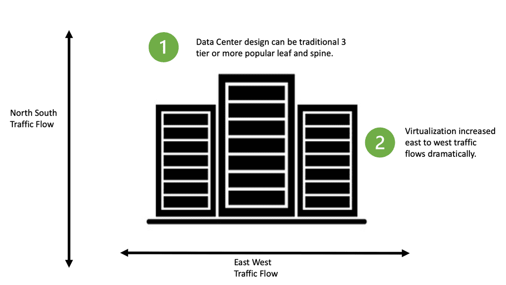
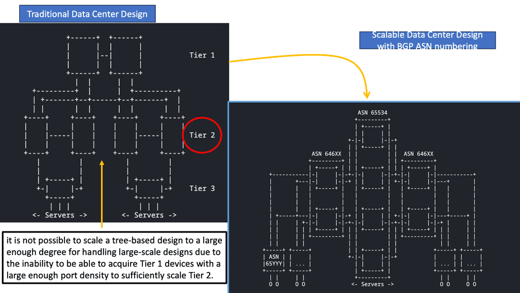
A shift in strategy has led to the evolution of data center topologies from three-tiers to three-stage Clos architectures (and five-stage Clos fabrics for large-scale data centers), eliminating protocols such as Spanning Tree, which made the infrastructure more challenging to operate (and more expensive) to maintain by blocking redundant paths by default.
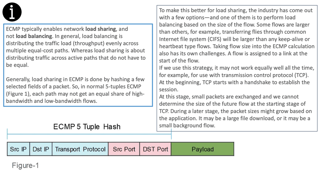
A routing protocol was needed to convert the network natively to Layer 3 with ECMP. The control plane should be simplified, control plane interactions should be minimized, and network downtime should be minimized as much as possible.
Before the introduction of BGP, service provider networks primarily used it to reach autonomous systems. Before recently, BGP was the interdomain routing protocol on the Internet. Unlike interior gateway protocols such as Open Shortest Path First (OSPF) and Intermediate System-to-Intermediate System (IS-IS), which use a shortest path first logic, BGP relies on routing based on policy (with the autonomous system number [ASN] acting as a tiebreaker in most cases).
Key Point: RFC 7938
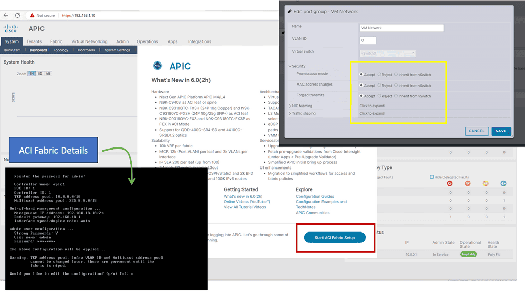
“Use of BGP for Routing in Large-Scale Data Centers,” RFC 7938, explains that BGP with a routed design can benefit data centers with a 3-stage or 5-stage Clos architecture. In VXLAN fabrics, external BGP (eBGP) can be used as an underlay and an overlay. Using eBGP as an underlay, this chapter will show how BGP can be adapted for the data center, offering the following features for large-scale deployments:
Implementation is simplified by relying on TCP for underlying transport and adjacency establishment. Well-known ASN schemes and minimal design changes prevent such problems despite the assumption that BGP will take longer to converge.
Example: In Junos, BGP groups provide a vertical separation between eBGP for the underlay (for IPv4 or IPv6) and eBGP for the overlay (for EVPN addresses). Overlay and underlay BGP simplify maintenance and operations. Besides that, eBGP is generally easier to deploy and troubleshoot than internal BGP (iBGP), which relies on route reflectors (or confederations).
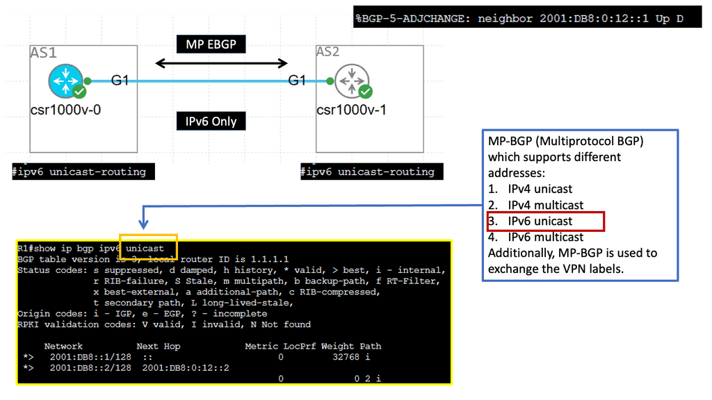
BGP neighbors can be automatically discovered through link-local IPv6 addressing, and NLRI can be transported over IPv6 peering using RFC 8950 (which replaces RFC 5549).
Example BGP Technology: IPv6 and MBGP
VXLAN-based fabrics
VXLAN uses a control plane protocol for remote MAC address learning as a network virtualization overlay. VXLAN-based data center fabrics benefit greatly from BGP Ethernet VPNs (EVPNs) over traditional Layer 2 extension mechanisms like VPLS. Layer 2 and 3 overlays can be built, IP reachability information can be provided, and data-driven learning is no longer required to disseminate MAC addresses due to its inability to scale.
VXLAN-based data center fabrics use several route types, and this chapter explains each type and its packet format.
Extending BGP
What is EVPN? EVPN (Ethernet Virtual Private Network) extends to Border Gateway Protocol (BGP), allowing the network to carry endpoint reachability information such as layer 2 MAC and layer 3 IP addresses. This control plane technology uses MP-BGP for MAC and IP address endpoint distribution. One initial consideration is that layer 2 MAC addresses are treated as IP routes. It is based on standards defined by the IEEE 802.1Q and 802.1ad specifications.
Connects Layer 2 Segments
EVPN, also known as Ethernet VPN, connects L2 network segments separated by an L3 network. This is accomplished by building the L2 VPN network as a virtual Layer 2 network overlay over the Layer 3 network. It uses Border Gateway Protocol (BGP) for routing control as its control protocol. EVPN is a BGP-based control plane that can implement Layer 2 and Layer 3 VPNs.
**Understanding MP-BGP in the Context of EVPN**
MP-BGP is essentially an extension of the traditional BGP, enabling it to carry routing information for multiple network layer protocols. Its application in EVPN is particularly noteworthy. EVPN utilizes MP-BGP to distribute MAC and IP address information, ensuring seamless communication and connectivity across different network segments. This capability is essential for modern data centers, which require high levels of scalability and flexibility.
**Key Advantages of MP-BGP for Endpoint Distribution**
One of the standout benefits of using MP-BGP for MAC and IP endpoint distribution is its scalability. As network demands grow, MP-BGP can handle increased numbers of endpoints without significant degradation in performance. Additionally, its ability to integrate with EVPN allows for dynamic and efficient routing, reducing the complexity often associated with large-scale network operations. This integration results in more stable and reliable network performance, a critical factor for businesses dependent on continuous connectivity.
Related: Before you proceed, you may find the following useful:
Hierarchical networks
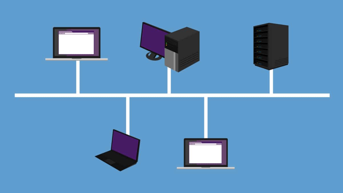
Organizations have built hierarchical networks in the past decades using hierarchical addressing mechanisms such as the Internet Protocol (IP) or creating and interconnecting multiple network domains. Large bridged domains have always presented a challenge for scaling and fault isolation due to Layer 2 and nonhierarchical address spaces. As endpoint mobility has increased, technologies are needed to build more efficient Layer 2 extensions and reintroduce hierarchies.
The Data Center Interconnect (DCI) technology uses dedicated interconnectivity to restore hierarchy within the data center. Even though DCI can interconnect multiple data centers within a single data center, large fabrics enable borderless endpoint placement and mobility. This trend resulted in an explosion of ARP and MAC entries. VXLAN’s Layer 2 over Layer 3 capabilities were supposed to address this challenge. However, they have only added to it, allowing even larger Layer 2 domains to be built as the location boundary is overcome.
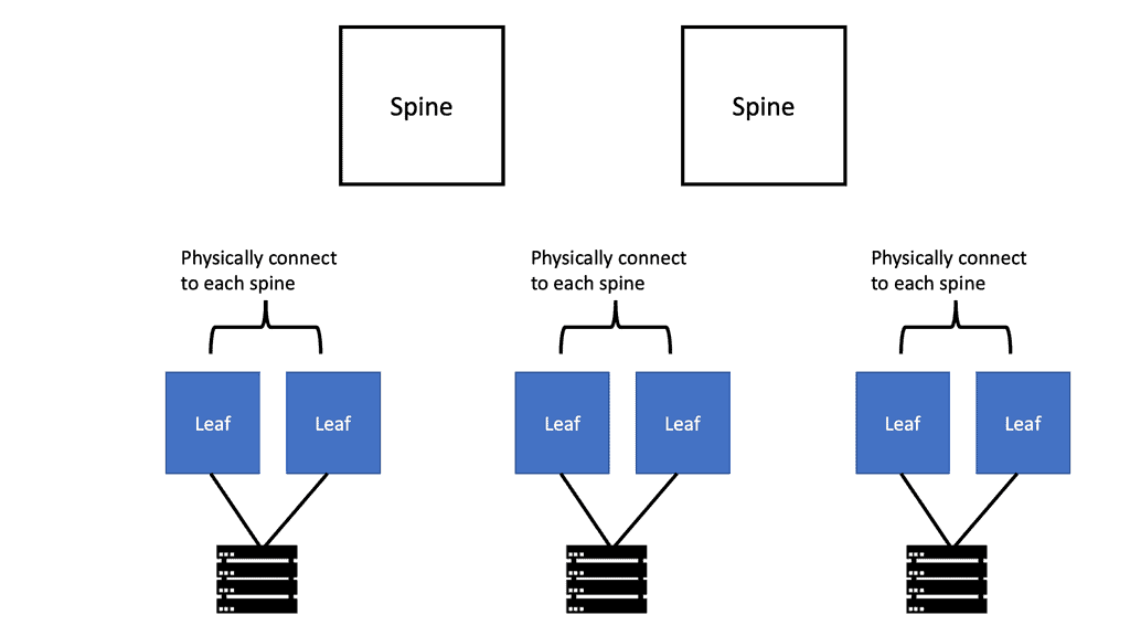
**Spine and Leaf Designs**
The spine and leaf, fat tree, and folded Clos topologies became standard for fabrics. VXLAN, an over-the-top network, flattens out the hierarchy of the new network topology models. With the introduction of the overlay network, the network hierarchy was hidden, even though the underlying topology was predominantly Layer 3, and hierarchies were present. In addition to its benefits, flattening has some drawbacks as well. The simplicity of building a network over the top without touching every switch makes it easy to extend across multiple sites.
As a result, this new overlay networking design presents a risk without failure isolation, especially in large, stretched Layer 2 networks. Whatever is sent through the ingress point to the respective egress point will leave the overlay network. This is done using the “closest to the source” and “closest to the destination” approaches.
With EVPN Multi-Site, overlay networks can maintain hierarchies again. A new version of EVPN Multi-Site for VXLAN BGP EVPN networks introduces external BGP (eBGP), while interior BGP (iBGP) has been the dominant model. The Border Gateways (BGWs) were introduced with autonomous systems (ASs) as a response to eBGP next-hop behavior. Hierarchies are effectively used to classify and connect multiple overlay networks using this approach. Moreover, network extensions within and beyond one data center are controlled and enforced by a control point.
**The Role of Layer 2**
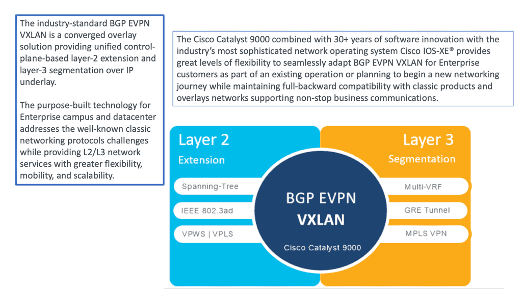
It started as a pure Layer 2 solution and got some Layer 3 functionality pretty early on. Later, it got all the blown IP prefixes, so now you can use EPVN to implement complete Layer 2 and Layer VPNs. EVPN is now considered a mature technology that has been available in multiprotocol label switching (MPLS) networks for some time.
Therefore, many refer to this to it as EVPN over MPLS. When discussing EVPN-MPLS or MPLS EVPN, EPVN still uses Route Distinguisher (RD) and Route Targets (RT).
RD creates separate address spaces, and RT integrates VPN membership. Remember that the precursor to EVPN was Over-the-Top Virtualization (OTV), a proprietary technology invented by Dino Farinacci while working at Cisco. Dino also worked heavily with the LISP protocol.
OTV used Intermediate System–to–Intermediate System (IS-IS) as the control plane and ran over IP networks. IS-IS can build paths for both unicast and multicast routes.
Data center fabric journey
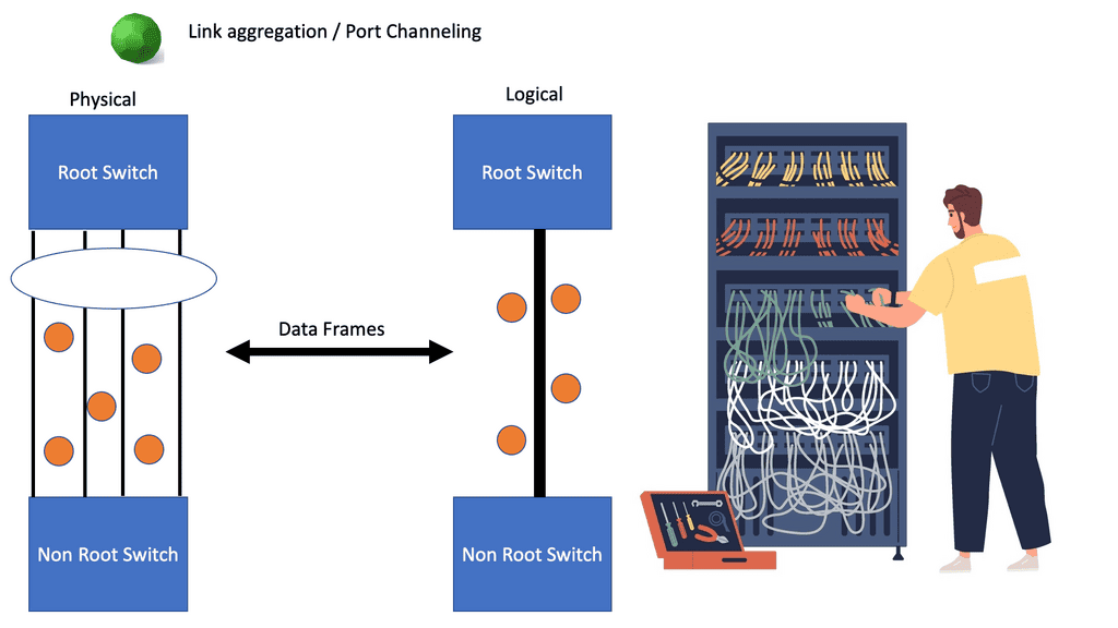
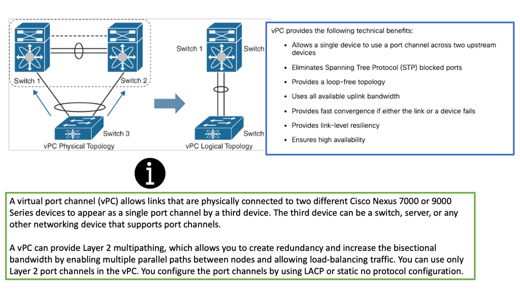
Spanning Tree and Virtual PortChannel
We have evolved data center networks over the past several years. Spanning Tree Protocol (STP)–-based networks served network requirements for several years. Virtual PortChannel (vPC) was introduced to address some of the drawbacks of STP networks while providing dual-homing abilities. Subsequently, overlay technologies such as FabricPath and TRILL came to the forefront, introducing routed Layer 2 networks with a MAC-in-MAC overlay encapsulation. This evolved into a MAC-in-IP overlay with the invention of VXLAN.
While Layer 2 networks evolved beyond the loop-free topologies with STP, the first-hop gateway functions for Layer 3 also became more sophisticated. The traditional centralized gateways hosted at the distribution or aggregation layers have transitioned to distributed gateway implementations, which has allowed for scaling out and the removal of choke points.
Cisco FabricPath is a MAC-in-MAC
Cisco FabricPath is a MAC-in-MAC encapsulation that eliminates the use of STP in Layer 2 networks. Instead, it uses Layer 2 Intermediate System to Intermediate System (IS-IS) with appropriate extensions to distribute the topology information among the network switches. In this way, switches behave like routers, building switch reachability tables and inheriting all the advantages of Layer 3 strategies such as ECMP. In addition, no unused links exist in this scenario, while optimal forwarding between any pair of switches is promoted.
The rise of VXLAN
While FabricPath has been immensely popular and adopted by thousands of customers, it has faced skepticism because it is associated with a single vendor, Cisco, and lacks multivendor support. In addition, with IP being the de facto standard in the networking industry, an IP-based overlay encapsulation was pushed. As a result, VXLAN was introduced. VXLAN, a MAC-in-IP/UDP encapsulation, is currently the most popular overlay encapsulation.
As an open standard, it has received widespread adoption from networking vendors. Just like FabricPath, VXLAN addresses all the STP limitations previously described. However, with VXLAN, a 24-bit number identifies a virtual network segment, thereby allowing support for up to 16 million broadcast domains as opposed to the traditional 4K limitations imposed by VLANs.
Example VXLAN Technology: VXLAN
### Understanding the Basics
VXLAN operates by encapsulating Layer 2 Ethernet frames within Layer 3 UDP packets, enabling networks to stretch across large IP networks. This encapsulation process is facilitated by the VXLAN Network Identifier (VNI), a unique identifier that replaces the traditional VLAN ID. With a 24-bit field, VXLAN can support up to 16 million logical networks, compared to the 4,096 limit imposed by VLANs.
### The VXLAN Architecture
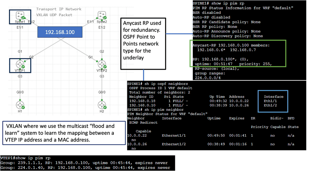
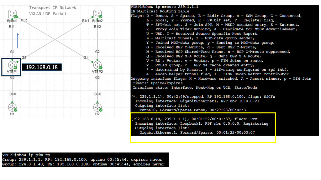
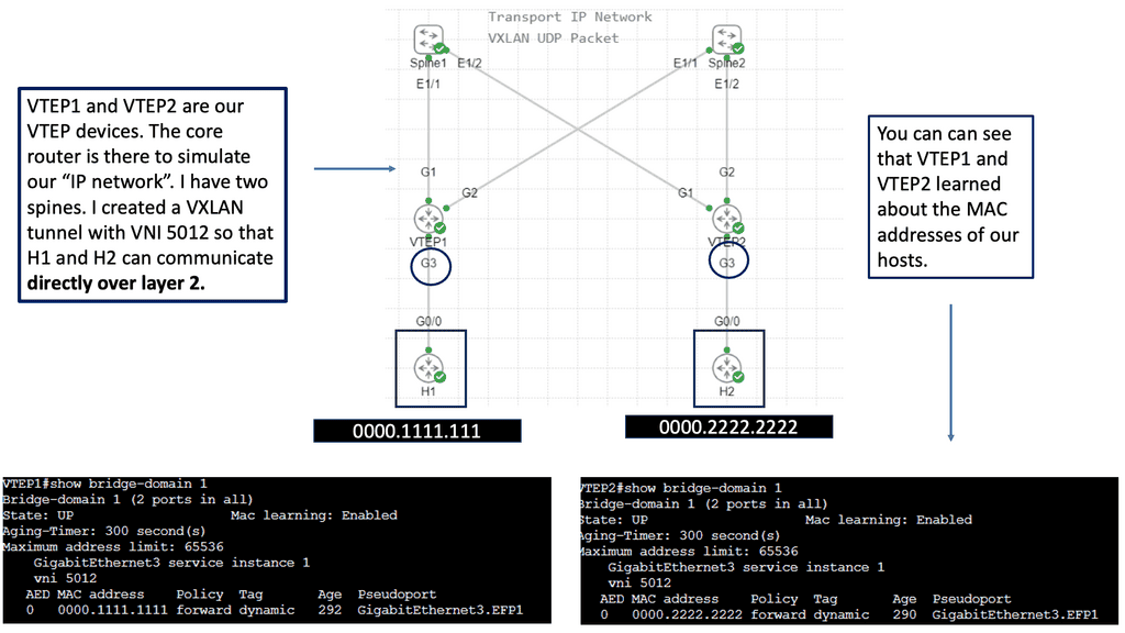
At the core of VXLAN’s architecture are Virtual Tunnel Endpoints (VTEPs). These endpoints are responsible for encapsulating and de-encapsulating packets as they traverse the network. VTEPs can be implemented in both physical and virtual switches, making VXLAN a versatile choice for hybrid network environments. Moreover, the use of a multicast or unicast underlay network ensures that broadcast, unknown unicast, and multicast traffic is efficiently managed.

EVPN MPLS: History
Layer 3 VPNs and MPLS
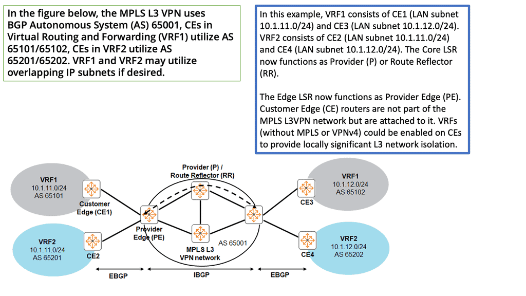
In the late 1990s, we witnessed the introduction of Layer 3 VPNs and Multiprotocol Label Switching (MPLS). Layer 3 VPNs distribute IP prefixes with a control plane, offering any connectivity. So, we have MPLS VPN with PE and CE routers, and EVPN still uses these devices. MPLS also has RD and RT to create different address spaces.
This is also used in EVPN. Layer 3 VPN needed MPLS encapsulation. This signaling was done with LDP; you can use segment routing today. MPLS L3 VPN supports a range of topologies that can be created with Route Targets. Some of which led to complex design scenarios.
Layer 2 VPNs and VPLS
Layer 2 VPNs arrived more humbly with a standard point-to-point connectivity model using Frame Relay, ATM, and Ethernet. Finally, in the early 2000s, pseudowires and layer 2 VPNs arrived. Each of these VPN services operates on different VPN connections, with few working on a Level 3 or MPLS connection. Point-to-point connectivity models no longer satisfied all designs, and services required multipoint Ethernet connectivity.
As a result, Virtual Private LAN Service (VPLS) was introduced. Virtual Private LAN Service (VPLS) is an example of L2VPN and has many drawbacks with using pseudowires to create the topology. A mesh of pseudowires with little control plane leads to much complexity.
VPLS with data plane learning
VPLS offered a data plane learning solution that could emulate a bridge and provide multipoint connectivity for Ethernet stations. It was widely deployed but had many shortcomings, such as support for multi-homing, BUM (BUM = Broadcast, Unknown unicast, and Multicast) optimization, flow-based load balancing, and multipathing. So, EVPN was born to answer this problem.
In the last few years, we have entered a different era of data center architecture with other requirements. For example, we need efficient Layer 2 multipoint connectivity, active-active flows, and better multi-homing capability. Unfortunately, the shortcomings of existing data plane solutions hinder these requirements.
EVPN MPLS: Multi-Homing With Per-Flow Capabilities
Some data centers require Layer 2 DCI (data center interconnect) and active-active flows between locations. Current L2 VPN technologies do not fully address these DCI requirements. A DCI with better multi-homing capability was needed without compromising network convergence and forwarding. Per-flow redundancy and proper load balancing introduced a BGP MPLS-based Ethernet VPN (EVPN) solution.
**No more pseudowires**
With EVPN, pseudowires are no longer needed. All the hard work is done with BGP. A significant benefit of EVPN operations is that MAC learning between PEs occurs not in the data plane but in the control plane (unlike VPLS). It utilizes a hybrid control/data plane model. First, data plane address learning occurs in the access layer.
This would be the CE to PE link in an SP model using IEEE 802.1x, LLDP, or ARP. Then, we have control-plane address advertisements / learning over the MPLS core. The PEs run MP-BGP to advertise and learn customer MAC addresses. EVPN has many capabilities, and its use case is extended to act as the control plane for open standard VXLAN overlays.
L2 VPN challenges
There are several challenges with traditional Layer 2 VPNs. They do not offer an ALL-active per-flow redundancy model, traffic can loop between PEs, MAC flip-flopping may occur, and there is the duplication of BUM traffic (BUM = Broadcast, Unknown unicast, and Multicast).
In the diagram below, a CE has an Ethernet bundle terminating on two PEs: PE1 and PE2. The problem with the pseudowires VPLS data plane learning approach is that PE1 receives traffic on one of the bundle member links. The traffic is sent over the full mesh of PW and eventually learned by PE2. PE2 cannot know if traffic originated on CE1, and PE2 will return it. CEs also get duplicated BUM traffic.
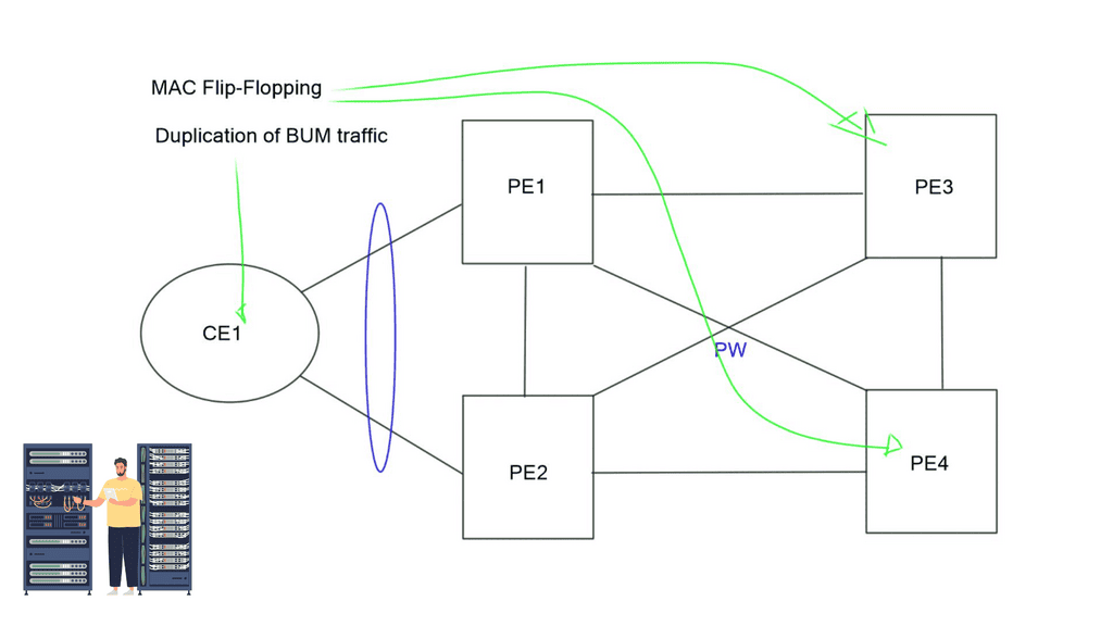
Another challenge with VPLS and L2 VPN is MAC Flip-flopping over pseudowires. Like the above, you have dual-homed CEs sending traffic from the same MAC but with a different IP address. Now, you have MAC address learning by PE1 and forwarded to the remote PE3. PE3 learns that the MAC address is via PE1, but the same MAC with a different flow can arrive via PE2.
PE3 learns the same MAC over the different links, so it keeps flipping the MAC learning from one link to another. All these problems are forcing us to move to a control plane Layer 2 VPN solution – EVPN.
What Is EVPN
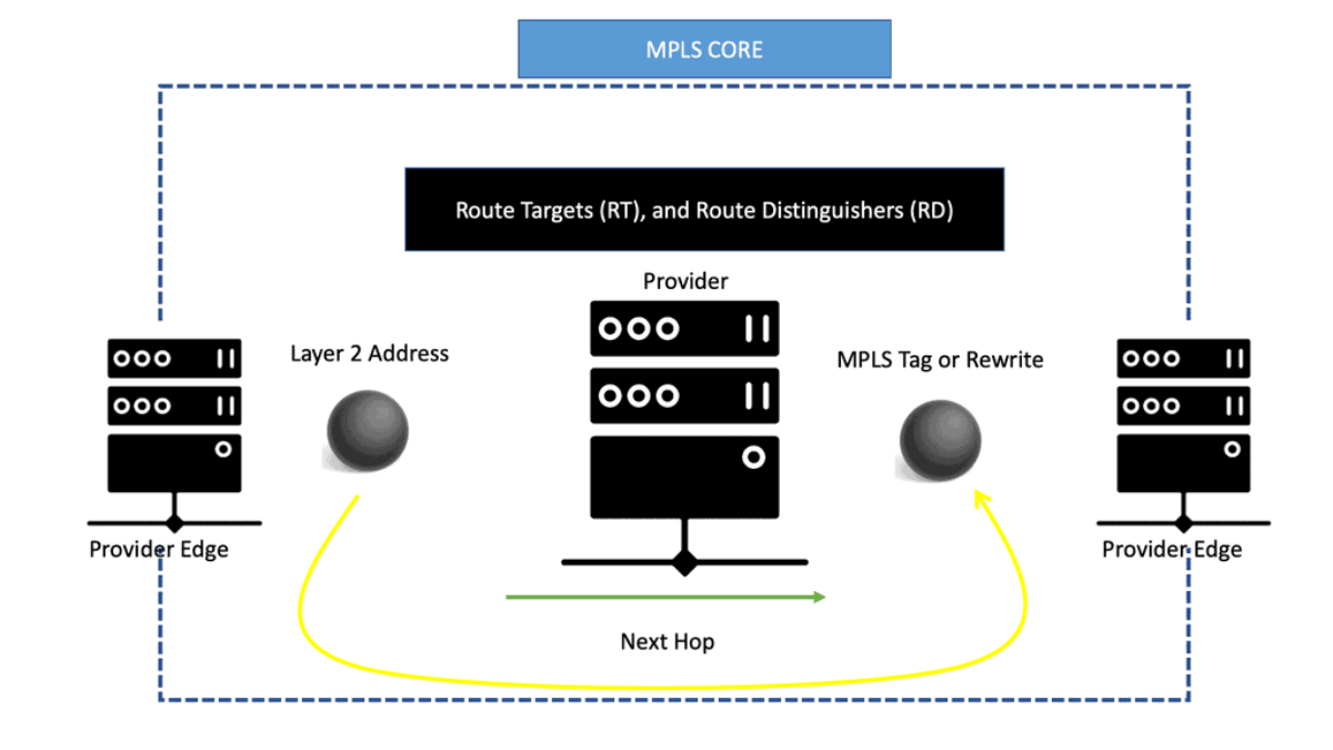
EVPN operates with the same principles and operational experiences as Layer 3 VPNs, such as MP-BGP, route targets (RT), and route distinguishers (RD). EVPN takes BGP, puts a Layer 2 address in it, and advertises as if it were a Layer 3 destination with an MPLS rewrite or MPLS tag as the rewritten header or as the next hop.
It enables the routing of Layer 2 addresses through MP-BGP. Instead of encapsulating an Ethernet frame in IPv4, a MAC address with MPLS tags is sent across the core.
The MPLS core swaps labels as usual and thinks it is another IPv4 packet. This is conceptually similar to IPv6 transportation across an IPv4 LDP core, a feature known as 6PE.

EVPN MPLS: Layer 3 principles apply
All Layer 3 principles apply, allowing you to prepend MAC addresses with RDs to make them unique and permitting overlapping addresses for Layer 2. RTS offers separation, allowing constraints on flooding to interested segments. EVPN gives all your policies with BGP – LP, MED, etc., enabling efficient MAC address flooding control. EVPN is more efficient on your BGP tables; you can control the distribution of the MAC address to the edge of your network.
You control where the MAC addresses are going and where the state is being pushed. It’s a lot simpler than VPLS. You look at the destination MAC address at the network edge and shove a label on it. EVPN has many capabilities. Not only do we use BGP to advertise the reachability of MAC addresses and Ethernet segments, but it may also advertise MAC-to-IP correlation. BGP can provide information that hosts A has this IP and MAC address.
VXLAN & EVPN control plane
Datacenter fabrics started with STP, which is the only thing you can do at Layer 2. Its primary deficiency was that you could only have one active link. We later introduced VPC and VSS, allowing all link forwarding in a non-looped topology. Cisco FabricPath / BGP introduces MAC-in-MAC layer 2 multipathing.
In the gateway area, they added Anycast HSRP, which was limited to 4 gateways. More importantly, they exchanged states.
The industry is moving on, and we now see the introduction of VXLAN as a MAC in IP mechanism. VXLAN allows us to cross a layer 3 boundary and build an overlay over a layer 3 network. Its initial forwarding mechanism was flood and learn, but it had many drawbacks. So now, they have added a control plane to VXLAN—EVPN.
A VXLAN/EVPN solution is an MP-BGP-based control plane using the EVPN NLRI. BGP carries out Layer-2 MAC and Layer-3 IP information distribution. It reduces flooding as forwarding decisions are based on the control plane. The VPN control plane offers VTEP peer discovery and end-host reachability information distribution.
Closing Points on EVPN
Network virtualization has come a long way since its inception. Traditional methods, while effective, often struggled with scalability and flexibility. Enter EVPN, a technology designed to overcome these barriers. By leveraging the power of Border Gateway Protocol (BGP), EVPN provides a multipoint-to-multipoint Layer 2 VPN service, enhancing network performance and efficiency. This evolution reflects a shift towards more dynamic, adaptable networking solutions that cater to the ever-changing demands of businesses.
EVPN offers a myriad of benefits that set it apart from traditional network solutions. Firstly, its ability to support multi-tenancy without compromising security is a game-changer for enterprises. EVPN also simplifies network operations by reducing the need for complex configurations and manual interventions. Additionally, its inherent redundancy and load balancing capabilities ensure high availability and optimal resource utilization. These benefits collectively make EVPN a preferred choice for businesses looking to future-proof their network infrastructure.
At the heart of EVPN’s architecture is its use of BGP for control plane operations, which allows for efficient route distribution and scalability. The EVPN model consists of Provider Edge (PE) routers that communicate through BGP, exchanging reachability information for Layer 2 and Layer 3 services. This architecture not only simplifies network management but also enables seamless integration with existing infrastructures. By decoupling the data plane from the control plane, EVPN provides a flexible framework that supports a wide range of applications and services.
The versatility of EVPN extends into various real-world applications, from data center interconnects to cloud networking. In data centers, EVPN facilitates seamless connectivity and resource sharing, optimizing workload distribution and enhancing operational efficiency. For cloud services, EVPN ensures secure and scalable connectivity across multiple locations, supporting hybrid and multi-cloud environments. These applications highlight EVPN’s role as a critical enabler of modern, agile networking solutions.