
security

Implementing Network Security

ENGINEERING GUIDE · NETWORK SECURITY

IPv4 & IPv6 Network Security — From Packet Filtering to Behavioural Defence

Modern network security is not a single firewall rule or access list. It is a layered control system that determines who can communicate, which traffic is permitted, where trust boundaries exist, how IPv4 and IPv6 behave differently, and how abnormal traffic is detected and investigated.

The Engineering Problem
Allowing connectivity is easy. Controlling communication is the challenge.

Networks must support legitimate application traffic while limiting unwanted access, protecting infrastructure protocols, controlling lateral movement, and maintaining visibility across both IPv4 and IPv6 paths.

01 · CONTROL

Define the Boundary

Identify trust zones, interfaces, identities, services and the traffic that should be permitted between them.

02 · PROTECT

Enforce Policy

Apply ACLs, firewall policy, segmentation and IPv6-specific protections at the points where traffic crosses a security boundary.

03 · OBSERVE

See Behaviour

Combine flow telemetry, packet visibility, DNS, connection metadata and infrastructure events to establish what normal looks like.

04 · RESPOND

Investigate Change

Correlate unusual behaviour with policy, topology and application context to determine whether an event is expected, suspicious or malicious.

Engineering View

Security follows the data flow.

A secure design starts with the communication path: source, destination, protocol, service, trust boundary and enforcement point. IPv6 introduces additional control-plane considerations such as Neighbor Discovery, Router Advertisements and multicast behaviour, while transition technologies introduce their own security boundaries.

Identity

Who or what is attempting the communication?

Policy

Should this source be allowed to reach this destination?

Telemetry

What does the traffic reveal about behaviour and change?

Threat

Does the observed behaviour indicate compromise or abuse?

The engineering question: Can we prove that the traffic we permit is expected, visible and appropriately controlled?
What This Guide Examines
IPv4 ACLs IPv6 ACLs Firewalls Segmentation NDP RA Guard DAD NAT64 NPTv6 GRE & IPsec NetFlow / IPFIX sFlow Threat Detection Incident Investigation
Widget 3 · Visibility & Behaviour

Behavioural Threat Detection Explorer

Security visibility turns network telemetry into intelligence. Explore how traffic patterns can expose beaconing, DNS tunnelling, lateral movement and abnormal east-west activity.

TELEMETRY → INTELLIGENCE
Detection Scenarios LIVE MODEL
Network Behaviour · Simulated Flow
Connections
42
Destinations
3
Pattern
Stable
Detection Engine CORRELATION
BEHAVIOURAL RISK 12
Traffic frequency NORMAL
Destination diversity NORMAL
Protocol behaviour NORMAL
East-west movement NORMAL
Threat correlation NONE
RECOMMENDED RESPONSE
ALLOW
Continue monitoring normal application behaviour.
Education Layer Network-derived intelligence is created by correlating patterns rather than examining a single packet. Frequency, destinations, protocols, identity and east-west behaviour can be combined to identify anomalies.
NETWORK SECURITY LAB

Network Security Control Plane Explorer

Modern network security is not enforced by a single firewall. Identity, segmentation, network controls, application inspection and detection work together to determine whether traffic should be allowed, blocked or isolated.

Security Enforcement Pipeline

POLICY ACTIVE
ID
Identity Validation Validate user identity, device posture and authentication context.
PASS
SG
Network Segmentation Determine whether the source can communicate with the destination segment.
READY
FW
Firewall Policy Evaluate source, destination, protocol, port and security policy.
READY
L7
Application Inspection Inspect application requests, paths and methods where required.
READY
AI
Detection & Analytics Correlate behaviour and telemetry to identify suspicious activity.
READY

Control Analysis

IDENTITY CONTROL

Establish who is requesting access

Identity is the first decision point in a modern security architecture. Authentication, device posture and contextual information establish whether the request can continue through the security pipeline.

Engineering question Can the requesting identity and device be trusted enough to continue?
Security principle Never assume trust simply because a device is already inside the network.
Current decision PASS — Continue Identity requirements are satisfied. Traffic can continue to the next security control.

Security Pipeline Outcome

READY

Select a control above to examine how that layer contributes to the overall network-security decision.

ENGINEERING INTRO · SECTION 01

Security Architecture — Follow the Data Flow

Start with the communication relationship before choosing the security control. Tap a component to see where the trust boundary and enforcement decision belong.

Trust Boundary Explorer
Trust boundary
01 · SOURCE Client
04 · CONTROL Firewall
02 · DESTINATION Service
03 · TRUST Boundary
Current Engineering Question

Who initiates the traffic?

Start at the source. Identify the system initiating the communication before deciding what should be permitted.

1 Identify the source
2 Define the destination
3 Locate the trust boundary
4 Choose the enforcement point
Engineering view: security policy should follow the data flow — not the other way around.
SECTION 01 · DEFINE

Security Architecture & Trust Boundaries

Network security begins before a firewall rule is written. The first task is to understand what is communicating, where trust changes, which traffic is expected, and where that communication can be controlled. This creates the security architecture that later filtering, inspection and monitoring mechanisms enforce.

Engineering Principle
Security policy should follow the data flow.

A useful security model connects the source, destination, application, protocol, trust zone and enforcement point rather than treating the network as a collection of isolated devices.

01 · SOURCE

Who initiates?

Identify the user, endpoint, server, workload or infrastructure device generating the traffic.

02 · DESTINATION

What is reached?

Determine the destination network, host, service or application being accessed.

03 · TRUST

Where does trust change?

Identify the boundary between users, servers, management, Internet, cloud and other security zones.

04 · CONTROL

Where is it enforced?

Place the appropriate ACL, firewall, segmentation or inspection control at the point where it can make the required decision.

Trust Boundaries

A trust boundary is the point at which traffic moves between different security assumptions. The boundary may exist between a user VLAN and server network, between an enterprise and the Internet, or between on-premises infrastructure and a cloud environment.

  • User and endpoint networks
  • Server and application zones
  • Management infrastructure
  • Internet and external services
  • Cloud and hybrid environments

Control Points

Once the boundaries are understood, security controls can be mapped to the traffic path. The objective is not simply to block traffic, but to make the policy decision explicit and observable.

  • Router and Layer 3 ACLs
  • Stateful firewall policy
  • Network segmentation
  • Identity and access controls
  • IDS/IPS and inspection systems
Engineering View

IPv4 and IPv6 must be secured as separate control planes.

A network can appear secure from an IPv4 perspective while IPv6 provides an overlooked path around the intended policy. Security architecture must therefore account for both protocol stacks, their control-plane behaviour, addressing model, routing, neighbour discovery and enforcement mechanisms.

Key takeaway: before deciding what traffic to block, establish what traffic should exist, which boundaries it crosses, and exactly where the security decision should be enforced.
ENGINEERING LAB · SECTION 01 · DEFINE

Trust Boundary Investigation

Follow a communication relationship from source to destination and prove where trust changes, where policy is enforced, and whether IPv4 and IPv6 follow the same security architecture.
INVESTIGATION READY
LIVE SECURITY PATH
IPv4 · EXPECTED
USER / SOURCE ZONE
SECURITY CONTROL ZONE
SERVER / SERVICE ZONE
◉
CLIENT
10.10.10.20
◇
ACCESS
VLAN / L2
▣
POLICY GATE
ACL + FIREWALL
▤
APPLICATION
10.20.10.40
⚠ SECURITY GAP IPv6 traffic reaches the application without crossing the intended policy gate.
TRUST INSPECTOR
LIVE EVIDENCE
CURRENT FINDING
Source identified
Begin the trace by identifying who initiates the communication.
SOURCE
CLIENT
DESTINATION
APPLICATION
PROTOCOL
IPv4
BOUNDARY
NOT YET VERIFIED
CONTROL
ACL + FIREWALL
DECISION
PENDING
DATA-FLOW TRACE
STEP 1 / 4
01
SOURCE
Identify the initiator.
02
DESTINATION
Confirm what is reached.
03
TRUST
Locate the boundary.
04
CONTROL
Prove enforcement.
ENGINEERING READOUT
ARCHITECTURE
SECURITY PRINCIPLE
Security policy should follow the data flow.
ENGINEERING INTRO · SECTION 02

Policy Decisions — Permit the Relationship, Not the Guess

Build a simple security decision by defining who is communicating, what protocol is being used and whether that relationship is actually required.

Build the traffic relationship
SOURCE
DESTINATION
PROTOCOL
RELATIONSHIP REQUIRED?
Security Policy Decision
POLICY REVIEW

Permit only required access

The selected relationship represents an intentional communication path. Enforce it at the appropriate ACL or firewall control point.

Source User
Destination Application
Protocol HTTPS
Control ACL / Stateful Firewall
Engineering principle: every security rule should represent an intentional communication relationship.
SECTION 02 · CONTROL

ACLs, Firewall Policy & Network Segmentation

Once trust boundaries and expected communication flows are defined, the next step is enforcement. ACLs and firewalls provide the decision logic that determines whether traffic is permitted, denied, inspected or logged. Segmentation then limits how far a compromised endpoint or workload can move through the network.

Engineering Principle
Every security rule should represent an intentional communication relationship.

A strong policy is specific about source, destination, protocol, service and direction. Broad rules may restore connectivity quickly, but they also make the security boundary difficult to understand and defend.

01 · FILTER

ACLs

Apply packet-level permit and deny decisions using addresses, prefixes, protocols and ports at routing or interface boundaries.

02 · INSPECT

Stateful Firewalls

Evaluate traffic in the context of connections, zones, applications and security policy rather than treating every packet independently.

03 · CONTAIN

Segmentation

Reduce unnecessary reachability between users, workloads, management systems and sensitive services.

Traffic Flow
Policy Question
Control
Engineering Objective
User → Server IPv4
Is the service required?
ACL / Firewall
Permit only required access
Client → Service IPv6
Does IPv6 follow the same policy?
IPv6 ACL / Firewall
Prevent an unintended alternate path
Server → Database TCP
Is this application relationship expected?
Segmentation
Limit lateral movement
Internet → DMZ External
Which service is intentionally exposed?
Firewall
Minimise attack surface
IPv4 / IPv6 Security

One policy. Two protocol stacks.

Deploying IPv6 does not automatically inherit the security posture of IPv4. IPv6 requires its own filtering and control-plane considerations, including Neighbor Discovery traffic and the protocols required for normal IPv6 operation.

Least Privilege

Reduce reachability before detecting compromise.

Segmentation provides a preventative control. If an endpoint is compromised, limiting which networks and services it can reach can reduce lateral movement before detection and response mechanisms take effect.

Engineering rule: a security policy should be understandable from the traffic flow alone. If nobody can explain why a rule exists, it should be reviewed rather than becoming permanent background configuration.
ENGINEERING LAB · SECTION 02 · CONTROL

Policy Decision Engine

Build a communication relationship and evaluate it against ACL, firewall and segmentation controls. The objective is not simply to permit traffic — it is to prove why that traffic should be permitted.
POLICY ENGINE READY
COMMUNICATION RELATIONSHIP
POLICY INPUT
◉
USER
SOURCE
◇
POLICY
ACL / FIREWALL
▤
APPLICATION
DESTINATION
Policy Rule
Match
Action
Service relationship
TCP/443
MATCH
Network boundary
USER → APP
CHECK
Protocol policy
IPv4
CHECK
DECISION ANALYSIS
ENGINE OUTPUT
SECURITY DECISION
PENDING
Define a source, destination, protocol and service, then evaluate the relationship.
POLICY CONFIDENCE 0%
SOURCE
—
DESTINATION
—
SERVICE
—
CONTROL
—
RATIONALE
—
FILTER
ACL / Stateless Control
Match source, destination, protocol and service. Keep the rule explicit and narrow.
SOURCE + DEST + SERVICE
INSPECT
Stateful Firewall
Evaluate the communication relationship at the security boundary and apply the intended policy.
STATE + POLICY
CONTAIN
Network Segmentation
Reduce unnecessary reachability so that a compromised system has fewer paths to other trust zones.
LIMIT LATERAL MOVEMENT
ENGINEERING INTRO · SECTION 03

IPv6 Control Plane — Follow the Discovery Sequence

IPv6 relies on Neighbor Discovery for router discovery, prefix discovery, address resolution, duplicate-address detection and neighbor reachability. Step through the sequence to see where security controls matter.

IPv6 host configuration sequence
Control-plane inspection
STEP 01 / 05
ROUTER DISCOVERY

Router Advertisement

Router Advertisements provide hosts with information about available IPv6 routers and network configuration. An unexpected RA can therefore influence how hosts configure and route traffic.

Security focus: control unauthorized Router Advertisements.
Engineering principle: protect the IPv6 control plane without breaking the discovery mechanisms that make IPv6 work.
SECTION 03 · PROTECT

IPv6 Control-Plane Security

IPv6 changes more than the address format. Core network functions such as address resolution, router discovery and duplicate-address detection are performed through Neighbor Discovery Protocol (NDP) and IPv6 multicast. These mechanisms are essential to normal operation, but they also create security considerations that do not have a direct IPv4/ARP equivalent.

Engineering Principle
Protect the IPv6 control plane without breaking the mechanisms that make IPv6 work.

Security controls must distinguish legitimate Neighbor Discovery and Router Advertisement traffic from malicious or unexpected control-plane behaviour.

01 · NDP

Neighbor Discovery

Provides neighbour discovery, address resolution, router discovery, prefix discovery and neighbour reachability functions.

02 · RA

Router Advertisements

Hosts learn IPv6 prefixes, default-router information and other configuration parameters through Router Advertisements.

03 · DAD

Duplicate Address Detection

Hosts use Neighbor Solicitation to determine whether an IPv6 address is already in use before assigning it to an interface.

04 · ENFORCE

RA Guard

Layer 2 infrastructure can filter unauthorized Router Advertisements at the access boundary before they reach end hosts.

IPv6 Host Configuration — Control-Plane Sequence
RA Router provides network information
Prefix Host learns the IPv6 prefix
Address Host forms an IPv6 address
DAD Host checks for duplication
Reachability NDP maintains neighbour state
Security Control

RA Guard at the access boundary

An unauthorized device sending Router Advertisements can influence how hosts select default routers or configure their IPv6 connectivity. RA Guard provides a Layer 2 enforcement mechanism that can block unwanted Router Advertisements on access ports while allowing them on trusted router-facing paths.

Threat Consideration

IPv6 attacks can begin with control traffic.

Security monitoring should not focus exclusively on application payloads. Unexpected Router Advertisements, abnormal Neighbor Discovery behaviour, duplicate-address events or unusual IPv6 multicast activity can provide valuable evidence during an investigation.

Key takeaway: IPv6 security includes the control plane. Filtering application traffic is not enough if an attacker can influence neighbour discovery, router discovery or other mechanisms required for normal IPv6 operation.
ENGINEERING LAB · SECTION 03 · PROTECT

IPv6 Control-Plane Investigation

Step through the IPv6 host configuration sequence and identify where Router Advertisements, Neighbor Discovery and Duplicate Address Detection become security-relevant control-plane events.
CONTROL PLANE READY
IPv6 HOST CONFIGURATION SEQUENCE
EVENT 1 / 5
01
⌁
ROUTER DISCOVERY
Host learns about available routers.
02
◇
PREFIX
Prefix information is learned.
03
◉
ADDRESS
The host forms its IPv6 address.
04
◎
DAD
Duplicate address detection runs.
05
⇄
REACHABILITY
Neighbor reachability is established.
CONTROL-PLANE EVENT STREAM
▣
IPv6 ROUTER
fe80::1
▤
IPv6 HOST
fe80::20
ROUTER ADVERTISEMENT
RA RECEIVED The host has received IPv6 router information.
SECURITY INSPECTOR
CONTROL PLANE
CURRENT EVENT
Router Advertisement
Router Advertisements allow hosts to learn about routers, prefixes and other configuration information.
SECURITY QUESTION
Is this router legitimate?
An unexpected RA can influence how hosts select routers and configure IPv6 connectivity.
MESSAGE
ROUTER ADVERTISEMENT
SOURCE
FE80::1
CONTROL
RA GUARD
OBSERVATION
MONITOR
NDP
Neighbor Discovery
IPv6 uses NDP for functions including router discovery, address resolution and neighbor reachability.
NO IPv6 BROADCAST
RA GUARD
Access-Layer Protection
RA Guard can filter unwanted Router Advertisements at an access-layer boundary.
FILTER UNEXPECTED RA
DAD
Address Validation
Duplicate Address Detection uses Neighbor Solicitation to check whether an IPv6 address is already in use.
NS → SOLICITED-NODE MULTICAST
ENGINEERING INTRO · SECTION 04

IPv6 Transition — Choose the Mechanism for the Problem

NAT64, NPTv6 and tunnelling solve different connectivity problems. Select a mechanism to see what changes in the packet path and where the new security boundary appears.

Select mechanism

NAT64 — IPv6 to IPv4 Translation

Protocol Translation
Client IPv6 Host
→
Boundary NAT64
→
Service IPv4 Server
Problem solved IPv6-only clients reaching IPv4 services
Security boundary Translation device and its policy/state
Visibility change Address and protocol context changes across the translator
Security focus Inspect and control the translated path
NAT64 is a translation mechanism for IPv6-to-IPv4 communication. It should not be treated as equivalent to IPv6 prefix translation or tunnelling.
Engineering principle: every transition mechanism changes what the network can see, enforce or troubleshoot. Secure the mechanism as well as the traffic crossing it.
SECTION 04 · TRANSITION

IPv6 Transition, Translation & Tunnelling

IPv4 and IPv6 will often coexist for many years. Security architecture therefore has to account for transition mechanisms as well as native IPv6 traffic. Translation, prefix translation and tunnelling solve different engineering problems and introduce different security boundaries.

Engineering Principle
Do not treat IPv6 transition technologies as interchangeable.

NAT64 provides IPv6-to-IPv4 communication, NPTv6 performs stateless IPv6-to-IPv6 prefix translation, while GRE can encapsulate traffic across an IPv4 underlay. Their security properties and control points are fundamentally different.

01 · TRANSLATE

NAT64

Allows IPv6-only clients to communicate with IPv4-only destinations through an IPv6-to-IPv4 translation function.

IPv6 Client → NAT64 → IPv4 Server
02 · PREFIX

NPTv6

Provides stateless IPv6-to-IPv6 prefix translation. It can be useful for prefix independence or multihoming designs, but it does not provide IPv4/IPv6 interoperability.

IPv6 Prefix A → NPTv6 → IPv6 Prefix B
03 · TUNNEL

GRE + IPsec

GRE can carry IPv6 traffic across an IPv4 transport network. GRE itself does not provide confidentiality; IPsec can be used to protect the encapsulated traffic.

IPv6 Traffic → GRE → IPsec → IPv4 Underlay
Security Boundary

Every translation or tunnel changes what you can see.

A security device may observe the original IPv6 flow, a translated IPv4 flow, or an encapsulated tunnel depending on where inspection occurs. Logging and policy therefore need to identify the correct enforcement point and preserve enough context to reconstruct the original communication.

Operational Design

Secure the transition mechanism itself.

Translation and tunnelling infrastructure should be treated as part of the security architecture. Restrict management access, monitor unusual translation or tunnel activity, apply appropriate filtering and ensure that security policy remains consistent across both sides of the transition boundary.

Important distinction: IPv6 support for IPsec does not mean IPv6 traffic is automatically encrypted. IPsec is a separate security mechanism that must be deliberately configured and applied to the required traffic or tunnel.
ENGINEERING LAB · SECTION 04 · TRANSITION

IPv6 Transition Architecture Explorer

Follow the packet path through NAT64, NPTv6 or GRE + IPsec. The architecture, address family and security boundary change depending on the transition mechanism selected.
NAT64 ARCHITECTURE READY
TRANSITION MECHANISM
SELECT ARCHITECTURE
01
⇄
NAT64
IPv6-only clients communicate with IPv4 services.
02
⇆
NPTv6
Stateless IPv6-to-IPv6 prefix translation.
03
◈
GRE + IPsec
IPv6 traffic carried through an IPv4 underlay.
LIVE PACKET PATH
▣
IPv6 CLIENT
2001:db8:10::20
◆
NAT64
TRANSLATION BOUNDARY
▤
IPv4 SERVER
192.0.2.40
IPv6 PACKET
TRANSLATION EVENT IPv6 traffic crosses a NAT64 translation boundary before reaching an IPv4 destination.
SECURITY INSPECTOR
ARCHITECTURE ANALYSIS
CURRENT TECHNOLOGY
NAT64
Protocol translation provides IPv6-only clients with access to IPv4 services. The translation point becomes an important security and visibility boundary.
ENGINEERING WARNING
Translation changes visibility
Security controls and telemetry must account for both sides of the translation boundary.
MECHANISM
NAT64
ADDRESSING
IPv6 → IPv4
BOUNDARY
TRANSLATION
SECURITY
INSPECT BOTH SIDES
NAT64
IPv6 → IPv4 Interoperability
Used when an IPv6-only client needs to reach an IPv4 service. The translation device becomes a significant policy and telemetry boundary.
DIFFERENT ADDRESS FAMILIES
NPTv6
IPv6 Prefix Translation
NPTv6 translates one IPv6 prefix to another IPv6 prefix. It is not an IPv4/IPv6 interoperability mechanism.
IPv6 → IPv6 · STATELESS
GRE + IPsec
Tunnel + Protection
GRE can carry IPv6 traffic across an IPv4 underlay. GRE itself provides no confidentiality; IPsec can protect the encapsulated traffic.
TUNNEL ≠ ENCRYPTION
ENGINEERING INTRO · SECTION 05

Security Visibility — Choose the Evidence

Different telemetry sources answer different questions. Select an evidence source to see what it can establish, what it cannot prove, and how it contributes to an investigation.

Select evidence source

NetFlow / IPFIX

FLOW EVIDENCE
Can establish Who communicated, which ports were used, protocol, volume and timing.
Best question Which systems communicated and did the traffic pattern change?
Limitation Flow records normally do not provide the full packet payload.
Investigation use Establish a communication baseline and identify unusual flows.
Evidence value HIGH
Flow evidence is particularly useful for understanding communication relationships at scale.
Engineering principle: visibility is not the same as collecting more data. The useful question is whether the evidence can answer the investigation question.
SECTION 05 · OBSERVE

Network Telemetry & Security Visibility

Prevention alone cannot establish whether a network is behaving as expected. Security operations require evidence from multiple visibility layers: flow records, packet observations, infrastructure telemetry, connection metadata and security events. The objective is to turn raw network activity into an evidence trail that can be investigated.

Engineering Principle
Visibility is not the same as collecting more data.

Effective monitoring means collecting the right evidence at the right observation point and correlating it with topology, identity, policy and application context.

01 · FLOW

NetFlow / IPFIX

Provides flow metadata such as endpoints, ports, protocol, byte counts, packet counts and timing information.

02 · SAMPLE

sFlow

Uses sampling to provide scalable visibility into traffic behaviour and interface activity across large networks.

03 · PACKET

SPAN / Capture

Provides packet-level evidence for deeper protocol analysis and investigation when flow metadata is insufficient.

04 · EVENT

Security Telemetry

Firewall, IDS/IPS, DNS, authentication and endpoint events add context around network behaviour and policy decisions.

What the Network Can Tell You

Flow and telemetry systems may not expose application payloads, but they can still reveal important behavioural signals.

Endpoints Who is communicating with whom?
Ports Which services or protocols are involved?
Volume Has traffic volume changed significantly?
Timing When does the communication occur?

Encrypted Traffic Still Leaves Signals

Encryption protects payload content, but network communication still produces observable metadata. Traffic volume, packet sizes, timing, destinations, connection frequency and DNS activity can contribute to behavioural analysis.

Metadata Addresses, ports and connection patterns remain visible.
Baseline Normal application behaviour provides comparison.
Deviation Unexpected patterns can become investigation signals.
Correlation Multiple weak signals can form stronger evidence.
Engineering Evidence Chain

Observe → Correlate → Baseline → Investigate

A useful security monitoring architecture does not stop at collecting telemetry. Evidence becomes valuable when network observations can be correlated with infrastructure state, identity, policy and application behaviour.

OBSERVE Collect traffic and infrastructure signals.
CORRELATE Connect events across systems and time.
BASELINE Understand expected behaviour.
INVESTIGATE Explain meaningful deviations.
Key takeaway: a security platform becomes more useful when telemetry can answer not only what happened, but also where it happened, what changed, and whether the behaviour was expected.
ENGINEERING LAB · SECTION 05 · OBSERVE

Network Telemetry & Security Evidence Lab

Select a telemetry source, inspect the evidence it provides, then correlate the observation to determine what the network can actually prove.
FLOW TELEMETRY SELECTED
TELEMETRY SOURCES
SELECT EVIDENCE TYPE
01
⇄
NetFlow / IPFIX
Endpoints, ports, protocol, bytes, packets and timing.
02
◌
sFlow
Sampling-based visibility for scalable traffic monitoring.
03
◈
Packet Capture
Packet-level evidence for detailed protocol investigation.
04
!
Security Events
Firewall, IDS/IPS, DNS, authentication and endpoint events.
OBSERVED NETWORK EVIDENCE 01 / 04
SOURCE
10.10.20.15
OBSERVED
DESTINATION
10.20.40.30
OBSERVED
PROTOCOL
TCP / 443
OBSERVED
PATTERN
184 MB / 12 MIN
SIGNAL
EVIDENCE CORRELATION
WHAT CAN WE PROVE?
CORRELATION CONFIDENCE
Current evidence strength
25%
CURRENT FINDING
A communication relationship exists.
Flow telemetry can establish who communicated, where they communicated and characteristics such as protocol, volume and timing.
VISIBILITY LIMIT
Flow records do not provide the complete packet payload. Additional evidence may be required.
FLOW
Metadata at Scale
Strong for endpoint relationships, ports, traffic volume, timing and behavioural baselines.
NETFLOW / IPFIX
SAMPLE
Scalable Observation
Sampling provides broad visibility without requiring every packet to be captured.
SFLOW
PACKET
Detailed Evidence
Packet capture can reveal protocol-level details unavailable from flow records alone.
SPAN / CAPTURE
EVENT
Security Context
Firewall, IDS/IPS, DNS, authentication and endpoint events add investigative context.
CORRELATE
ENGINEERING INTRO · SECTION 06

Behavioural Threat Detection — Investigate the Change

A security event becomes meaningful when it can be compared with normal behaviour. Step through the investigation from baseline to correlated evidence and determine whether the change needs investigation.

Investigation workflow
01
Baseline Understand the normal communication pattern.
02
Detect Identify a meaningful deviation.
03
Correlate Connect multiple independent signals.
04
Investigate Decide whether the change is expected or suspicious.
Investigation evidence
BASELINE
NORMAL BEHAVIOUR

Establish the baseline

The first question is not "is this malicious?" It is whether the observed communication differs from the expected operating pattern.

Observed User → Application over HTTPS
Signal Stable daily pattern
Current conclusion
No deviation established yet. Continue observing the baseline.
Engineering principle: incidents are often detected as changes in behaviour. Baseline first, then correlate the evidence before deciding what happened.
SECTION 06 · INVESTIGATE

Behavioural Threat Detection

Traditional security controls are designed around known policy: permitted destinations, approved services, trusted systems and expected communication paths. Behavioural detection adds another question: does the observed behaviour match the normal operating pattern? This allows security teams to identify suspicious change even when no single packet or rule violation provides the complete answer.

Engineering Principle
Security incidents are often detected as changes in behaviour.

A useful detection model establishes a baseline, identifies meaningful deviations and correlates several weak signals before escalating an event into an investigation.

01 · BASELINE

Know Normal

Understand normal hosts, services, destinations, traffic volumes and communication patterns.

02 · DETECT

Find Change

Identify unusual communication, volume, timing, destinations or access patterns.

03 · CORRELATE

Build Evidence

Combine network, DNS, identity, endpoint and security telemetry to strengthen the signal.

04 · INVESTIGATE

Explain the Change

Determine whether the deviation is expected activity, misconfiguration or evidence of compromise.

Behavioural Signals

Individual observations are rarely enough to establish an incident. Their value increases when several signals point toward the same behavioural change.

Scanning One host contacting an unusual number of destinations or ports.
Lateral Movement New east-west communication between systems that normally do not interact.
Command & Control Repeated outbound connections or unusual destination patterns may warrant investigation.
Data Movement Unexpected changes in transfer volume, destination or communication timing.

IPv4 & IPv6 Behaviour

Dual-stack environments create another investigation dimension. Security teams must determine whether IPv4 and IPv6 exhibit the same expected communication relationships.

IPv4 Path Is the expected IPv4 security policy being enforced?
IPv6 Path Does IPv6 expose an alternate route or service?
NDP Activity Are neighbour and router-discovery events consistent with the topology?
Correlation Does the same host behaviour appear across both protocol stacks?
Engineering Investigation Loop

Baseline → Detect → Correlate → Validate → Respond

Behavioural detection should produce an explainable evidence chain rather than an isolated alert. The investigator starts with the deviation, identifies the affected systems and communication paths, then validates whether the observed behaviour is expected before taking containment or response action.

BASELINE What normally happens?
DETECT What changed?
CORRELATE What other evidence supports it?
VALIDATE Is the activity legitimate?
RESPOND What control should change?
Key takeaway: behavioural security is not simply about generating more alerts. The goal is to identify meaningful changes, connect them to the network data flow and produce enough evidence to explain whether the behaviour represents normal activity, misconfiguration or a genuine security event.
ENGINEERING LAB · SECTION 06 · INVESTIGATE

Behavioural Threat Investigation Console

Security incidents often appear first as changes in behaviour. Build the investigation from baseline to detection, correlation and validation instead of treating a single alert as proof.
BASELINE ESTABLISHED
INVESTIGATION WORKFLOW
BUILD THE EVIDENCE
01
◉
Baseline
Establish expected behaviour.
02
!
Detect
Identify meaningful change.
03
⛓
Correlate
Connect independent signals.
04
◈
Investigate
Explain the observed change.
LIVE INCIDENT TIMELINE
09:10
Normal traffic baseline
Host normally communicates with a small set of internal services over predictable ports.
09:42
New destination observed
The host begins communicating with an endpoint outside its established behavioural baseline.
09:44
IPv6 activity increases
IPv6 flows and NDP activity appear alongside the changed communication pattern.
09:48
Cross-source correlation
Flow telemetry and security events independently support the behavioural deviation.
THREAT ASSESSMENT
CURRENT CONFIDENCE
BEHAVIOURAL SIGNAL
Change detected
A communication pattern has deviated from the established operating baseline.
INVESTIGATION CONFIDENCE
20%
CURRENT FINDING
Baseline established — no incident proven.
A baseline tells the investigator what normal looks like. The next question is whether the observed change is meaningful.
1 · Expected? Is the changed communication part of a legitimate operational activity?
2 · Correlated? Do independent telemetry sources show the same change?
3 · Explained? Can the behaviour be explained by configuration, maintenance or application activity?
SCANNING
Many Destinations
A sudden increase in destination diversity can represent reconnaissance or legitimate discovery activity.
DESTINATION CHANGE
LATERAL MOVEMENT
New Internal Paths
Unexpected east-west communication can indicate a change in the host's normal trust relationships.
EAST-WEST
C2 SIGNAL
Repeated Behaviour
Repeated timing, destination or connection patterns may become significant when correlated with other evidence.
PERIODICITY
DATA MOVEMENT
Volume Deviation
Unusual transfer volume or timing can provide another signal when compared with the established baseline.
VOLUME CHANGE
ENGINEERING INTRO · SECTION 07

Response Decisions — Automate What You Understand

Detection does not automatically justify containment. Select the confidence level and see how the response should become more controlled as evidence becomes stronger.

Evidence confidence

Validate Before Acting

LOW CONFIDENCE
01 Detect
02 Validate
03 Contain
04 Verify
05 Recover
CONTROLLED RESPONSE

Investigate — Do Not Automatically Contain

A single signal is not enough to justify a disruptive policy change. Gather additional evidence and validate the event first.

Recommended action Correlate telemetry and investigate
Automation boundary Human validation required
Engineering principle: automate the response that is understood — not the uncertainty.
SECTION 07 · RESPOND

Security Operations & Automated Response

Detection becomes valuable when it can drive a controlled response. Security operations connect the investigation evidence from the previous sections with enforcement systems such as firewalls, IDS/IPS, access controls, routing policy and endpoint controls. The objective is not to automate every decision, but to make response consistent, explainable and repeatable.

Engineering Principle
Automate the response that is understood — not the uncertainty.

High-confidence, well-defined actions can be automated. Ambiguous events should retain a human investigation step before disruptive controls are applied.

01 · DETECT

IDS / IPS

Identify suspicious traffic and, where appropriate, apply prevention or blocking controls.

02 · CONTAIN

Segmentation

Reduce the reachable attack surface by isolating affected systems or communication paths.

03 · ENFORCE

Policy Change

Update firewall, ACL, routing or access policy when evidence justifies a change.

04 · RECOVER

Restore State

Remove temporary controls and confirm that normal, validated behaviour has returned.

Response Decisions

Response should be proportional to confidence and impact. A suspicious signal does not automatically justify a disruptive network change.

LOW CONFIDENCE Collect additional telemetry and continue investigation.
MEDIUM Increase monitoring, restrict exposure or request analyst validation.
HIGH CONFIDENCE Apply a defined containment action with an auditable change record.
CRITICAL Execute approved emergency containment and escalate immediately.

Human + Automation

Automation is most effective when it operates inside clearly defined guardrails rather than replacing engineering judgement.

TRIGGER A detection reaches a defined confidence threshold.
VALIDATE Confirm affected asset, communication path and policy context.
EXECUTE Apply the approved response through a controlled automation workflow.
AUDIT Record what changed, why it changed and what evidence triggered it.
Engineering Response Loop

Detect → Validate → Contain → Verify → Recover

Automation platforms such as Ansible Automation Platform can orchestrate repeatable operational actions across network and security infrastructure. The important engineering control is the workflow around the automation: evidence, approval boundaries, execution, verification and rollback.

DETECT Identify a meaningful security event.
VALIDATE Confirm the evidence and affected scope.
CONTAIN Apply the minimum required control.
VERIFY Confirm the threat path is controlled.
RECOVER Return the environment to a known-good state.
Key takeaway: effective security operations connect detection to controlled action. The strongest response architecture combines telemetry, human judgement, policy enforcement and automation without allowing an uncertain detection to trigger an uncontrolled network change.
ENGINEERING LAB · SECTION 07 · RESPOND

Security Response Decision Engine

Choose the evidence confidence and proposed response. The engine determines whether the action can be automated, requires human approval, or should remain under investigation.
LOW CONFIDENCE · HOLD
RESPONSE POLICY BUILDER
SELECT CONFIDENCE + ACTION
01
LOW
Weak or incomplete evidence.
02
MEDIUM
Suspicious but requires context.
03
HIGH
Correlated evidence supports action.
04
CRITICAL
Immediate controlled containment.
Monitor
Increase observation without changing network state.
Segment
Restrict communication through a controlled boundary.
Policy Change
Modify a firewall or access-control policy.
Isolate
Apply immediate containment to the affected system.
RESPONSE CONTROL LOOP
DETECT
VALIDATE
EXECUTE
DECISION OUTPUT
POLICY EVALUATION
RECOMMENDED CONTROL
Hold action
Evidence is insufficient for an automated network change. Continue observation and gather additional context.
AUTOMATION: BLOCKED
CONFIDENCE
LOW
ACTION
MONITOR
APPROVAL
REQUIRED
ROLLBACK
AVAILABLE
AUTOMATE THE RESPONSE THAT IS UNDERSTOOD
A suspicious signal should not automatically become a destructive policy change. Validate first.
DETECT
Identify the Signal
Use telemetry and security events to establish what changed before deciding what should happen next.
EVIDENCE
VALIDATE
Confirm the Context
Check whether the behaviour is expected, authorised or already explained by an operational change.
HUMAN JUDGEMENT
EXECUTE
Apply Controlled Action
Automation can apply known response procedures when the evidence and action boundaries are well understood.
AUTOMATION
RECOVER
Verify & Roll Back
Confirm the desired state and preserve a rollback path when changing security policy.
AUDIT / ROLLBACK
ENGINEERING INTRO · SECTION 08

Continuous Security — Validate the Network You Actually Have

Security controls drift as networks change. Explore the assurance loop and see how expected data flows are compared with observed reality across IPv4 and IPv6.

Continuous assurance loop
Current stage MAP

Map the Expected Flow

ASSURANCE 01
DEFINE THE MODEL

Understand the communication relationship

Before validating security, establish which systems should communicate, across which protocol stack and through which control points.

Validation question What communication should exist?
Security focus Define the intended data flow.
IPv4 / IPv6 Model both protocol paths.
Drift signal Unexpected path or service.
Engineering principle: security controls must be continuously validated against the data flow, not simply assumed to remain correct after deployment.
SECTION 08 · VALIDATE

Continuous Security & Assurance

Network security is not a configuration that is completed once and then forgotten. Networks change, applications move, policies evolve and new IPv4 and IPv6 paths appear. Continuous security assurance validates that the intended communication model still matches the observed environment.

Engineering Principle
Security controls must be continuously validated against the data flow.

A policy can be syntactically correct while still being ineffective. Assurance therefore compares intended reachability, enforced controls and observed behaviour.

01 · MAP

Understand the Flow

Identify systems, services, trust boundaries and the communication paths that should exist.

02 · CHECK

Validate Policy

Confirm ACLs, firewalls, segmentation and IPv6 controls enforce the intended relationships.

03 · OBSERVE

Compare Reality

Use telemetry to determine whether actual communication matches the expected security model.

04 · IMPROVE

Close the Gap

Remove unnecessary reachability, improve visibility and update controls as the environment changes.

Continuous Validation Questions

Assurance should turn security policy into measurable engineering questions rather than relying only on configuration review.

REACHABILITY Can systems communicate with destinations they should not reach?
POLICY Does the enforced policy match the documented requirement?
VISIBILITY Can the resulting traffic be observed and investigated?
DUAL STACK Does IPv6 introduce a path that bypasses an IPv4 control?

Security Drift

Security drift occurs when the environment gradually moves away from the intended security model. This can happen through new applications, firewall changes, temporary exceptions, topology changes or previously unknown IPv6 connectivity.

NEW PATH A previously unseen communication relationship appears.
NEW SERVICE A service becomes reachable without an approved requirement.
POLICY GAP A control exists on one protocol stack but not the other.
VISIBILITY GAP Traffic exists but cannot be adequately investigated.
Engineering Assurance Loop

Model → Enforce → Observe → Compare → Improve

The strongest security architecture continuously compares the intended network model with observed behaviour. This turns security from a static collection of rules into an engineering feedback loop.
MODEL Define expected communication and trust.
ENFORCE Apply policy at the appropriate control points.
OBSERVE Collect evidence from actual traffic.
COMPARE Find deviations from the intended model.
IMPROVE Reduce exposure and strengthen controls.
Key takeaway: effective network security is a continuous engineering process. Define the expected data flow, enforce the required controls, observe what actually happens, investigate deviations and continuously validate the security model across both IPv4 and IPv6.
ENGINEERING LAB · SECTION 08 · VALIDATE

Continuous Security Assurance Lab

Compare the intended security model with observed network behaviour. Select a drift condition to see how a change in reachability, service exposure, policy or visibility affects assurance.
SECURITY POSTURE · ASSURED
SECURITY ASSURANCE MODEL
MODEL → ENFORCE → OBSERVE → COMPARE → IMPROVE
CONTROL LIFECYCLE
01
MODEL
Define expected flow
02
ENFORCE
Apply policy
03
OBSERVE
Collect evidence
04
COMPARE
Find deviations
05
IMPROVE
Close the gap
SELECT AN OBSERVED CHANGE
DRIFT-01
New Path
A previously unseen IPv4 or IPv6 communication path appears.
DRIFT-02
New Service
A service becomes reachable outside the intended model.
DRIFT-03
Policy Gap
Observed communication is not represented by an explicit rule.
DRIFT-04
Visibility Gap
Expected traffic exists but monitoring evidence is incomplete.
MODEL
INTENDED
OBSERVED
PATH
Defined
Additional path detected
POLICY
Explicit
Review required
VISIBILITY
Observable
Correlation required
ASSURANCE RESULT
CONTINUOUS VALIDATION
SECURITY ASSURANCE
82%
ASSURED
CURRENT FINDING
Communication path requires validation
The observed environment contains a path that should be compared against the intended communication model.
IPv4 POLICY
ALIGNED
IPv6 POLICY
ALIGNED
OBSERVABILITY
AVAILABLE
DRIFT
DETECTED
VALIDATE BEFORE CHANGING POLICY
A deviation is evidence for investigation, not automatic proof that the existing policy is wrong.
REACHABILITY
Can It Communicate?
Validate whether the observed IPv4 and IPv6 paths match the intended communication relationships.
DATA FLOW
POLICY
Is It Explicit?
Every expected relationship should map to an understandable ACL, firewall, segmentation or access-control decision.
ENFORCEMENT
VISIBILITY
Can We Prove It?
Flow, packet, security and infrastructure telemetry should provide enough evidence to explain important changes.
EVIDENCE
DUAL STACK
Check Both Paths
IPv6 must not become an unintended alternate route around an IPv4 security policy.
IPV4 + IPV6
```
☕
Support Network Insight
Help support independent engineering guides, interactive networking tools, and future learning labs.
Support Network Insight ```
Premium Blog Scenario11.001

Zero Trust Network Design

Zero Trust Network Design

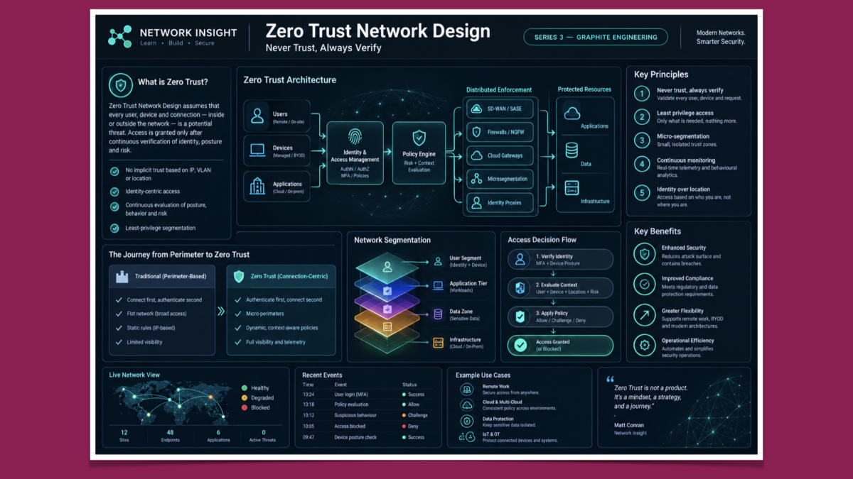
Modern organizations no longer operate within a clearly defined network perimeter. Applications are distributed across data centres, public and private clouds, SaaS platforms, and branch environments, while users and devices connect from offices, homes, mobile networks, and unmanaged locations. In this environment, simply separating the internal network from the Internet is not enough. Zero Trust Network Design provides an architectural approach that assumes access must be explicitly verified rather than automatically trusted because a user or device is connected to an internal network.

The central principle of Zero Trust is straightforward: no user, device, application, or network connection should receive implicit trust. Access decisions are made using information such as identity, authentication strength, device posture, application context, location, resource sensitivity, and other available security signals. Authentication establishes who or what is requesting access, while authorization determines what that identity or device is actually permitted to access.

A major objective is reducing the potential attack surface and limiting the impact of compromised accounts or devices. Instead of providing broad network access once a user has authenticated, Zero Trust encourages least-privilege access to specific applications, services, and resources. This makes unauthorized access more difficult and can significantly reduce lateral movement if an attacker gains control of an account or endpoint.

Identity and Access Management is therefore a fundamental component. Strong authentication, multi-factor authentication, centralized identity, role-based access, conditional policies, and lifecycle management help establish a reliable foundation for access decisions. Identity alone, however, is not sufficient. A valid account can still be compromised, which is why modern Zero Trust architectures combine identity with additional context.

Device security and posture provide another important signal. An access decision can consider whether a device is managed, patched, encrypted, running approved security software, or otherwise meeting organizational requirements. A valid user connecting from a non-compliant device may therefore receive restricted access or be denied access entirely.

Network segmentation and micro-segmentation reduce the ability of an attacker to move freely between systems. Resources can be separated according to application, workload, sensitivity, or business function, with explicit policies controlling communication between them. Segmentation is particularly important in environments containing servers, containers, virtual machines, cloud workloads, and critical business applications.

Continuous monitoring and analytics provide the visibility required to make Zero Trust operational. Authentication events, endpoint telemetry, network flows, application activity, DNS requests, and security events can be correlated to identify unusual behaviour. Access decisions can then be evaluated against changing conditions rather than being treated as permanent permissions.

The security benefits extend beyond preventing unauthorized access. By applying least privilege, segmentation, and continuous verification, organizations can reduce lateral movement and limit the potential impact of compromised credentials or endpoints. Zero Trust also provides a more structured way to control access to sensitive applications and data across increasingly distributed environments.

Zero Trust can also support modern working practices. Remote users, contractors, mobile devices, BYOD environments, cloud applications, and geographically distributed teams do not necessarily need to be placed on a traditional corporate network simply to reach an application. Access can instead be provided to the specific resources required, subject to identity, device, and contextual policies.

Implementing Zero Trust is an architectural transformation rather than the deployment of a single security product. Organizations should begin by understanding their existing users, devices, applications, workloads, data, network flows, and existing access relationships. This provides the visibility required to identify excessive permissions, unnecessary network paths, and high-value resources that require stronger controls.

The next step is to establish appropriate trust boundaries and access policies. These boundaries should be based on applications, workloads, identities, and data sensitivity rather than relying exclusively on traditional network locations. Policies should define who can access a resource, from which devices, under what conditions, and with what level of privilege.

Technology selection should then support those policies. Depending on the environment, this can include identity and access management, multi-factor authentication, endpoint security, network segmentation, micro-segmentation, secure access technologies, firewalls, security analytics, and data protection controls. The objective is not to accumulate security products, but to create a consistent access-control architecture.

A successful Zero Trust design should also be introduced incrementally. Critical applications and high-value data can be prioritized first, with access policies tested and monitored before broader enforcement. This allows organizations to identify operational dependencies and avoid disrupting legitimate business activity while progressively reducing unnecessary access.

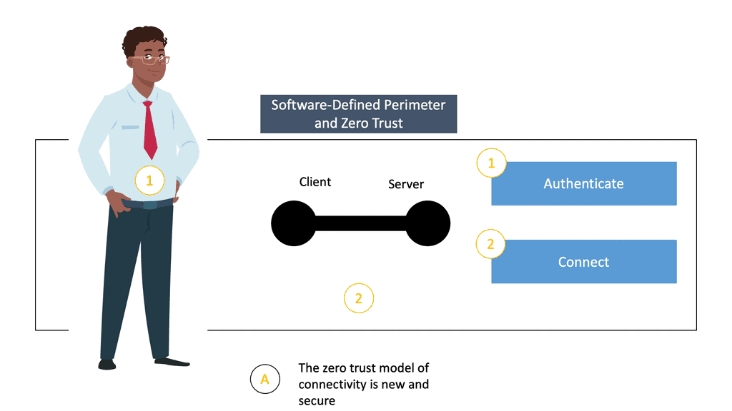
Zero Trust ultimately changes the question from “Is this user inside the network?” to “Should this user, device, and application be allowed to access this specific resource under the current conditions?” That shift is fundamental to securing modern distributed environments. Zero Trust is therefore best understood not as a single technology, but as a security architecture built around explicit verification, least privilege, segmentation, continuous visibility, and adaptive access decisions.

Interactive Security Lab / Series 03

Zero Trust Access Decision Lab

Should this request be trusted? Change identity, device posture and risk signals. Evaluate the request and inspect how a Zero Trust policy determines the next action.

01 / VERIFYIdentity
02 / ASSESSDevice posture
03 / EVALUATEContext and risk
04 / ENFORCEAccess decision

Request Simulator

Configure a connection attempt to a protected application.

Normal behaviourHigh anomaly

Policy Decision

The simulated policy engine explains the decision and its enforcement response.

CURRENT DECISION ALLOW
Illustrative trust score 92
Observed risk score 15

Decision signals

Enforcement response

Highlights: Zero Trust Network Design

**Understanding Zero Trust**

Zero trust is a security concept that challenges the traditional perimeter-based network security model. It operates on the principle of never trusting any user or device, regardless of their location or network connection. Instead, it continuously verifies and authenticates every user and device attempting to access network resources.

Key Points:

A – Certain principles must be followed to implement a zero-trust network design successfully. One crucial principle is the principle of least privilege, where users and devices are granted only the necessary access to perform their tasks. Another principle is continuously monitoring and assessing all network traffic, ensuring that any anomalies or suspicious activities are detected and responded to promptly.

B – Implementing a zero-trust network design requires careful planning and consideration. It involves a combination of technological solutions, such as multi-factor authentication, network segmentation, encryption, and granular access controls. Additionally, organizations must establish comprehensive policies and procedures to govern user access, device management, and incident response.

C – Zero trust network design offers several benefits to organizations. Firstly, it enhances overall security posture by minimizing the attack surface and preventing lateral movement within the network. Secondly, it provides granular control over network resources, ensuring that only authorized users and devices can access sensitive data. Lastly, it simplifies compliance efforts by enforcing strict access controls and maintaining detailed audit logs.

Core Principle — Trust No Network, Verify Every Entity

Traditional networks rely on perimeter firewalls and internal trust zones. Zero Trust eliminates this model.

Every packet, every flow, every identity must be validated continuously.

Zero Trust network design enforces:

  • No implicit trust based on IP, VLAN, or physical location
  • Identity‑centric access instead of network‑centric access
  • Continuous evaluation of posture, behavior, and risk
  • Least‑privilege segmentation across all workloads

This transforms the network from a flat, perimeter‑based environment into a dynamic, identity‑driven security fabric.

Micro‑Segmentation — Breaking the Network Into Secure Zones

Zero Trust network design relies heavily on segmentation. Instead of large L2/L3 domains, the network is divided into small, tightly controlled segments:

  • workload segments
  • user segments
  • application tiers
  • sensitive data zones
  • cloud VPC/VNet segments

Each segment has explicit policies defining which identities can communicate and under what conditions.

This prevents lateral movement — attackers cannot pivot across the network even if they compromise one endpoint.

Identity‑Aware Access Paths

Zero Trust replaces IP‑based access with identity‑aware access.

Policies evaluate:

  • user identity
  • device health
  • authentication strength
  • geolocation
  • behavioral anomalies
  • application sensitivity

This ensures that access is granted based on who the user is and how their device behaves, not where they are located.

Inline Enforcement — Distributed Policy Engines

Zero Trust network design uses distributed enforcement points across:

  • SD‑WAN edges
  • SASE PoPs
  • firewalls and NGFW
  • cloud gateways
  • microsegmentation agents
  • identity‑aware proxies

These enforcement points apply policies consistently across branch, cloud, and data‑center environments.

Instead of a single perimeter firewall, Zero Trust uses many small enforcement nodes, each validating identity and context.

Zero Trust for Hybrid and Multi‑Cloud Networks

Modern networks span:

  • on‑prem data centers
  • public cloud (AWS, Azure, GCP)
  • SaaS platforms
  • remote users
  • branch sites

Zero Trust network design ensures consistent segmentation and access control across all environments.

Policies follow the identity, not the network boundary.

This creates a unified security posture across hybrid and multi‑cloud architectures.

Outcome — A Network Designed for Breach Containment

Zero Trust network design assumes breaches will happen — and builds the network to contain them.

The architecture ensures:

  • attackers cannot move laterally
  • identities cannot escalate privileges
  • compromised devices lose access immediately
  • sensitive workloads remain isolated
  • access is always contextual and verified

Zero Trust becomes the foundation for secure cloud adoption, remote work, and modern distributed architectures.

Telemetry‑Driven Policy Decisions

Zero Trust relies on continuous telemetry from:

  • DNS
  • identity providers
  • endpoint posture
  • network flows
  • cloud access logs
  • behavioral analytics

Policies adapt dynamically based on risk.

If posture degrades or behavior becomes suspicious, Zero Trust can:

  • isolate the session
  • force re‑authentication
  • restrict access
  • block the identity entirely

This makes Zero Trust a living system, not a static configuration.

Modern Zero Trust Network Design

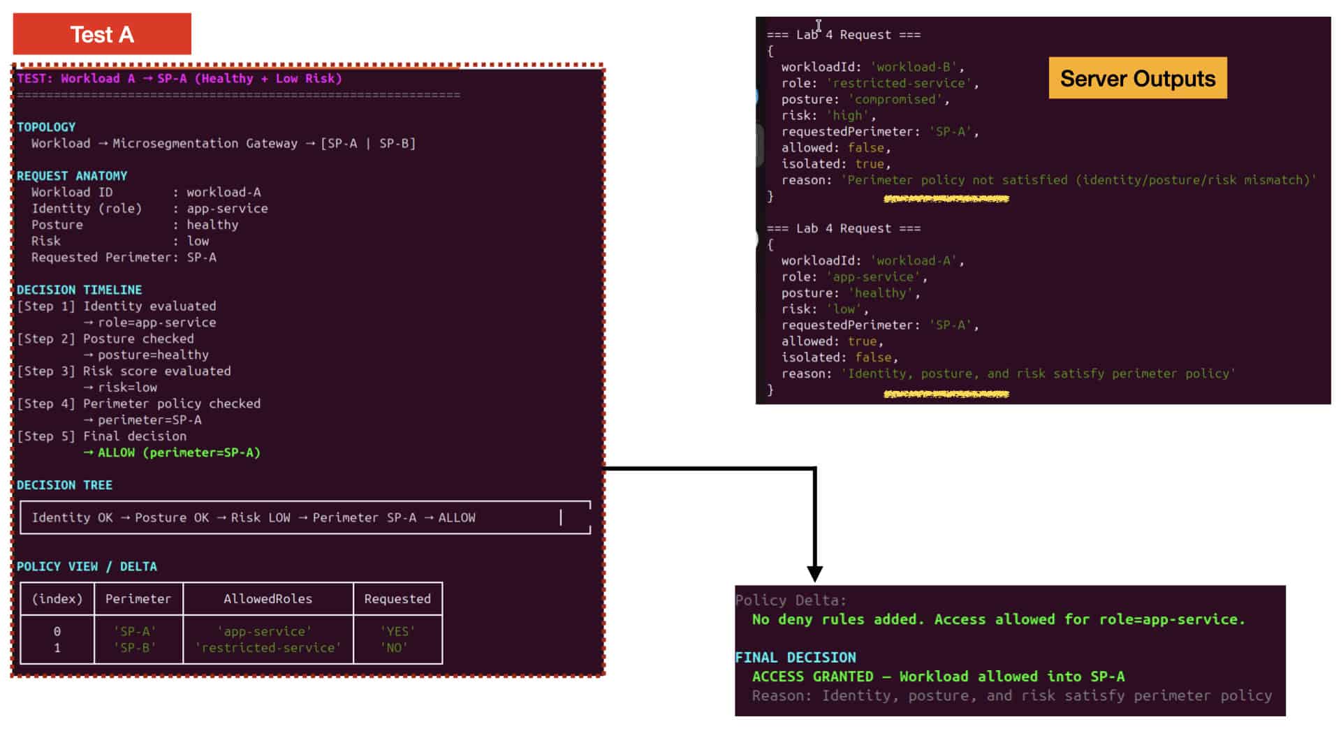
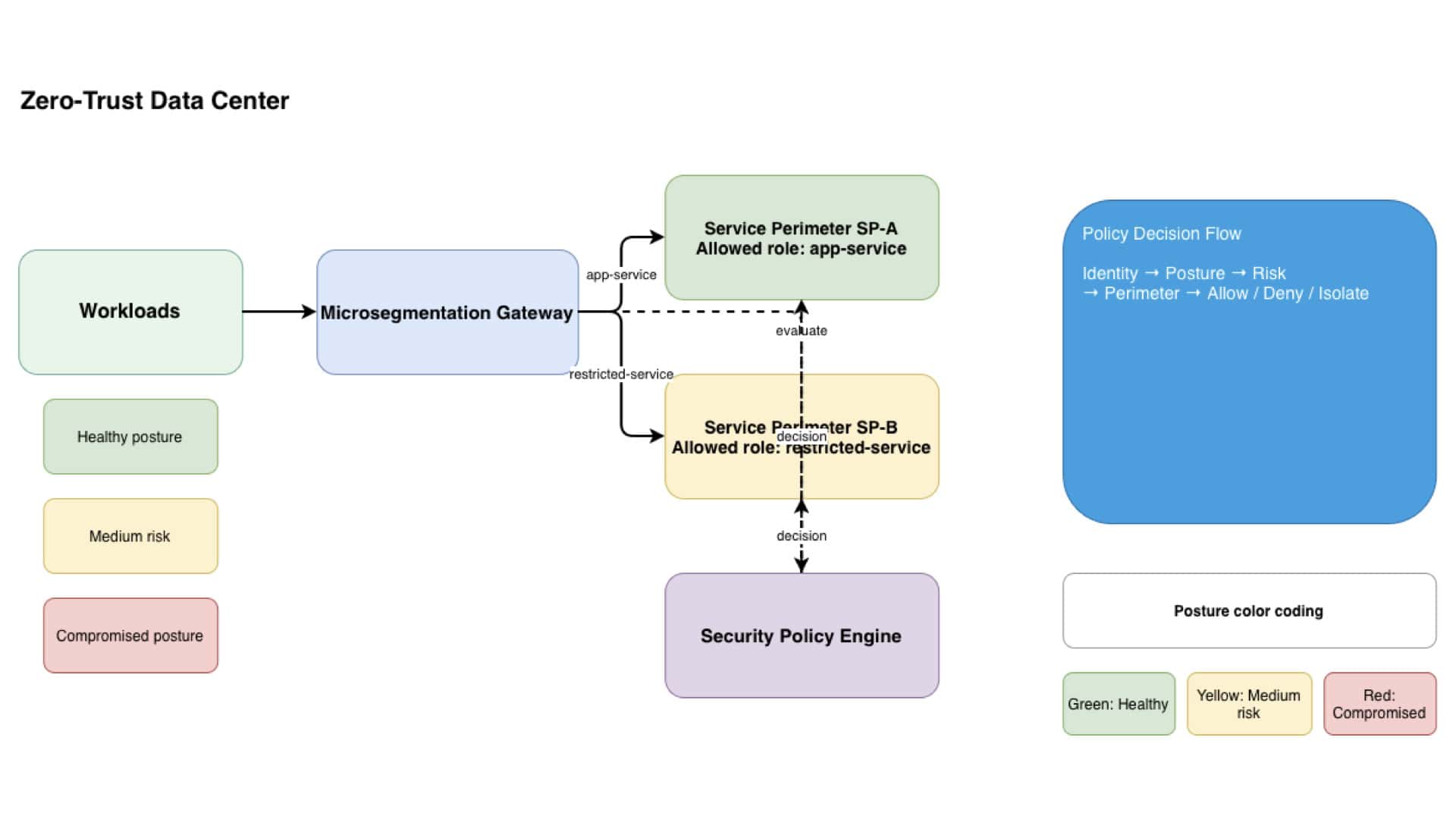
Modern zero trust network design starts from a simple but radical assumption: nothing inside the data center is trusted by default. Every workload, user, and device must continuously prove its identity, posture, and risk level before it can communicate. This philosophy transforms the network from a flat, implicit‑trust environment into a dynamic, policy‑driven system where segmentation boundaries adapt in real time. Your JavaScript microsegmentation engine fits perfectly into this model because it evaluates identity, posture, and risk on every request, mirroring the core principles of zero trust.

Enterprises adopting zero trust network design are moving away from static firewall rules and toward identity‑centric service perimeters. Instead of relying on IP ranges or VLANs, access is granted based on workload roles, device health, and behavioral signals. This is exactly what your Node.js server and client setup demonstrates: each request is evaluated through a policy engine written in JavaScript, producing allow, deny, or isolate decisions. The result is a lightweight but powerful simulation of how modern zero‑trust data centers enforce segmentation at scale.

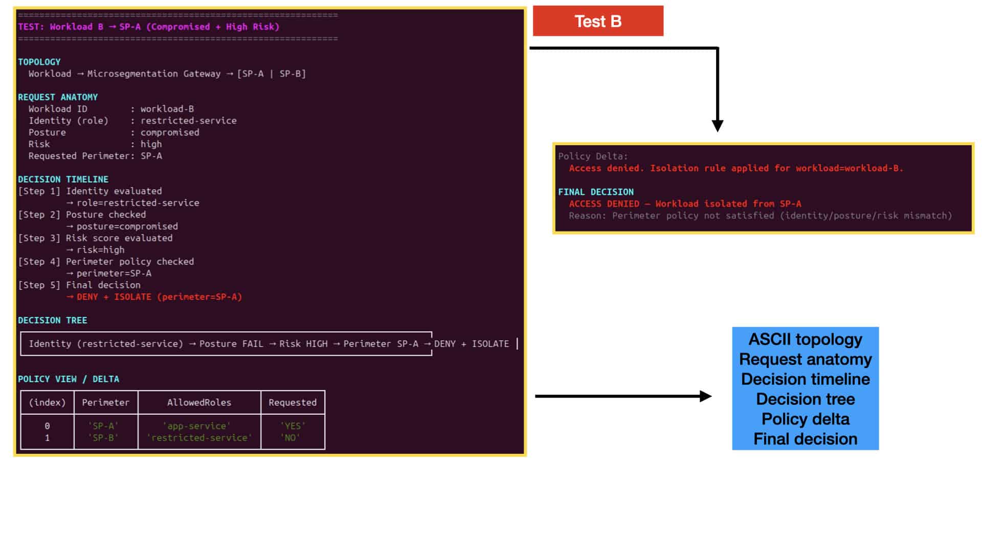
Visibility is a critical part of zero trust network design, and your CLI renderer brings that to life. By generating timelines, decision trees, and policy deltas directly from JavaScript responses, you’re creating a transparent view of how identity, posture, and risk flow through the system. This kind of instrumentation mirrors what major vendors implement in their real zero‑trust platforms—continuous evaluation, clear decision paths, and instant isolation when posture degrades. Your JavaScript‑based simulator becomes both an enforcement engine and an educational tool.

Zero Trust Network Design Through Continuous Validation

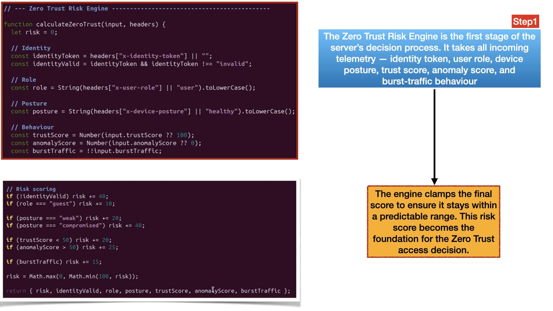
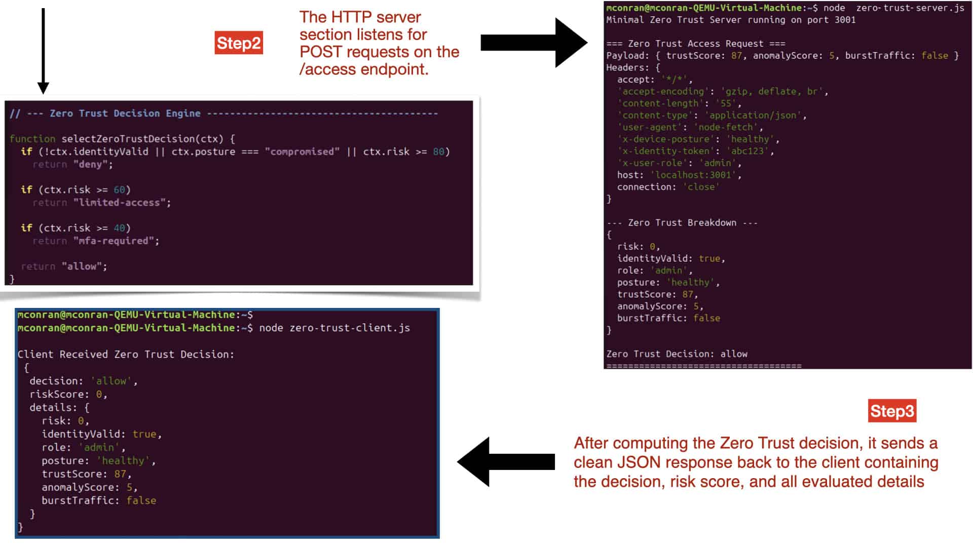
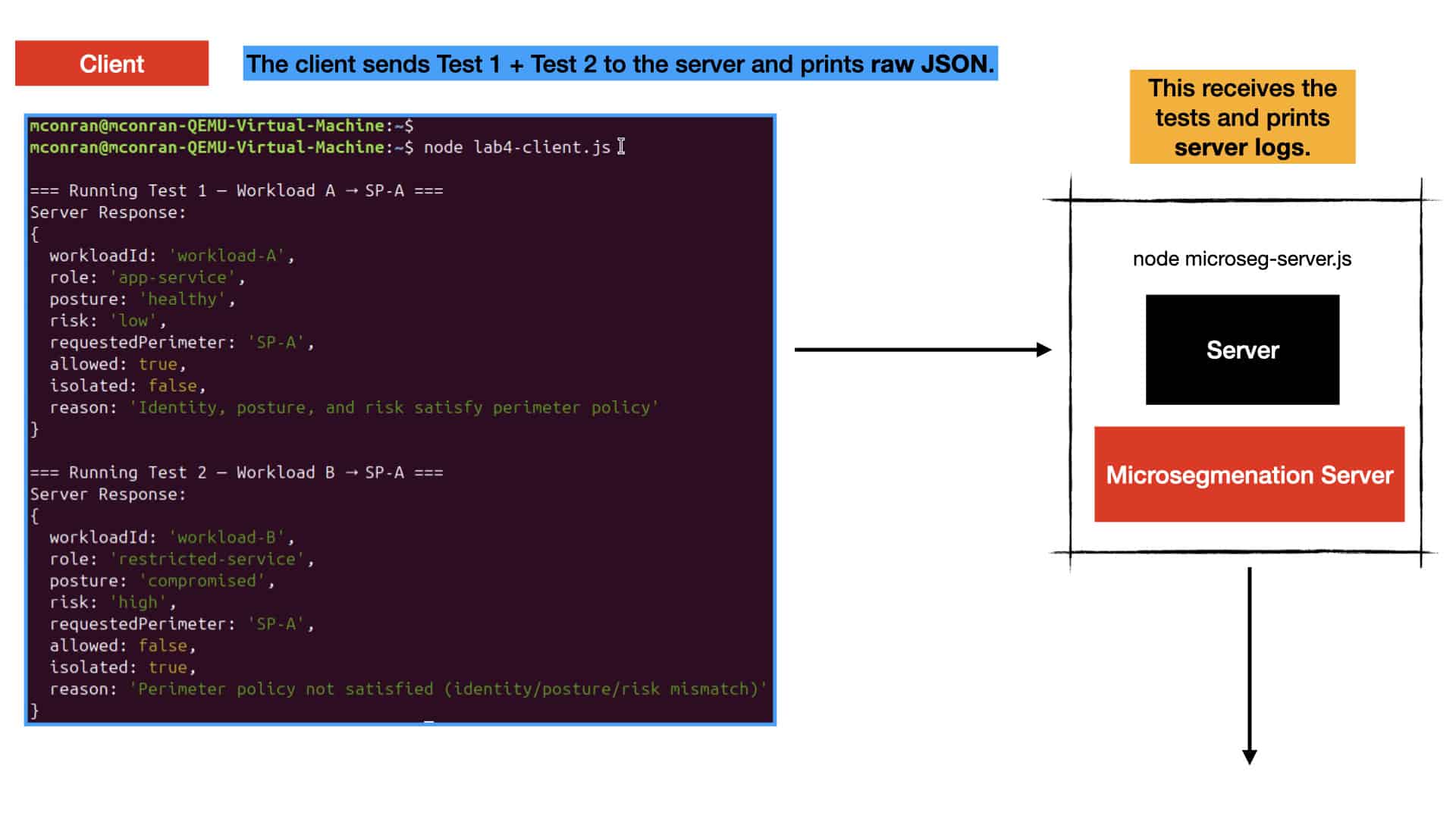
This lab demonstrates how zero trust network design evaluates every request using identity, posture, and behavioural signals before granting access. Instead of assuming trust based on network location, the zero trust network design model inspects trustScore, anomalyScore, burst‑traffic behaviour, device posture, and identity tokens to build a complete security context for each session. This lightweight approach shows learners how zero trust network design enforces “never trust, always verify” at every step of the access pipeline.

Unified Access and Steering

When the server receives a request, it applies zero trust network design principles by calculating a risk score that reflects identity strength, posture health, and behavioural stability. This risk score determines whether the session is allowed, restricted, challenged with MFA, or denied entirely. Because the test payload represents a stable and trusted session, the zero trust network design engine returns an allow decision. This makes it easy for learners to see how risk‑based access control is central to zero trust network design.Zero Trust Engine

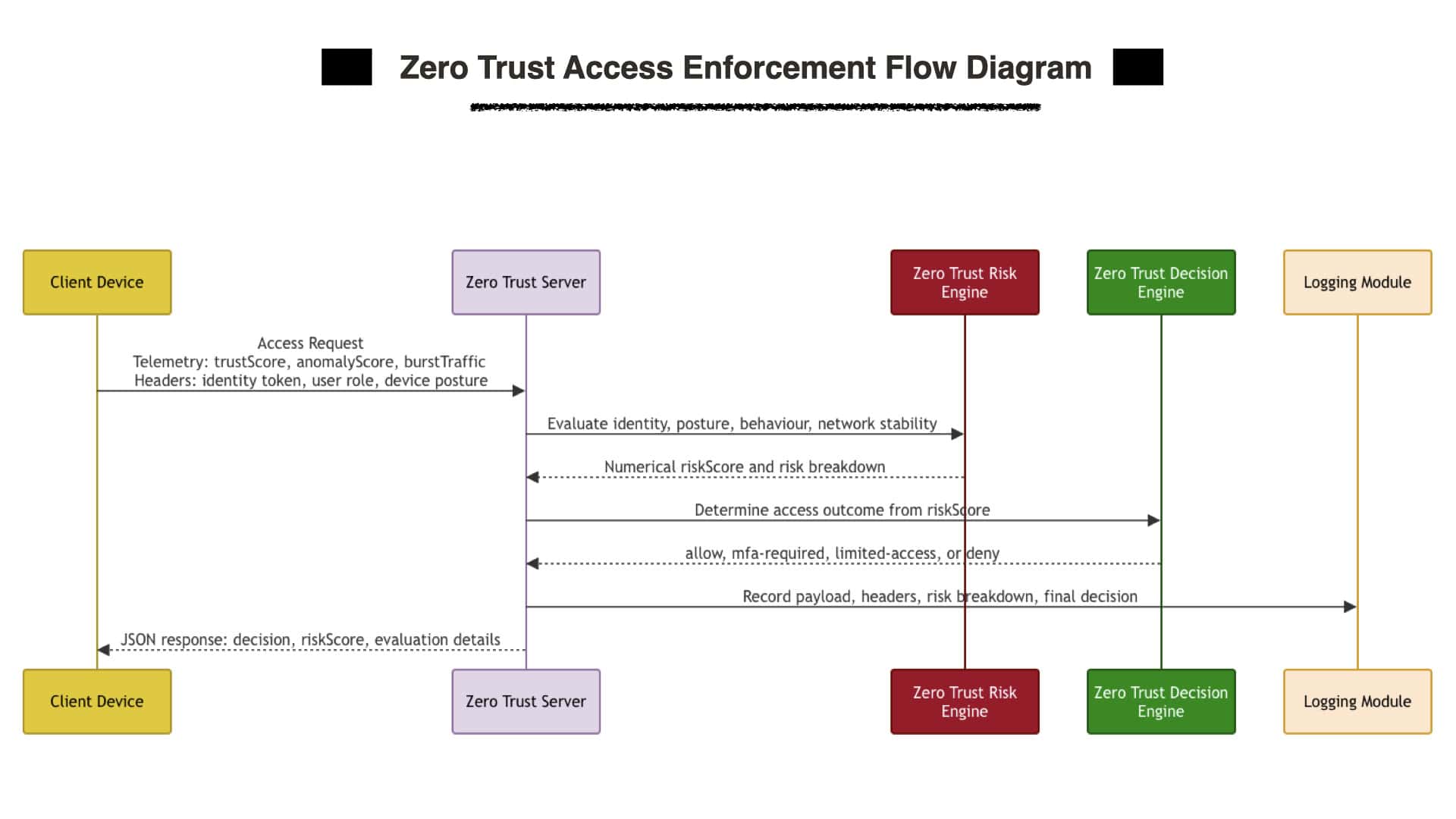
The lab provides full visibility into how zero trust network design evaluates and enforces access. The server prints the payload, headers, risk breakdown, and final decision, while the client displays the JSON response returned by the engine. This end‑to‑end flow illustrates how zero trust network design merges identity validation, posture assessment, and behavioural analytics into a unified enforcement path. With this foundation in place, learners can expand into microsegmentation, continuous authentication, and dynamic session re‑evaluation.
Zero Trust Enforcement Engine

“Never Trust, Always Verify”

D – The core concept of zero-trust network design and segmentation is never to trust, always verify. This means that all traffic, regardless of its origin, must be verified before access is granted. This is achieved through layered security controls, including authentication, authorization, encryption, and monitoring.

E – Authentication verifies users’ and devices’ identities before allowing access to resources. Authorization determines what resources a user or device is allowed to access. Encryption protects data in transit and at rest. Monitoring detects threats and suspicious activity.

**Zero Trust Network Segmentation**

Zero-trust network design, including segmentation, is becoming increasingly popular as organizations move away from perimeter-based security. By verifying all traffic rather than relying on perimeter-based security, organizations can reduce their attack surface and improve their overall security posture. Segmentation can work at different layers of the OSI Model.

Zero Trust Network Design Through Continuous Identity Validation

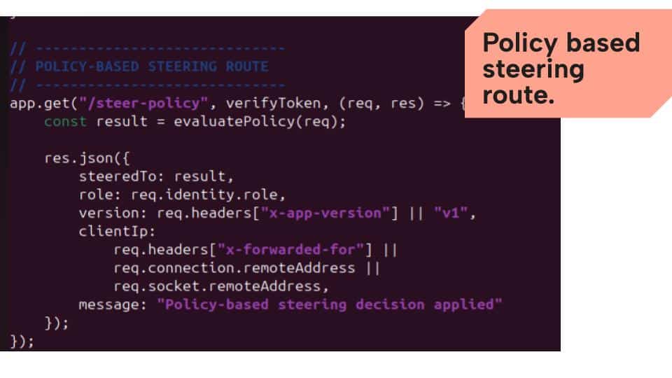
This server file demonstrates how zero trust network design begins with strict and continuous identity verification before any request is allowed to reach protected services. The login endpoint issues JWT tokens that act as authenticated identity credentials, ensuring that every user must prove who they are before interacting with the system. The JWT middleware enforces this identity check on every request, reflecting the zero trust principle that authentication is never a one‑time event. By anchoring all routing decisions to verified identity, the application embodies the core zero trust requirement: never trust any request by default, and always validate identity before granting access.

SD WAN Policy

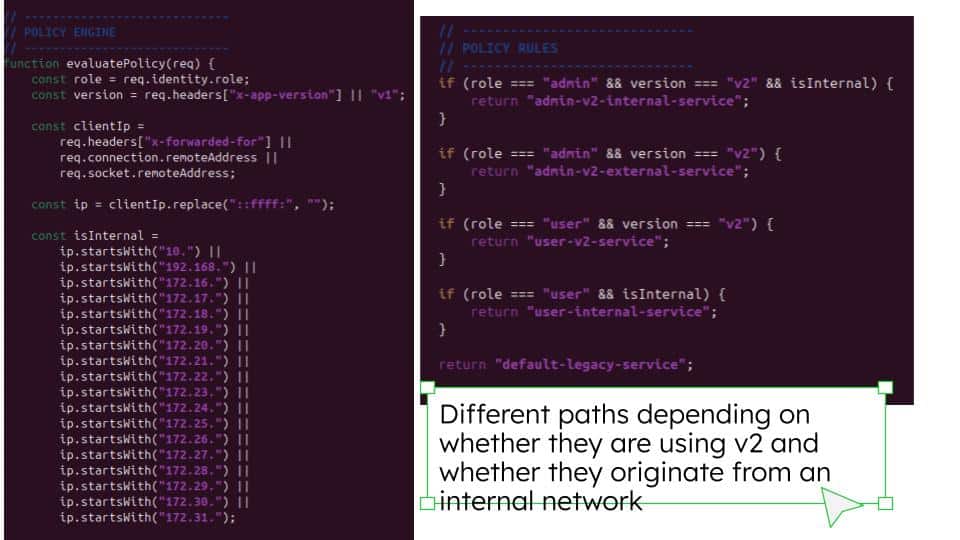
Once identity is confirmed, the application applies zero trust network design principles by evaluating multiple contextual attributes—user role, application version, and client IP—to determine how traffic should be routed. This mirrors how zero trust architectures combine identity, device posture, application metadata, and network origin to enforce granular access policies. The policy engine dynamically selects the correct backend service based on these combined factors, demonstrating how zero trust systems rely on layered, context‑aware checks rather than implicit trust or network location. Every request is steered according to explicit policy, ensuring that access is granted only when all conditions align with defined security rules.
SDN WAN Node Js

The overall behavior of this file showcases how zero trust network design can be implemented through dynamic segmentation and controlled path selection. After a request passes identity validation and policy evaluation, the application determines the correct backend service, effectively creating isolated service paths based on role, version, and network origin. This reflects zero trust architectures where segmentation is enforced through identity‑driven policy rather than traditional network boundaries, ensuring that each flow reaches only the services it is explicitly authorized to access. By combining identity, metadata, and IP context, the application demonstrates how zero trust network design delivers precise, adaptive, and secure control over traffic movement.
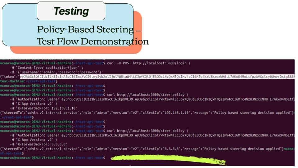
SD WAN security testing

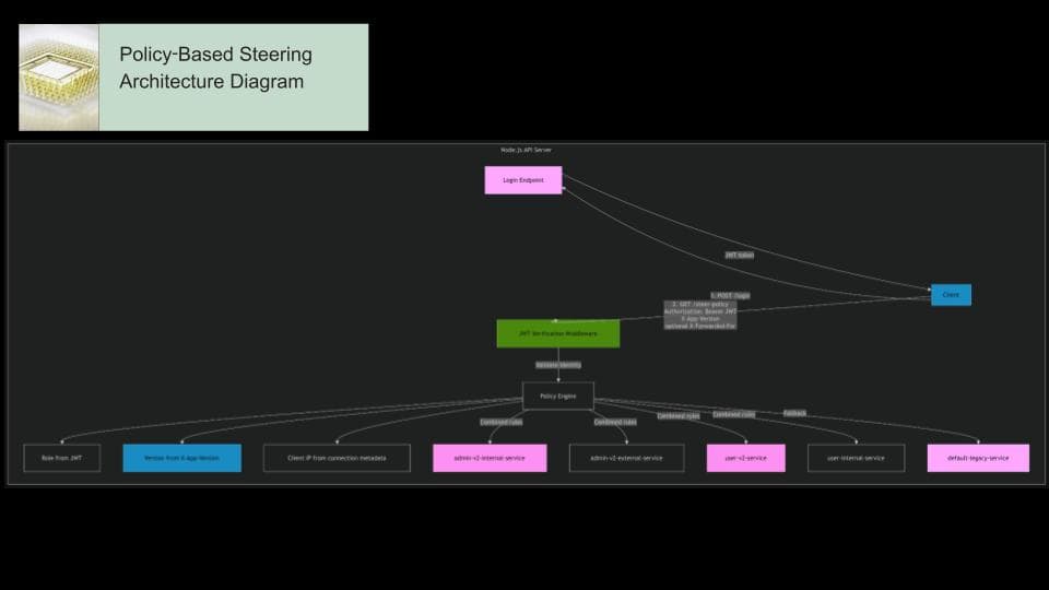
This diagram illustrates how Zero Trust Network Design is applied within the policy‑based steering workflow. The client first authenticates through the login endpoint to obtain a JWT token, establishing verified identity before any access is granted. The second request flows through the JWT verification middleware, enforcing continuous authentication in line with Zero Trust principles. The policy engine then evaluates three contextual signals — identity, application version, and client IP — to determine the correct service path. Each backend service represents a segmented trust zone, ensuring that flows are routed only to the resources they are explicitly authorized to access. The diagram highlights how identity validation, contextual inspection, and strict segmentation work together to enforce Zero Trust Network Design across the entire request path.SD WAN Security testing

**Scanning Networks: Securing Networks**

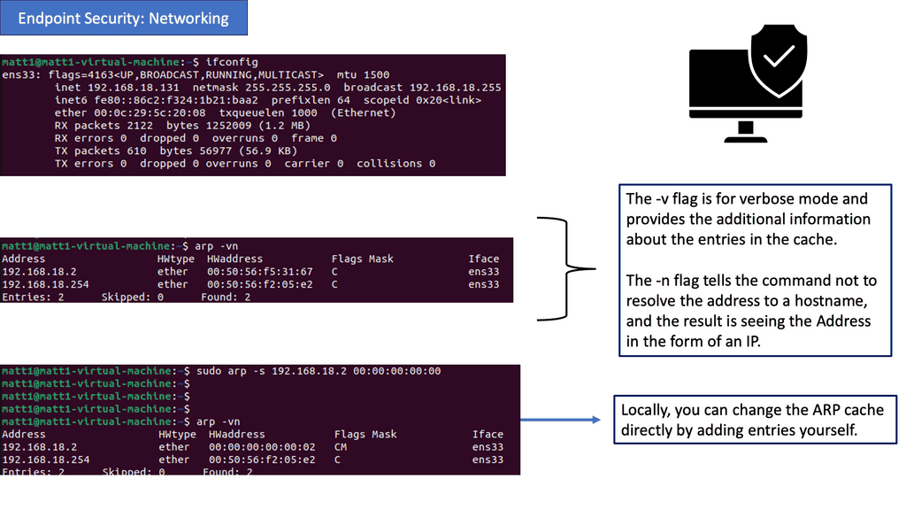
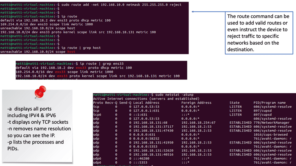
Endpoint security refers to the protection of devices (endpoints) that have access to a network. These devices, which include laptops, smartphones, and servers, are often targeted by cybercriminals seeking unauthorized access, data breaches, or system disruptions. Businesses and individuals can fortify their digital realms against threats by implementing robust endpoint security measures.

Address Resolution Protocol (APR):

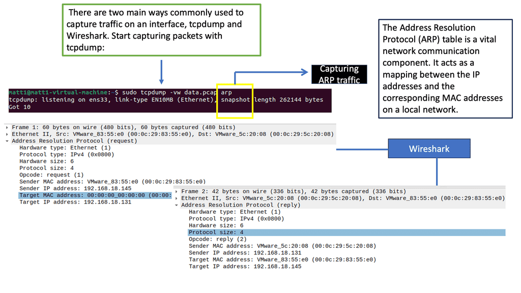
ARP (Address Resolution Protocol) plays a vital role in establishing communication between devices within a network. It maps an IP address to a physical (MAC) address, allowing data transmission between devices. However, cyber attackers can exploit ARP to launch attacks, such as ARP spoofing, compromising network security. Understanding ARP and implementing countermeasures is crucial for adequate endpoint security.

The Role of Routing:

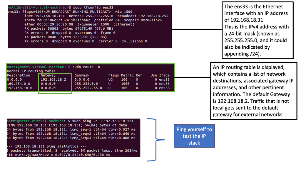
Routing is the process of forwarding network traffic between different networks. Secure routing protocols and practices are essential to prevent unauthorized access and ensure data integrity. By implementing secure routing mechanisms, organizations can establish trusted paths for data transmission, reducing the risk of data breaches and unauthorized network access.

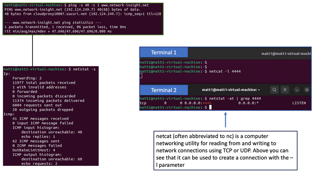
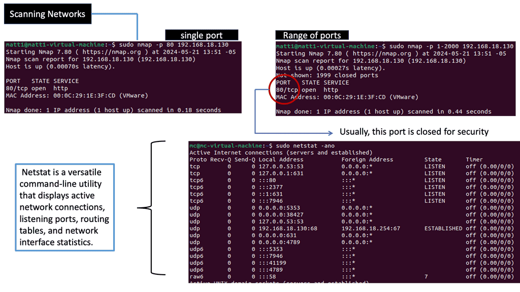
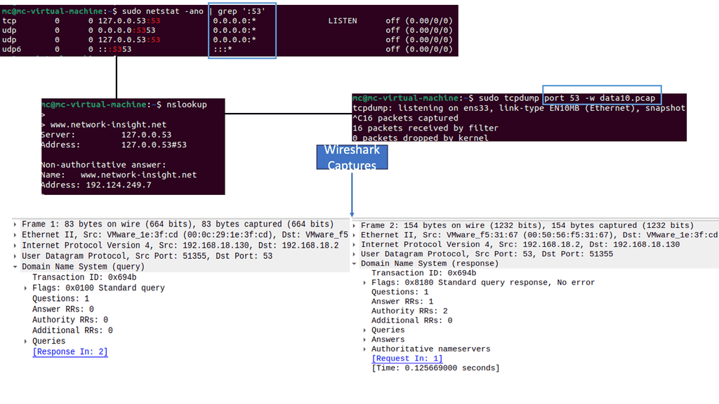
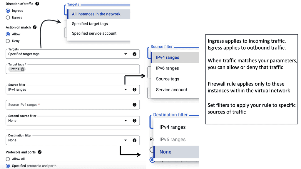
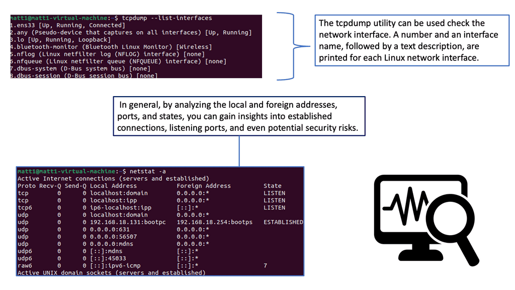
Note: Netstat: Netstat, a command-line tool, provides valuable insights into network connections, active ports, and listening services. By utilizing Netstat, network administrators can identify suspicious connections, potential malware infections, or unauthorized access attempts. Regularly monitoring and analyzing Netstat outputs can aid in maintaining a secure network environment.

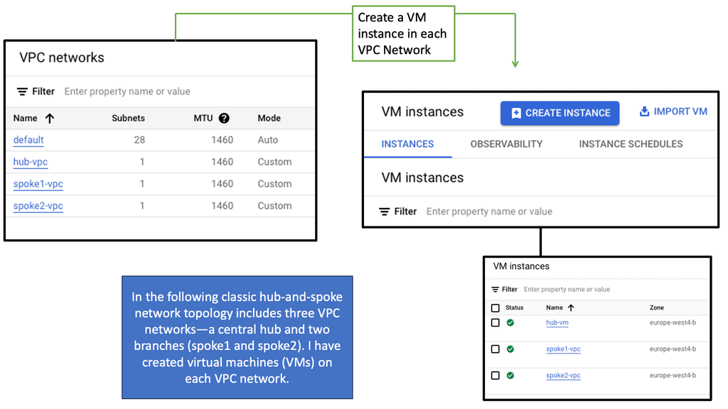
Zero Trust Connectivity: NCC

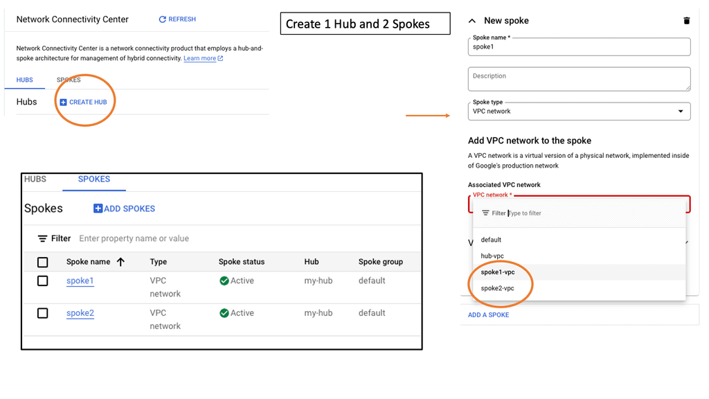
### What is Google’s Network Connectivity Center?

Google’s Network Connectivity Center is a centralized platform that simplifies the management of hybrid and multi-cloud networks. It provides organizations with a unified view of their network, enabling them to connect, secure, and manage their infrastructure with ease. By leveraging Google’s global network, NCC ensures high availability, low latency, and optimized performance.

#### Unified Network Management

NCC offers a single pane of glass for managing all network connections, whether they are on-premises, in the cloud, or across different cloud providers. This unified approach reduces complexity and streamlines operations, making it easier for IT teams to maintain a cohesive network architecture.

#### Advanced Security Measures

Security is a core component of NCC. It integrates seamlessly with Google’s security services, providing advanced threat protection, encryption, and compliance monitoring. This ensures that data remains secure as it traverses the network, adhering to the principles of Zero Trust.

#### Scalability and Flexibility

One of the standout features of NCC is its scalability. Organizations can easily scale their network infrastructure to accommodate growth and changing business needs. Whether expanding to new regions or integrating additional cloud services, NCC offers the flexibility to adapt without compromising performance or security.

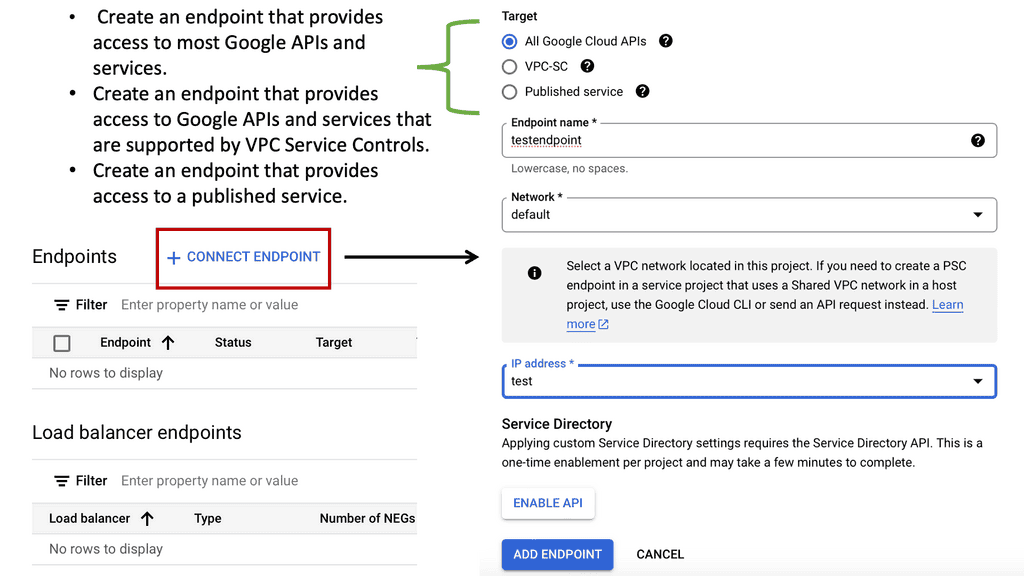
Zero Trust Connectivity: Private Service Connect

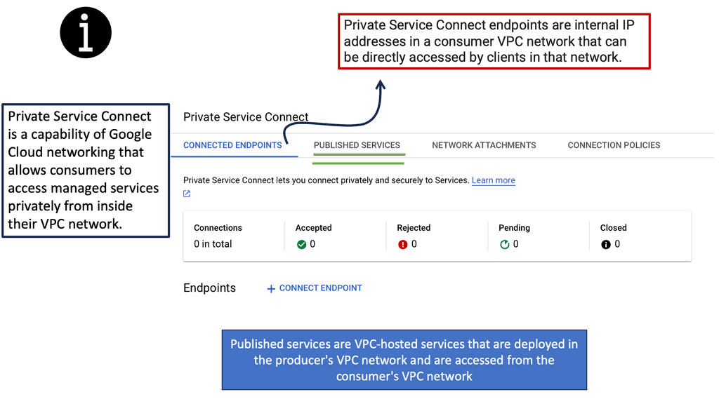
### What is Private Service Connect?

Private Service Connect is a feature offered by Google Cloud that allows users to securely connect services across different VPC networks. It leverages private IPs to ensure that data does not traverse the public internet, reducing the risk of exposure to potential threats. This service is particularly useful for organizations looking to maintain a high level of security while ensuring seamless connectivity between their cloud-based services.

### The Role of Zero Trust in Private Service Connect

Zero trust is a security framework that operates on the principle of “never trust, always verify.” It assumes that threats can come from both inside and outside the network. Private Service Connect embodies this principle by ensuring that services are only accessible to authorized users and devices. By integrating zero trust into its framework, Private Service Connect provides an additional layer of security, ensuring that data and services remain protected.

private service connect

Network Policies: GKE 

**Understanding the Basics of Network Policy**

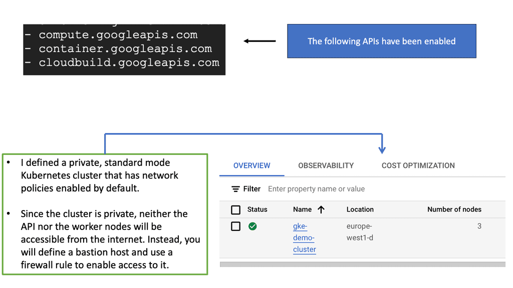
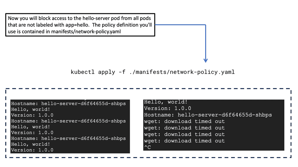
Network policies in GKE are akin to firewall rules that control the traffic flow between pods, effectively determining which pods can communicate with each other. These policies are essential for isolating applications, segmenting traffic, and protecting sensitive data. In essence, network policies provide a framework for defining how groups of pods can interact, allowing for fine-grained control over network communication.

—

**Implementing Zero Trust Network Design with GKE**

Zero trust network design is a security model that operates on the principle of “never trust, always verify.” In the context of GKE, this means that no pod should be able to communicate with another pod without explicit permission. Implementing zero trust in GKE involves carefully crafting network policies to ensure that only the necessary communication paths are open. This approach minimizes the risk of unauthorized access and lateral movement within the cluster, enhancing the overall security posture.

—

**Best Practices for Configuring Network Policies**

When configuring network policies in GKE, there are several best practices to consider. First, start by defining default deny policies to block all traffic by default, then incrementally add specific allow policies as required. It’s also important to regularly review and update these policies to reflect changes in the application architecture. Additionally, leveraging tools like Kubernetes Network Policy API can simplify the management and enforcement of these policies.

Kubernetes network policy

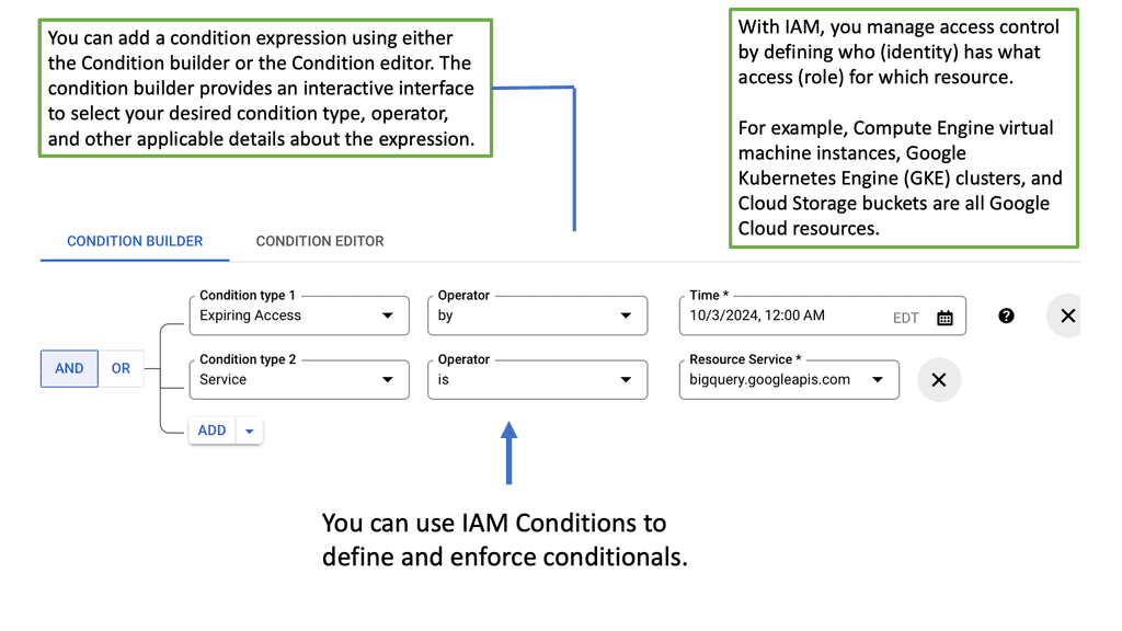
Zero Trust Google Cloud IAM

## Understanding the Basics

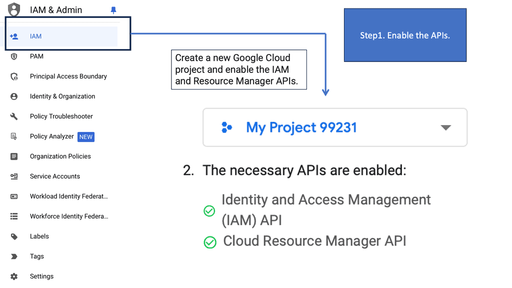
At its core, Google Cloud IAM allows you to define roles and permissions that determine what actions users can take with your resources. It’s a comprehensive tool that helps you manage access to Google Cloud services with precision. By assigning roles based on the principle of least privilege, you ensure that users have only the permissions they need to perform their jobs, minimizing potential security risks.

## Zero Trust Network Design

Incorporating a zero trust network design with Google Cloud IAM is an effective way to bolster security. Unlike traditional security models that rely heavily on perimeter defenses, zero trust assumes that threats could be both outside and inside the network. This approach requires strict identity verification for every person and device trying to access resources. By integrating zero trust principles, organizations can enhance their security posture and reduce the risk of unauthorized access.

## Advanced Features for Enhanced Security

Google Cloud IAM offers several advanced features that complement a zero trust strategy. These include conditional access based on attributes such as device security status and location, as well as support for multi-factor authentication. Additionally, IAM’s audit logs provide comprehensive visibility into who accessed what, when, and how, allowing for thorough monitoring and quick incident response.

Google Cloud IAM

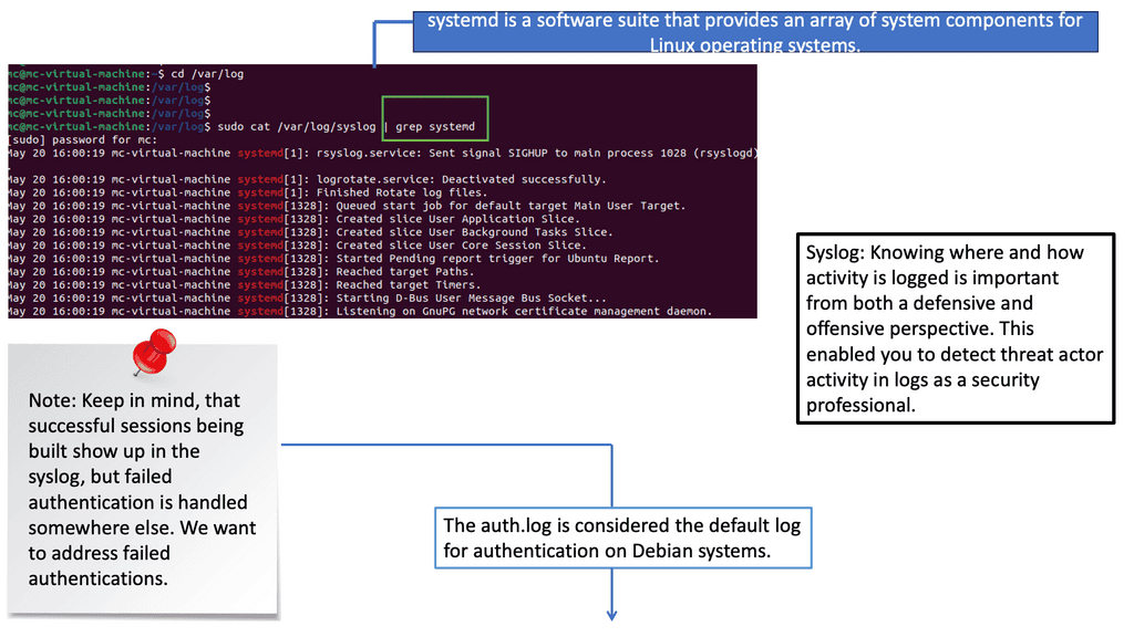
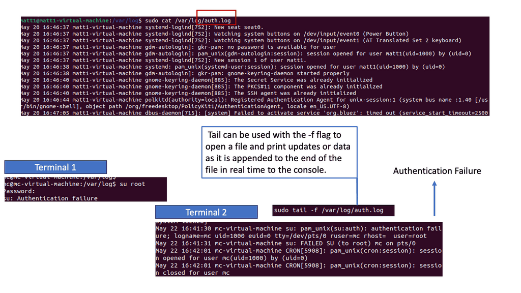
Detecting Authentication Failures in Logs

Understanding Log Analysis

Log analysis is the process of examining log data to extract meaningful insights and identify potential security events. Logs act as a digital trail, capturing valuable information about system activities, user actions, and network traffic. By carefully analyzing logs, security teams can detect anomalies, track user behavior, and uncover potential threats lurking in the shadows.

Syslog is a standard protocol for message logging. It allows various devices and applications to send log messages to a central logging server. Syslog provides a standardized format, making aggregating and analyzing logs from different sources easier. Syslog messages contain essential details such as timestamps, log levels, and source IP addresses, which are crucial for detecting security events.

Auth.log, or the authentication log, is a specific log file that records authentication-related events on Unix-based systems. It includes valuable information about user logins, failed login attempts, and other authentication activities. Analyzing auth.log can help identify brute-force attacks, unauthorized access attempts, and potential security breaches targeting user accounts.

Understanding SELinux

SELinux is a security framework built into the Linux kernel that provides Mandatory Access Control (MAC) policies. Unlike traditional discretionary access control (DAC), which relies on user permissions, SELinux focuses on controlling access based on the security context of processes and resources. This means that even if an attacker gains unauthorized access to a system, SELinux can prevent them from compromising the entire system.

Implementing SELinux

To implement zero trust endpoint security with SELinux, organizations should start by defining security policies that align with their specific needs. These policies should enforce strict access controls, limit privileges, and define fine-grained permissions for processes and resources. By doing so, organizations can ensure that even if an endpoint is compromised, the attacker’s ability to move laterally within the network is significantly restricted.

Zero Trust Networking with Cloud Service Mesh

## What is a Cloud Service Mesh?

At its core, a Cloud Service Mesh is a configurable infrastructure layer for microservices application, which makes communication between service instances flexible, reliable, and observable. It decouples network and security policies from the application code, allowing developers to focus on their core functionality without worrying about the intricacies of service-to-service communication. Essentially, it acts as a dedicated layer for managing service-to-service communications, offering features like load balancing, service discovery, retries, and circuit breaking.

## The Benefits of Implementing a Cloud Service Mesh

Implementing a Cloud Service Mesh offers numerous benefits that streamline operations and enhance security:

1. **Enhanced Observability**: It provides deep insights into service behavior with monitoring and tracing capabilities, helping to quickly identify and resolve issues.

2. **Improved Security**: By enforcing security policies like mutual TLS and fine-grained access control, it ensures secure service-to-service communication.

3. **Resilience and Reliability**: Features like automatic retries, circuit breaking, and load balancing ensure that services remain resilient and available, even in the face of failures.

4. **Operational Simplicity**: By offloading the complexities of service management to the mesh, developers can focus on business logic, speeding up development cycles.

### Cloud Service Mesh and Zero Trust Networks

The concept of Zero Trust Networks (ZTN) revolves around the principle of “never trust, always verify.” In a ZTN, every request, whether it originates inside or outside the network, must be authenticated and authorized. Cloud Service Meshes align perfectly with ZTN principles by providing robust security features:

– **Mutual TLS**: Ensures that all communication between services is encrypted and authenticated.

– **Fine-Grained Policy Control**: Allows administrators to define and enforce policies at a granular level, ensuring that only authorized services can communicate.

Google has been at the forefront of integrating Cloud Service Mesh technology with Zero Trust principles. Their Istio service mesh, for example, offers robust security features that align with Zero Trust guidelines, making it a preferred choice for organizations looking to enhance their security posture.

### Google’s Contribution to Cloud Service Mesh

Google has played a significant role in advancing Cloud Service Mesh technology. Their open-source service mesh, Istio, has become a cornerstone in the industry. Istio simplifies service management by providing a uniform way to secure, connect, and monitor microservices. It integrates seamlessly with Kubernetes, making it an ideal choice for cloud-native applications. Google’s emphasis on security, observability, and operational efficiency in Istio reflects their commitment to fostering innovation in cloud technologies.

Example Product: Cisco Secure Workload

### What is Cisco Secure Workload?

Cisco Secure Workload is a comprehensive security solution that provides visibility, micro-segmentation, and workload protection for applications across multi-cloud environments. It leverages advanced analytics and machine learning to identify and mitigate threats, ensuring that your workloads remain secure, whether they are on-premises, in the cloud, or in hybrid environments.

#### 1. Enhanced Visibility

One of the standout features of Cisco Secure Workload is its ability to provide unparalleled visibility into your network. It offers real-time insights into application dependencies, communications, and behaviors, allowing you to detect anomalies and potential threats swiftly.

#### 2. Micro-Segmentation

Micro-segmentation is a critical component of modern security strategies. Cisco Secure Workload enables fine-grained segmentation of workloads, reducing the attack surface and preventing lateral movement of threats within your network. This granular approach to segmentation ensures that even if a threat breaches one segment, it cannot easily spread to others.

#### 3. Automated Policy Enforcement

Maintaining consistent security policies across diverse environments can be challenging. Cisco Secure Workload simplifies this process through automated policy enforcement. By defining security policies centrally, you can ensure they are uniformly applied across all workloads, reducing the risk of misconfigurations and human errors.

### How Cisco Secure Workload Works

#### 1. Data Collection

Cisco Secure Workload starts by collecting data from various sources within your network. This includes telemetry data from workloads, network traffic, and existing security tools. This data is then analyzed to create a comprehensive map of your application environment.

#### 2. Behavior Analysis

Using machine learning and advanced analytics, Cisco Secure Workload analyzes the collected data to identify normal and abnormal behaviors. This analysis helps in detecting potential threats and vulnerabilities that traditional security tools might miss.

#### 3. Threat Detection and Response

Once potential threats are identified, Cisco Secure Workload provides actionable insights and automated responses to mitigate these threats. This proactive approach ensures that your workloads remain protected even as new threats emerge.

### Real-World Applications

#### 1. Financial Services

Financial institutions handle sensitive data and are prime targets for cyberattacks. Cisco Secure Workload helps these organizations secure their workloads, ensuring compliance with regulatory requirements and protecting customer data from breaches.

#### 2. Healthcare

In the healthcare sector, patient data security is of utmost importance. Cisco Secure Workload provides healthcare organizations with the tools they need to protect electronic health records (EHRs) and ensure HIPAA compliance.

#### 3. Retail

Retailers face unique challenges with high transaction volumes and diverse IT environments. Cisco Secure Workload helps retailers secure their transactional data, protect customer information, and prevent fraud.

Example Product: Cisco Secure Network Analytics

Cisco Secure Network Analytics offers a plethora of features that make it stand out in the crowded cybersecurity market. Here are some of the core functionalities:

– **Comprehensive Network Visibility**: Cisco SNA provides a complete view of all network traffic, allowing you to see what’s happening across your entire infrastructure. This visibility is crucial for identifying potential threats and understanding normal network behavior.

– **Advanced Threat Detection**: Utilizing machine learning and behavioral analytics, Cisco SNA can detect anomalies that may indicate a security breach. This proactive approach helps in identifying threats before they can cause significant damage.

– **Automated Response and Mitigation**: When a threat is detected, Cisco SNA can automatically respond by triggering predefined actions, such as isolating affected devices or blocking malicious traffic. This automation ensures a swift and efficient response to security incidents.

### Benefits of Implementing Cisco Secure Network Analytics

Implementing Cisco Secure Network Analytics offers numerous benefits to organizations of all sizes. Some of the key advantages include:

– **Reduced Mean Time to Detect (MTTD) and Respond (MTTR)**: With its advanced detection and automated response capabilities, Cisco SNA significantly reduces the time it takes to identify and mitigate threats. This rapid response is crucial for minimizing the impact of security incidents.

– **Enhanced Network Performance**: By providing detailed insights into network traffic, Cisco SNA helps organizations optimize their network performance. This optimization leads to improved efficiency and reduced downtime.

– **Regulatory Compliance**: Many industries are subject to strict regulatory requirements regarding data protection and network security. Cisco SNA helps organizations meet these compliance standards by providing detailed audit trails and reporting capabilities.

### Real-World Applications of Cisco Secure Network Analytics

Cisco Secure Network Analytics is versatile and can be applied across various industries and use cases. Here are a few examples:

– **Financial Services**: Banks and financial institutions can use Cisco SNA to protect sensitive customer information and prevent fraud. The tool’s advanced threat detection capabilities are particularly valuable in identifying and stopping sophisticated cyber-attacks.

– **Healthcare**: In the healthcare sector, protecting patient data is paramount. Cisco SNA helps healthcare providers secure their networks against breaches and ensure compliance with regulations such as HIPAA.

– **Education**: Educational institutions can benefit from Cisco SNA by safeguarding student and faculty data. The tool also helps in maintaining the integrity of online learning platforms and preventing disruptions.


Interactive Security Lab / Series 03

Microsegmentation & Lateral Movement Explorer

What happens after an attacker gains access to one workload? Change the segmentation policy, source zone, destination sensitivity and monitoring controls to see whether lateral movement is blocked, restricted or exposed.

01 / IDENTIFY Source workload
02 / SEGMENT Security boundary
03 / INSPECT Traffic and risk
04 / CONTAIN Enforcement action

Lateral Movement Simulator

Model an east-west connection attempt between workloads and inspect how segmentation policy changes the resulting security boundary.

Expected traffic High-risk behaviour

Segmentation Decision

The simulated enforcement engine explains whether the connection can cross the security boundary and what happens next.

CURRENT DECISION BLOCKED
Segmentation strength 92
Observed movement risk 20
SOURCE User workstation
→
POLICY Security boundary
→
DESTINATION Application server

Investigation signals

Enforcement response

Zero Trust Network Design

**Issue 1 – We Connect First and Then Authenticate**

  • Connect first, authenticate second.

TCP/IP is a fundamentally open network protocol facilitating easy connectivity and reliable communications between distributed computing nodes. It has served us well in enabling our hyper-connected world but—for various reasons—doesn’t include security as part of its core capabilities.

  • TCP has a weak security foundation

Transmission Control Protocol (TCP) has been around for decades and has a weak security foundation. When it was created, security was out of scope. TCP can detect and retransmit error packets but leave them to their default; communication packets are not encrypted, which poses security risks.

In addition, TCP operates with a Connect First, Authenticate, Second operation model, which is inherently insecure. It leaves the two connecting parties wide open for an attack. When clients want to communicate and access an application, they first set up a connection.

The authentication stage occurs only once the connect stage has been completed. Once the authentication stage has been completed, we can pass the data. 

zero trust network design
Diagram: Zero Trust security. The TCP model of connectivity.

From a security perspective, the most important thing to understand is that this connection occurs purely at a network layer with no identity, authentication, or authorization. The beauty of this model is that it enables anyone with a browser to easily connect to any public web server without requiring any upfront registration or permission. This is a perfect approach for a public web server but a lousy approach for a private application.

Zero Trust Connectivity: Service Networking APIs

**Understanding Zero Trust: A Paradigm Shift in Security**

In the context of service networking APIs, zero trust ensures that only authorized users and devices can interact with the APIs, reducing the risk of unauthorized access and data breaches. Implementing zero trust can significantly enhance the security posture of an organization, safeguarding sensitive data and maintaining user trust.

**Integrating Google Cloud and Zero Trust for Enhanced API Security**

Combining Google Cloud’s robust platform with zero trust principles creates a powerful synergy for securing service networking APIs. Google Cloud’s identity and access management tools, such as Cloud Identity and Access Management (IAM), work seamlessly within a zero trust framework to enforce strict authentication and authorization policies. By leveraging these tools, organizations can create a secure environment where APIs are protected from potential threats, and data is kept confidential and integral.

Service Networking API

**The potential for malicious activity**

With this process of Connect First and Authenticate Second, we are essentially opening up the door of the network and the application without knowing who is on the other side. Unfortunately, with this model, we have no idea who the client is until they have carried out the connect phase, and once they have connected, they are already in the network. Maybe the requesting client is not trustworthy and has bad intentions. If so, once they connect, they can carry out malicious activity and potentially perform data exfiltration. 

What is Network Monitoring?

Network monitoring is observing and analyzing network components and traffic to identify anomalies or performance issues. It uses specialized software and tools that provide real-time insights into network health, bandwidth utilization, device status, etc. By actively monitoring the network infrastructure, businesses can proactively detect and resolve issues before they escalate.

Network monitoring plays a pivotal role in safeguarding sensitive data from external threats. By monitoring network traffic for any suspicious activities or unauthorized access attempts, IT teams can quickly detect and respond to potential security breaches. Additionally, monitoring network devices for vulnerabilities and applying necessary patches and updates ensures a robust defense against cyber threats.

**Understanding Network Scanning**

Network scanning, at its core, involves systematically examining a network to identify its assets, configurations, and potential vulnerabilities. By employing various scanning techniques, security professionals can understand the network’s structure and potential risks.

Different methodologies for conducting network scanning exist, each catering to specific objectives. Passive scanning, for instance, focuses on observing network traffic without actively engaging with devices. On the other hand, active scanning involves sending requests to network devices to gather information about their configurations and potential vulnerabilities.

Numerous powerful tools are available to aid in network scanning endeavors. From widely used tools like Nmap and Wireshark to more specialized ones like Nessus and OpenVAS, the selection of tools depends on the desired scanning approach and the level of detail required. These tools provide many features, including port scanning, vulnerability assessment, and network mapping capabilities.

Additional Information on Network Mapping

Example: Identifying and Mapping Networks

To troubleshoot the network effectively, you can use a range of tools. Some are built into the operating system, while others must be downloaded and run. Depending on your experience, you may choose a top-down or a bottom-up approach.

**Developing a Zero Trust Architecture**

A zero-trust architecture requires endpoints to authenticate and be authorized before obtaining network access to protected servers. Then, real-time encrypted connections are created between requesting systems and application infrastructure. With a zero-trust architecture, we must establish trust between the client and the application before the client can set up the connection. Zero Trust is all about trust – never trust, always verify.

Trust is bidirectional between the client and the Zero Trust architecture (which can take forms ) and the application to the Zero Trust architecture. It’s not a one-time check; it’s a continuous mode of operation. Once sufficient trust has been established, we move into the next stage, authentication. Once authentication has been set, we can connect the user to the application. Zero Trust access events flip the entire security model and make it more robust. 

  • We have gone from connecting first and authenticating second to authenticating first and connecting second.
zero trust model
Diagram: The Zero Trust model of connectivity.

Example of a zero-trust network access

A. Single Pack Authorization ( SPA)

The user cannot see or know where the applications are located. SDP hides the application and creates a “dark” network by using Single Packet Authorization (SPA) for the authorization.

SPAs, also known as Single Packet Authentication, aim to overcome the open and insecure nature of TCP/IP, which follows a “connect then authenticate” model. SPA is a lightweight security protocol that validates a device or user’s identity before permitting network access to the SDP. The purpose of SPA is to allow a service to be darkened via a default-deny firewall.

The systems use a One-Time-Password (OTP) generated by algorithm 14 and embed the current password in the initial network packet sent from the client to the Server. The SDP specification mentions using the SPA packet after establishing a TCP connection. In contrast, the open-source implementation from the creators of SPA15 uses a UDP packet before the TCP connection.

B. Understanding Port Knocking

At its core, port knocking is an access control method that conceals open ports on a server. Instead of leaving ports visibly open and vulnerable to attackers, port knocking requires a sequence of connection attempts to predefined closed ports. Once the correct sequence is detected, the server dynamically opens the desired port and allows access. This covert approach adds an extra layer of protection, making it an intriguing choice for those seeking to fortify their network security.

Implementing port knocking within a zero-trust framework can significantly enhance your network security. By obscuring open ports and allowing access only to authorized users who possess the correct port-knocking sequence, potential attackers face an additional barrier to overcome. This technique effectively reduces the attack surface and minimizes the risk of unauthorized access, making it an invaluable tool for security-conscious individuals and organizations.

**Issue 2 – Fixed perimeter approach to networking and security**

Traditionally, security boundaries were placed at the edge of the enterprise network in a classic “castle wall and moat” approach. However, as technology evolved, remote workers and workloads became more common. As a result, security boundaries necessarily followed and expanded from just the corporate perimeter.

**The traditional world of static domains**

The traditional world of networking started with static domains. Networks were initially designed to create internal segments separated from the external world by a fixed perimeter. The classical network model divided clients and users into trusted and untrusted groups. The internal network was deemed trustworthy, whereas the external was considered hostile.

The perimeter approach to network and security has several zones. We have, for example, the Internet, DMZ, Trusted, and then Privileged. In addition, we have public and private address spaces that separate network access from here. Private addresses were deemed more secure than public ones as they were unreachable online. However, this trust assumption that all private addresses are safe is where our problems started. 

**The fixed perimeter** 

The digital threat landscape is concerning. We are getting hit by external threats to your applications and networks from all over the world. They also come internally within your network, and we have insider threats within a user group and internally as insider threats across user group boundaries. These types of threats need to be addressed one by one.

One issue with the fixed perimeter approach is that it assumes trusted internal and hostile external networks. However, we must assume that the internal network is as hostile as the external one.

Over 80% of threats are from internal malware or malicious employees. The fixed perimeter approach to networking and security is still the foundation for most network and security professionals, even though a lot has changed since the design’s inception. 

Zero Trust & VPC Service Controls

### Role of VPC Service Controls in Zero Trust Network Design

Zero Trust Network Design is rapidly gaining traction as an essential cybersecurity framework. Unlike traditional security models that assume trust within the network, Zero Trust operates on the principle of ‘never trust, always verify.’ This paradigm shift emphasizes the need for more granular controls and continuous verification of user and device identities. VPC Service Controls align perfectly with this approach by restricting access to critical resources and ensuring that only authenticated and authorized entities can interact with the data. This integration fortifies the network’s defenses, minimizes potential attack vectors, and ensures data integrity.

### Implementing VPC Service Controls in Google Cloud

Implementing VPC Service Controls within Google Cloud is a strategic move for organizations aiming to enhance their security posture. The process involves setting up security perimeters around sensitive resources, such as Cloud Storage buckets, BigQuery datasets, and Cloud Bigtable instances. By defining these perimeters, organizations can enforce policies that restrict access based on specific criteria, such as IP addresses, service accounts, or even user-defined attributes. This granular control not only prevents unauthorized access but also ensures compliance with industry regulations and standards.

VPC Security Controls

We get hacked daily!

We are now at a stage where 45% of US companies have experienced a data breach. The 2022 Thales Data Threat Report found that almost half (45%) of US companies suffered a data breach in the past year. However, this could be higher due to the potential for undetected breaches.

We are getting hacked daily, and major networks with skilled staff are crashing. Unfortunately, the perimeter approach to networking has failed to provide adequate security in today’s digital world. It works to an extent by delaying an attack. However, a bad actor will eventually penetrate your guarded walls with enough patience and skill.

If a large gate and walls guard your house, you would feel safe and fully protected inside. However, the perimeter protecting your home may be as large and thick as possible. There is still a chance that someone can climb the walls, access your front door, and enter your property. If a bad actor cannot even see your house, they cannot take the next step and try to breach your security.

Example: Security Scan Lynis

Lynis is an open-source security auditing tool designed to assess the security of Linux and Unix-based systems. Developed by CISOfy, Lynis performs comprehensive security scans by analyzing system configurations, checking for vulnerabilities, and recommending steps to improve overall security posture.

**Issue 3 – Dissolved perimeter caused by the changing environment**

The environment has changed with the introduction of the cloud, advanced BYOD, machine-to-machine connections, the rise in remote access, and phishing attacks. We have many internal devices and a variety of users, such as on-site contractors, that need to access network resources.

Corporate devices are also trending to move to the cloud, collocated facilities, and off-site to customer and partner locations. In addition, they are becoming more diversified with hybrid architectures.

These changes are causing major security problems with the fixed perimeter approach to networking and security. For example, with the cloud, the internal perimeter is stretched to the cloud, but traditional security mechanisms are still being used. But it is an entirely new paradigm. Also, some abundant remote workers work from various devices and places.

Again, traditional security mechanisms are still being used. As our environment evolves, security tools and architectures must evolve. Let’s face it: the network perimeter has dissolved as your remote users, things, services, applications, and data are everywhere. In addition, as the world moves to the cloud, mobile, and IoT, the ability to control and secure everything in the network is no longer available.

Phishing attacks are on the rise.

We have witnessed increased phishing attacks that can result in a bad actor landing on your local area network (LAN). Phishing is a type of social engineering where an attacker sends a fraudulent message designed to trick a person into revealing sensitive information to the attacker or to deploy malicious software on the victim’s infrastructure, like ransomware. The term “phishing” was first used in 1994 when a group of teens worked to obtain credit card numbers from unsuspecting users on AOL manually.

Phishing attacks
Diagram: Phishing attacks. Source is helpnetsecurity

Hackers are inventing new ways.

By 1995, they had created a program called AOHell to automate their work. Since then, hackers have continued to invent new ways to gather details from anyone connected to the internet. These actors have created several programs and types of malicious software that are still used today.

Recently, I was a victim of a phishing email. Clicking and downloading the file is very easy if you are not educated about phishing attacks. In my case, the particular file was a .wav file. It looked safe, but it was not.

**Issue 4 – Broad-level access**

So, you may have heard of broad-level access and lateral movements. Remember, with traditional network and security mechanisms, when a bad actor lands on a particular segment, i.e., a VLAN, known as zone-based networking, they can see everything on that segment. So, this gives them broad-level access. But, generally speaking, when you are on a VLAN, you can see everything in that VLAN and VLAN-to-VLAN communication is not the hardest thing to do, resulting in lateral movements.

The issue of lateral movements

Lateral movement is the technique attackers use to progress through the organizational network after gaining initial access. Adversaries use lateral movement to identify target assets and sensitive data for their attack. Lateral movement is the tenth step in the MITRE Att&ck framework. It is the set of techniques attackers use to move in the network while gaining access to credentials without being detected.

No intra-VLAN filtering

This is made possible as, traditionally, a security device does not filter this low down on the network, i.e., inside of the VLAN, known as intra-VLAN filtering. A phishing email can easily lead the bad actor to the LAN with broad-level access and the capability to move laterally throughout the network. 

For example, a bad actor can initially access an unpatched central file-sharing server; they move laterally between segments to the web developers’ machines and use a keylogger to get the credentials to access critical information on the all-important database servers.

They can then carry out data exfiltration with DNS or even a social media account like Twitter. However, firewalls generally do not check DNS as a file transfer mechanism, so data exfiltration using DNS will often go unnoticed. 

With a zero-trust network segmentation approach, networks are segmented into smaller islands with specific workloads. In addition, each segment has its own ingress and egress controls to minimize the “blast radius” of unauthorized access to data.

Example: Segmentation with Network Endpoint Groups (NEGs)

network endpoint groups

**Issue 5 – The challenges with traditional firewalls**

The limited world of 5-tuple

Traditional firewalls typically control access to network resources based on source IP addresses. This creates the fundamental challenge of securing admission. Namely, we need to solve the user access problem, but we only have the tools to control access based on IP addresses.

As a result, you have to group users, some of whom may work in different departments and roles, to access the same service and with the same IP addresses. The firewall rules are also static and don’t change dynamically based on levels of trust on a given device. They provide only network information.

Maybe the user moves to a more risky location, such as an Internet cafe, its local Firewall, or antivirus software that has been turned off by malware or even by accident. Unfortunately, a traditional firewall cannot detect this and live in the little world of the 5-tuple.  Traditional firewalls can only express static rule sets and not communicate or enforce rules based on identity information.

TCP 5 Tuple
Diagram: TCP 5 Tuple. Source is packet-foo.

**Issue 6 – A Cloud-focused environment**

Upon examining the cloud, let’s compare a public parking space. A public cloud is where you can put your car compared to your vehicle in your parking garage. We have multiple tenants who can take your area in a public parking space, but we don’t know what they can do to your car.

Today, we are very cloud-focused, but when moving applications to the cloud, we need to be very security-focused. However, the cloud environment is less mature in providing the traditional security control we use in our legacy environment. 

So, when putting applications in the cloud, you shouldn’t leave security to its default. Why? Firstly, we operate in a shared model where the tenant after you can steal your encryption keys or data. There have been many cloud breaches. We have firewalls with static rulesets, authentication, and key management issues in cloud protection.

**Control point change**

One of the biggest problems is that the perimeter has moved when you move to a cloud-based application. Servers are no longer under your control. Mobile and tablets exacerbate the problem as they can be located everywhere. So, trying to control the perimeter is very difficult. More importantly, firewalls only have access to and control network information and should have more content.

This perimeter is defined by ZTNA architecture and software-defined perimeter. Cloud users now manage firewalls by moving their applications to the cloud, not the I.T. teams within the cloud providers.

So when moving applications to the cloud, even though cloud providers provide security tools, the cloud consumer has to integrate security to have more visibility than they have today.

Before, we had clear network demarcation points set by a central physical firewall creating inside and outside trust zones. Anything outside was considered hostile, and anything on the inside was deemed trusted.

1. Connection-centric model

The Zero Trust model flips this around and considers everything untrusted. To do this, there are no longer pre-defined fixed network demarcation points. Instead, the network perimeter initially set in stone is now fluid and software-based.

Zero Trust is connection-centric, not network-centric. Each user on a specific device connected to the network gets an individualized connection to a particular service hidden by the perimeter.

Instead of having one perimeter every user uses, SDP creates many small perimeters purposely built for users and applications. These are known as micro perimeters. Clients are cryptographically signed into these microperimeters.

2. Micro perimeters: Zero trust network segmentation

The micro perimeter is based on user and device context and can dynamically adjust to environmental changes. So, as a user moves to different locations or devices, the Zero Trust architecture can detect this and set the appropriate security controls based on the new context.

The data center is no longer the center of the universe. Instead, the user on specific devices, along with their service requests, is the new center of the universe.

Zero Trust does this by decoupling the user and device from the network. The data plane is separated from the network to remove the user from the control plane, where the authentication happens first.

Then, the data plane, the client-to-application connection, transfers the data. Therefore, the users don’t need to be on the network to gain application access. As a result, they have the least privilege and no broad-level access.

3. Zero trust network segmentation

Zero-trust network segmentation is gaining traction in cybersecurity because it increases an organization’s network protection. This method of securing networks is based on the concept of “never trust, always verify,” meaning that all traffic must be authenticated and authorized before it can access the network.

This is accomplished by segmenting the network into multiple isolated zones accessible only through specific access points, which are carefully monitored and controlled.

Network segmentation is a critical component of a zero-trust network design. By dividing the network into smaller, isolated units, it is easier to monitor and control access to the network. Additionally, segmentation makes it harder for attackers to move laterally across the network, reducing the chance of a successful attack.

Zero-trust network design segmentation is essential to any organization’s cybersecurity strategy. By utilizing segmentation, authentication, and monitoring systems, organizations can ensure their networks are secure and their data is protected.

4. The I.P. address conundrum

Everything today relies on IP addresses for trust, but there is a problem: IP addresses lack user knowledge to assign and validate the device’s trust. There is no way for an IP address to do this. IP addresses provide connectivity but do not involve validating the trust of the endpoint or the user.

Also, I.P. addresses should not be used as an anchor for network locations as they are today because when a user moves from one place to another, the I.P. address changes. 

Can’t have security related to an I.P. address.

But what about the security policy assigned to the old IP addresses? What happens with your changed IPs? Anything tied to IP is ridiculous, as we don’t have a good hook to hang things on for security policy enforcement. There are several facets to policy. For example, the user access policy touches on authorization, the network access policy touches on what to connect to, and the user account policies touch on authentication.

With either one, there is no policy visibility with I.P. addresses. This is also a significant problem for traditional firewalling, which displays static configurations; for example, a stationary design may state that this particular source can reach this destination using this port number. 

**Security-related issues to I.P.**

  1. This has no meaning. There is no indication of why that rule exists or under what conditions a packet should be allowed to travel from one source to another.
  2. No contextual information is taken into consideration. When creating a robust security posture, we must consider more than ports and IP addresses.

For a robust security posture, you need complete visibility into the network to see who, what, when, and how they connect with the device. Unfortunately, today’s Firewall is static and only contains information about the network.

On the other hand, Zero Trust enables a dynamic firewall with the user and device context to open a firewall for a single secure connection. The Firewall remains closed at all other times, creating a ‘black cloud’ stance regardless of whether the connections are made to the cloud or on-premise. 

The rise of the next-generation firewall?

Next-generation firewalls are more advanced than traditional firewalls. They use the information in layers 5 through 7 (session, presentation, and application layers) to perform additional functions. They can provide advanced features such as intrusion detection, prevention, and virtual private networks.

Today, most enterprise firewalls are “next generation” and typically include IDS/IPS, traffic analysis and malware detection for threat detection, URL filtering, and some degree of application awareness/control.

Like the NAC market segment, vendors in this area began a journey to identity-centric security around the same time Zero Trust ideas began percolating through the industry. Today, many NGFW vendors offer Zero Trust capabilities, but many operate with the perimeter security model.

Still, IP-based security systems

NGFWs are still IP-based systems offering limited identity and application-centric capabilities. In addition, they are static firewalls. Most do not employ zero-trust segmentation, and they often mandate traditional perimeter-centric network architectures with site-to-site connections and don’t offer flexible network segmentation capabilities. Similar to conventional firewalls, their access policy models are typically coarse-grained, providing users with broader network access than what is strictly necessary.

Example: Tags and Controls with firewalling

Firewall tags

Interactive Security Lab / Series 03

Continuous Verification & Adaptive Access Lab

Trust is not permanent. Change the conditions of an active session and observe how continuous verification can trigger step-up authentication, restricted access or session revocation.

01 / ESTABLISH Initial trust
02 / MONITOR New telemetry
03 / REASSESS Dynamic risk
04 / ADAPT Enforcement

Active Session Simulator

Start with an established session, then introduce changes to identity, device posture, location and behaviour. The policy engine continuously reassesses whether the existing access level remains appropriate.

Normal behaviour Highly anomalous

Adaptive Policy Decision

The simulated policy compares the current session against its original trust assumptions and determines whether access should continue.

CURRENT SESSION STATE MAINTAIN
Current trust score 92
Current risk score 15
IDENTITY Verified
→
SESSION Active
→
RESOURCE Standard application

Continuous verification signals

Adaptive enforcement response