Overlay Network Architecture:
Overlay virtual networks are built on the existing physical network infrastructure, creating a logical network layer that operates independently. This architecture allows organizations to leverage the benefits of virtualization without disrupting their underlying network infrastructure.
The virtual network overlay software is at the heart of an overlay virtual network. This software handles the encapsulation and decapsulation of network packets, enabling communication between virtual machines (VMs) or containers across different physical hosts or data centers. It ensures data flows seamlessly within the overlay network, regardless of the underlying network topology.
To fully comprehend overlay virtual network architecture, it is crucial to understand its key components. These include:
1. Virtual Network Overlay: The virtual network overlay is the logical representation of a virtual network that operates on top of the physical infrastructure. It encompasses virtual switches, routers, and other network elements facilitating network connectivity.
2. Tunneling Protocols: Tunneling protocols play a vital role in overlay virtual network architecture by encapsulating network packets within other packets. Commonly used tunneling protocols include VXLAN (Virtual Extensible LAN), GRE (Generic Routing Encapsulation), and Geneve.
3. Network Virtualization Software: Network virtualization software is a crucial component that enables virtual network creation, provisioning, and management. It provides a centralized control plane and offers network segmentation, traffic isolation, and policy enforcement features.
### The Mechanics Behind the Magic
Overlay virtual networks function by encapsulating packets of data with additional headers, enabling them to traverse across multiple network segments seamlessly. This encapsulation is crucial as it allows for the creation of virtualized network paths that are independent of the physical network. Technologies like Virtual Extensible LAN (VXLAN) and Generic Network Virtualization Encapsulation (GENEVE) are commonly employed to facilitate this process. These technologies not only enhance the network’s scalability but also improve its ability to adapt to complex network demands.
### Benefits Driving Adoption
The benefits of overlay virtual networks are manifold. First and foremost, they offer unparalleled scalability, allowing organizations to expand their network infrastructure without the need for significant physical overhauls. Additionally, they provide enhanced network segmentation and isolation, which are critical for maintaining data privacy and security in a multi-tenant environment. Furthermore, by decoupling the virtual network from the physical infrastructure, overlay networks enable more agile and responsive network management, which is essential for businesses operating in dynamic digital ecosystems.
**Types of Overlay Networks**
1. Virtual Private Networks (VPNs):
VPNs are one of the most common types of overlay networks. They enable secure communication over public networks by creating an encrypted tunnel between the sender and receiver. Individuals and organizations widely use VPNs to protect sensitive data and maintain privacy. Additionally, they allow users to bypass geographical restrictions and access region-restricted content.
2. Software-Defined Networks (SDNs):
In network architecture, SDNs utilize overlay networks to separate the control plane from the data plane. SDNs provide centralized management, flexibility, and scalability by decoupling network control and forwarding functions. Overlay networks in SDNs enable the creation of virtual networks on top of the physical infrastructure, allowing for more efficient resource allocation and dynamic network provisioning.
3. Peer-to-Peer (P2P) Networks:
P2P overlay networks are decentralized systems that facilitate direct communication and file sharing between nodes without relying on a central server. They leverage overlay networks to establish direct connections between peers and enable efficient data distribution. These networks are widely used for content sharing, real-time streaming, and decentralized applications.
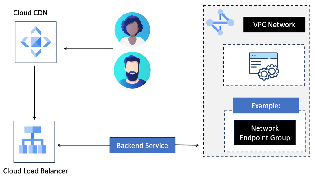
4. Content Delivery Networks (CDNs):
CDNs employ overlay networks to optimize content delivery by strategically distributing content across multiple servers in different geographic regions. By bringing content closer to end-users, CDNs reduce latency and improve performance. Overlay networks in CDNs enable efficient content caching, load balancing, and fault tolerance, resulting in faster and more reliable content delivery.
5. Overlay Multicast Networks:
Overlay multicast networks are designed to distribute data to multiple recipients simultaneously efficiently. These networks use overlay protocols to construct multicast trees and deliver data over these trees. Overlay multicast networks benefit applications such as video streaming, online gaming, and live events broadcasting, where data must be transmitted to many recipients in real-time.
Google Cloud CDN
**What is Google Cloud CDN?**
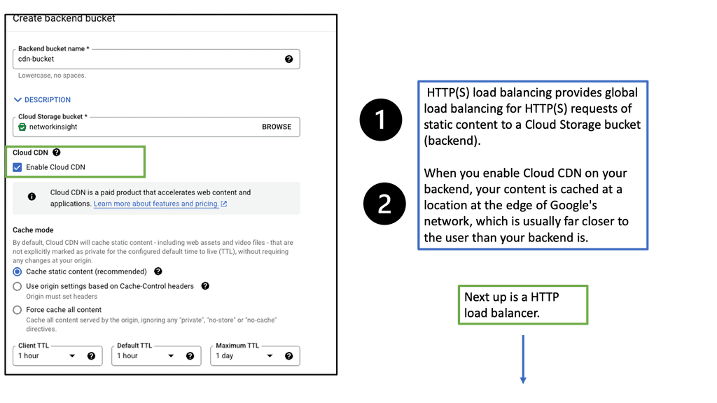
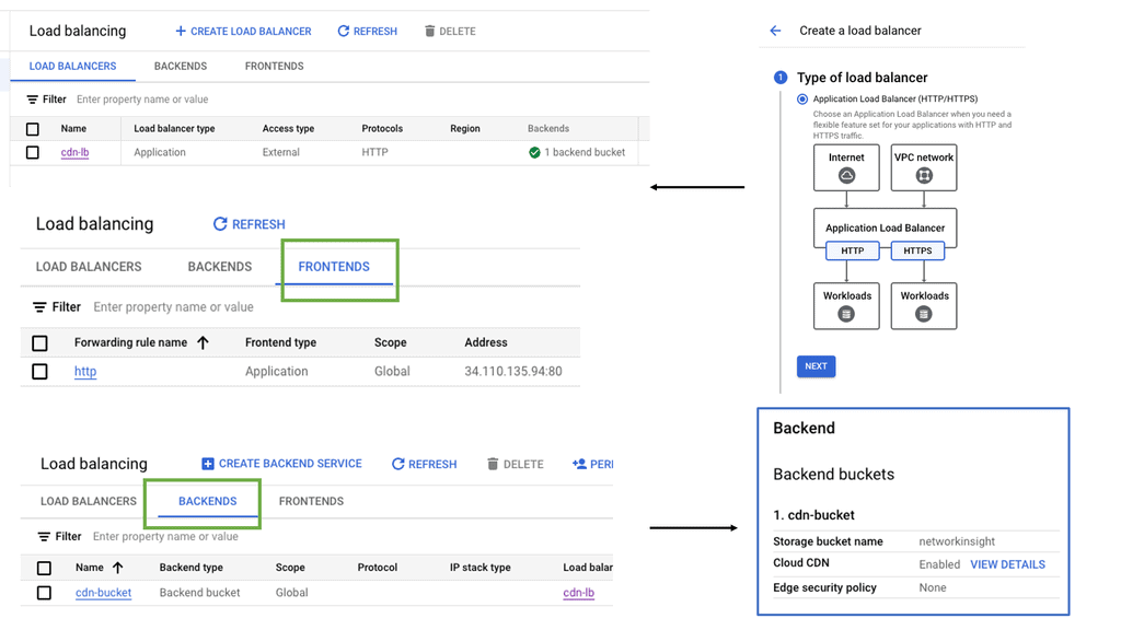
Google Cloud CDN is a globally distributed network of servers designed to cache and deliver content closer to the end-users, reducing latency and improving load times. By leveraging Google’s robust infrastructure, Cloud CDN allows businesses to serve their content quickly and reliably to users all over the world. This service is particularly beneficial for websites, APIs, and applications that experience high traffic or need to operate at peak performance levels.
**Key Features of Google Cloud CDN**
One of the standout features of Google Cloud CDN is its integration with Google Cloud’s services. This seamless connection means you can easily manage your CDN alongside other Google Cloud products, streamlining operations. Additionally, Google Cloud CDN offers features like SSL/TLS support, advanced caching capabilities, and custom domain support, ensuring secure and flexible content delivery.
Another crucial feature is the global reach of Google Cloud CDN. With points of presence (PoPs) strategically located around the world, content is delivered from the nearest server to the user, ensuring quick and reliable access. The network is designed to handle high volumes of traffic, making it ideal for businesses of any size.
**Benefits of Using Google Cloud CDN**
The benefits of adopting Google Cloud CDN are manifold. Firstly, it significantly reduces latency, ensuring that users have a smooth and fast experience. This is particularly vital for businesses that rely on web traffic to drive sales or engagement. Faster load times can lead to increased user satisfaction and higher conversion rates.
Secondly, Google Cloud CDN enhances security. By offloading traffic to edge servers, it acts as a protective layer against DDoS attacks, mitigating threats before they reach your core infrastructure. This added security is invaluable for businesses that handle sensitive data or rely on uptime for operational success.
Lastly, Google Cloud CDN offers cost efficiency. By using caching and strategically distributing content, it reduces the need for expensive bandwidth and server resources. This optimization can lead to significant cost savings, making it an attractive option for businesses looking to maximize their cloud investment.
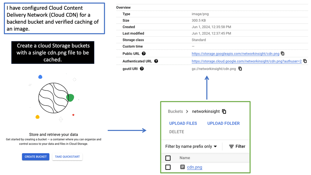
**How to Get Started with Google Cloud CDN**
Getting started with Google Cloud CDN is straightforward. First, you’ll need to set up a Google Cloud account if you don’t already have one. Once your account is ready, you can enable Cloud CDN through the Google Cloud Console. From there, you can configure your caching rules, secure your content with SSL/TLS, and monitor performance with Google Cloud’s comprehensive analytics tools.
To ensure optimal performance, it’s advisable to familiarize yourself with best practices for content caching and delivery. Google Cloud provides extensive documentation and support to help you make the most out of their CDN service.
Use Cases of Overlay Virtual Networking:
1. Multi-Tenancy: Overlay virtual networking provides an ideal solution for organizations to segregate their network resources securely. By creating virtual overlays, multiple tenants can coexist on a single physical network infrastructure without interference. This enables service providers and enterprises to offer distinct network environments to customers or departments while ensuring isolation and security.
2. Data Center Interconnect: Overlay virtual networking enables efficient and scalable data center interconnect (DCI). With traditional networking, interconnecting multiple data centers across geographies can be complex and costly. However, overlay virtual networking simplifies this process by abstracting the underlying physical infrastructure and providing a unified logical network. It allows organizations to seamlessly extend their networks across multiple data centers, enhancing workload mobility and disaster recovery capabilities.
3. Cloud Computing: Cloud computing heavily relies on overlay virtual networking to deliver agility and scalability. Cloud providers can dynamically provision and manage network resources by leveraging overlay networks, ensuring optimal customer performance and flexibility. Overlay virtual networking enables the creation of virtual networks that are isolated from each other, allowing for secure and efficient multi-tenant cloud environments.
4. Microservices and Containerization: The rise of microservices architecture and containerization has presented new networking challenges. Overlay virtual networking provides a solution by enabling seamless communication between microservices and containers, regardless of their physical location. It ensures that applications and services can communicate with each other, even across different hosts or clusters, without complex network configurations.
5. Network Segmentation and Security: Overlay virtual networking enables granular network segmentation, allowing organizations to implement fine-grained security policies. By creating overlay networks, administrators can isolate different workloads, departments, or applications, ensuring each segment has dedicated network resources and security policies. This enhances security by limiting the lateral movement of threats and reducing the attack surface.
Tunneling Protocols
Tunneling protocols play a crucial role in overlay virtual networks by facilitating the encapsulation and transportation of network packets over the underlying physical network. Popular tunneling protocols such as VXLAN (Virtual Extensible LAN), MPLS (Multiprotocol Label Switching ), NVGRE (Network Virtualization using Generic Routing Encapsulation), and Geneve provide the necessary mechanisms for creating virtual tunnels and encapsulating traffic.
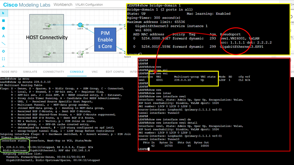
The Network Virtualization Edge (NVE) acts as the endpoint for the overlay virtual network. It connects the physical network infrastructure to the virtual network, ensuring seamless communication between the two. NVEs perform functions like encapsulation, decapsulation, and mapping virtual network identifiers (VNIs) to the appropriate virtual machines or containers.
Example: Point-to-Point GRE
GRE, or Generic Routing Encapsulation, is a tunneling protocol widely used in overlay networks. It encapsulates various network layer protocols within IP packets, enabling virtual point-to-point connections over an existing IP network. GRE provides a mechanism to extend private IP addressing schemes over public networks, facilitating secure and efficient communication between remote locations.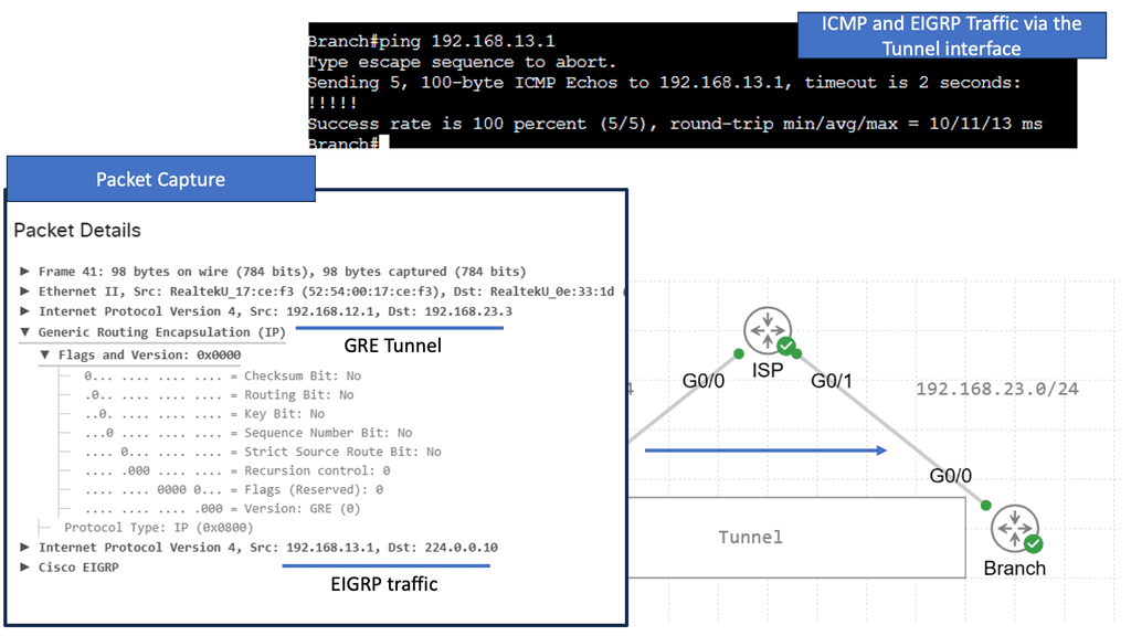
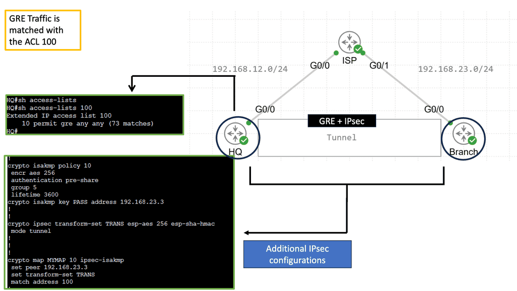
Example: GRE and IPSec
GRE and IPSEC often work together to create secure tunnels across public networks. GRE provides the means for encapsulating and carrying different protocols, while IPSEC ensures the confidentiality and integrity of the encapsulated packets. By combining the strengths of both protocols, organizations can establish secure connections that protect sensitive data and enable secure communication between remote networks.
The combination of GRE and IPSEC offers several benefits and finds applications in various scenarios. Some of the key advantages include enhanced security, scalability, and flexibility. Organizations can utilize this technology to establish secure site-to-site VPNs, remote access VPNs, and even to facilitate secure multicast communication. Whether connecting branch offices, enabling remote employee access, or safeguarding critical data transfers, GRE and IPSEC are indispensable tools.
Example: MPLS Overlay Tunneling
MPLS overlay tunneling is a technique that enables the creation of virtual private networks (VPNs) over existing network infrastructures. It involves encapsulating data packets within additional headers to establish tunnels between network nodes. MPLS, or Multiprotocol Label Switching, is a versatile technique that facilitates the forwarding of network packets. It operates at the OSI (Open Systems Interconnection) model’s layer 2.5, combining the benefits of both circuit-switching and packet-switching technologies. By assigning labels to data packets, MPLS enables efficient routing and forwarding, enhancing network performance.
**Overlay Network Control Plane**
The control plane in an overlay virtual network manages and maintains the overall network connectivity. It handles tasks such as route distribution, network mapping, and keeping the overlay network’s forwarding tables. Border Gateway Protocol (BGP) and Virtual Extensible LAN Segment Identifier (VXLAN VNI) provide the necessary control plane mechanisms. The network can adapt to changing conditions and optimize performance through centralized or distributed control plane architectures.
Components of the Overlay Network Control Plane
a) Controller: The controller serves as the core component of the control plane, acting as a centralized entity that orchestrates network operations. It receives information from network devices, processes it, and then disseminates instructions to ensure proper network functioning.
b) Routing Protocols: Overlay networks employ various routing protocols to determine the optimal paths for data transmission. Protocols like BGP, OSPF, and IS-IS are commonly used to establish and maintain routes within the overlay network.
c) Virtual Network Mapping: This component maps virtual network topologies onto the physical infrastructure. It ensures that virtual network elements are appropriately placed and interconnected, optimizing resource utilization while maintaining network performance.
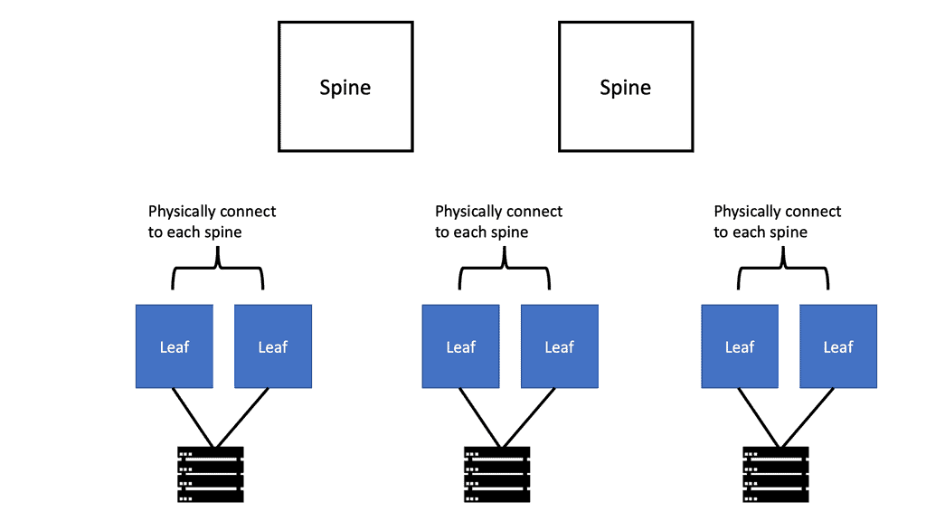
Underlay and Clos Fabric
The underlay of most modern data centers is a 3-stage or 5-stage Clos fabric, with the physical infrastructure and point-to-point Layer 3 interfaces between the spines and leaves. Network virtualization can be created by elevating the endpoints and applications connected to the network into this overlay, thus logically carving out different services on top of it.
Traditional data center network architectures, such as the three-tier architecture, were widely used. These architectures featured core, distribution, and access layers, each serving a specific purpose. However, as data traffic increased and workloads became more demanding, these architectures started to show limitations in terms of scalability and performance.
Introducing Leaf and Spine Architecture
Leaf and spine architecture emerged as a solution to overcome the shortcomings of traditional network architectures. This modern approach reimagines network connectivity by establishing a fabric of interconnected switches. The leaf switches act as access switches, while the spine switches provide high-speed interconnectivity between the leaf switches. This design increases scalability, reduces latency, and improves bandwidth utilization.
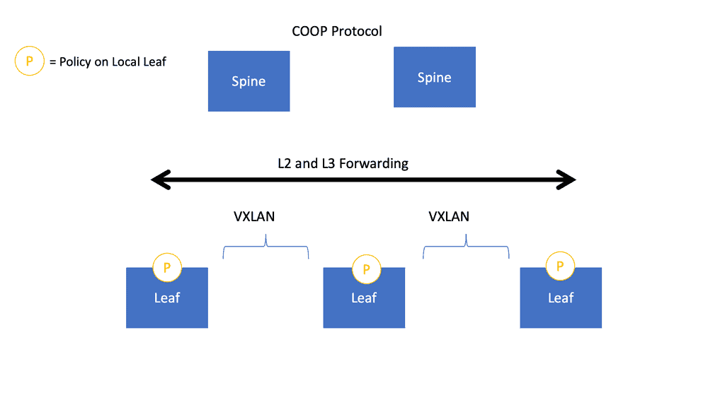
VXLAN and Leaf and Spine
In RFC 7348, a Virtual Extensible LAN (VXLAN) is a data plane encapsulation type capable of supporting Layer 2 and Layer 3 payloads. In addition to logically separating broadcast or bridging domains in a network, virtual LANs (VLANs) are limited in their scalability to 4K VLANs. By contrast, VXLAN provides a 24-bit VXLAN Network Identifier (VNI) in the VXLAN header, allowing the network administrator more flexibility to partition the network logically.
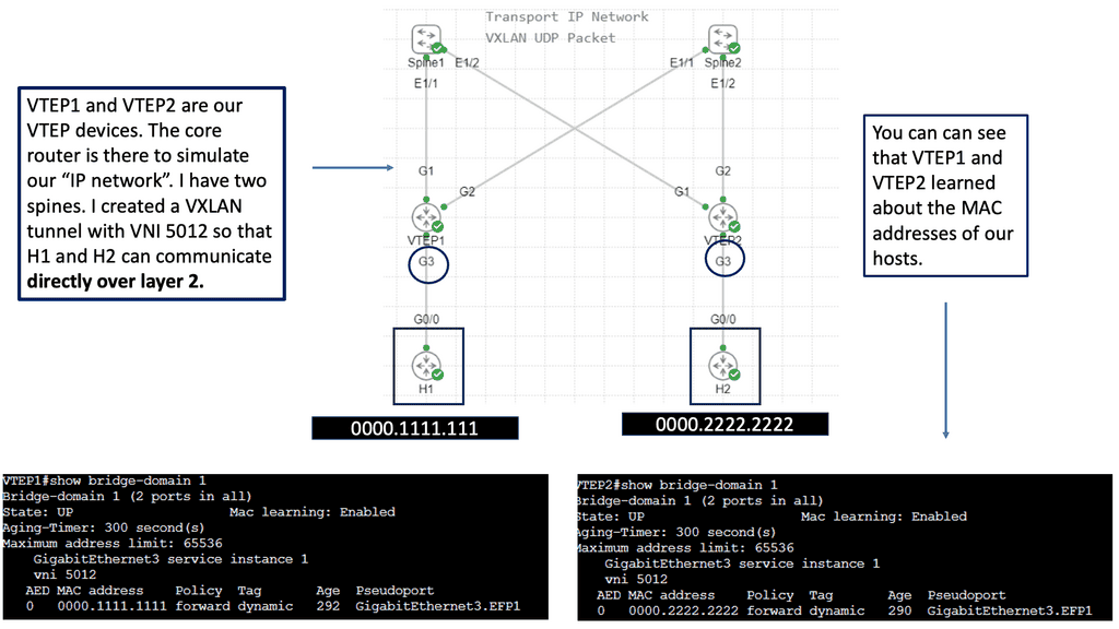
VXLAN is, in essence, a stateless tunnel originating at one endpoint and terminating at another because of its encapsulating trait. The VXLAN Tunnel Endpoints (VTEPs) are the endpoints that encapsulate and decapsulate the VXLAN tunnel. The first thing you need to understand about VXLAN is that these tunnels can originate and terminate on network devices or servers with the help of a virtual switch such as Open vSwitch, with a VXLAN module that is usually accelerated by hardware so that the CPU doesn’t have to process these packets in software.
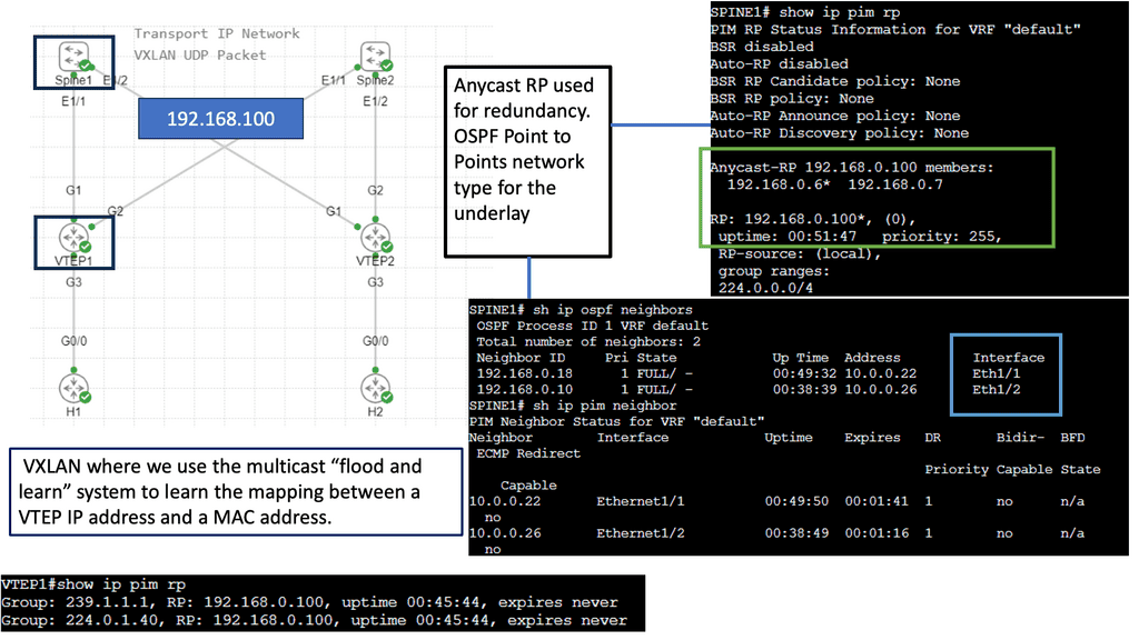
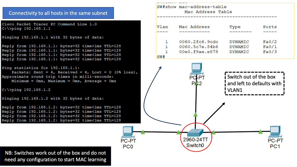
Example: VXLAN Flood and Learn
Understanding VXLAN Flood and Learn
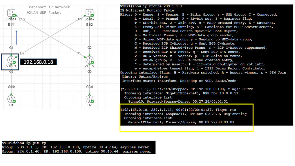
VXLAN Flood and Learn is a mechanism used in VXLAN networks to facilitate the dynamic learning of MAC addresses in a scalable manner. Traditionally, MAC learning relied on control-plane protocols, which could become a bottleneck in larger deployments. With VXLAN Flood and Learn, the burden of MAC address learning is offloaded to the data plane, allowing for greater scalability and efficiency.
Multicast plays a pivotal role in VXLAN Flood and Learn. It serves to transmit broadcast, unknown unicast, and multicast (BUM) traffic within the VXLAN overlay. By utilizing multicast, BUM traffic can be efficiently delivered to interested recipients across the VXLAN fabric, eliminating the need for flooding at Layer 2.
Adopting VXLAN Flood and Learn with Multicast brings several advantages to network operators. Firstly, it reduces the reliance on control-plane protocols, simplifying the network architecture and improving scalability. Additionally, it minimizes unnecessary traffic across the VXLAN fabric, resulting in enhanced efficiency. However, it’s essential to consider the scalability of the multicast infrastructure and the impact of multicast traffic on the underlying network.

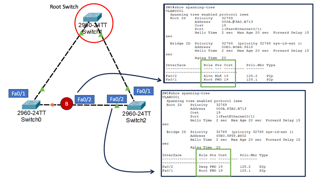
**VXLAN vs. Spanning Tree Protocol**
Now, let’s compare VXLAN and STP across various aspects:
Scalability: VXLAN provides unparalleled scalability by enabling the creation of up to 16 million logical networks, addressing the limitations of traditional VLANs. In contrast, STP suffers from scalability issues due to its limited VLAN range and the potential for network loops.
Efficiency: VXLAN optimizes network utilization by allowing traffic to be load-balanced across multiple paths, resulting in improved performance. STP, on the other hand, blocks redundant paths, leading to underutilization of available network resources.
Convergence Time: VXLAN exhibits faster convergence time compared to STP. With VXLAN, network reconfigurations can be achieved dynamically without service interruption, while STP requires considerable time for convergence, causing potential service disruptions.
Multicast Overlay
VXLAN encapsulates Ethernet frames within UDP packets, allowing virtual machines (VMs) to communicate across different physical networks or data centers seamlessly. When combined, multicast and VXLAN offer a robust solution for scaling network virtualization environments. Multicast efficiently distributes traffic across VXLAN tunnels, ensuring optimal delivery to multiple hosts. By leveraging multicast, VXLAN eliminates the need for unnecessary packet replication, reducing network congestion and enhancing overall performance.
Advantages of Overlay Virtual Networks
Enhanced Security and Isolation:
One key advantage of overlay virtual networks is their ability to provide enhanced security and isolation. Encapsulating traffic within virtual tunnels allows overlay networks to establish secure communication channels between network segments. This isolation prevents unauthorized access and minimizes the potential for network breaches.
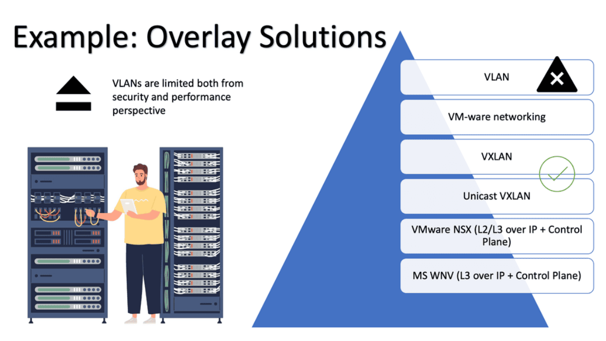
While VLANs offer flexibility and ease of network management, one of their significant disadvantages lies in their limited scalability. As networks expand and the number of VLANs increases, managing and maintaining the VLAN configurations becomes increasingly complex. Network administrators must carefully plan and allocate resources to prevent scalability issues and potential performance bottlenecks.
Simplified Network Management
Overlay virtual networks simplify network management. By decoupling the virtual network from the physical infrastructure, network administrators can easily configure and manage network policies and routing without affecting the underlying physical network. This abstraction layer streamlines network management tasks, resulting in increased operational efficiency.
Scalability and Flexibility
Scalability is a critical requirement in modern networks, and overlay virtual networks excel in this aspect. By leveraging the virtualization capabilities, overlay networks can dynamically allocate network resources based on demand. This flexibility enables seamless scaling of network services, accommodating evolving business needs and ensuring optimal network performance.
Performance Optimization
Overlay virtual networks also offer performance optimization features. By implementing intelligent traffic engineering techniques, overlay networks can intelligently route traffic and optimize network paths. This ensures efficient utilization of network resources and minimizes latency, resulting in improved application performance.
Advanced Topics
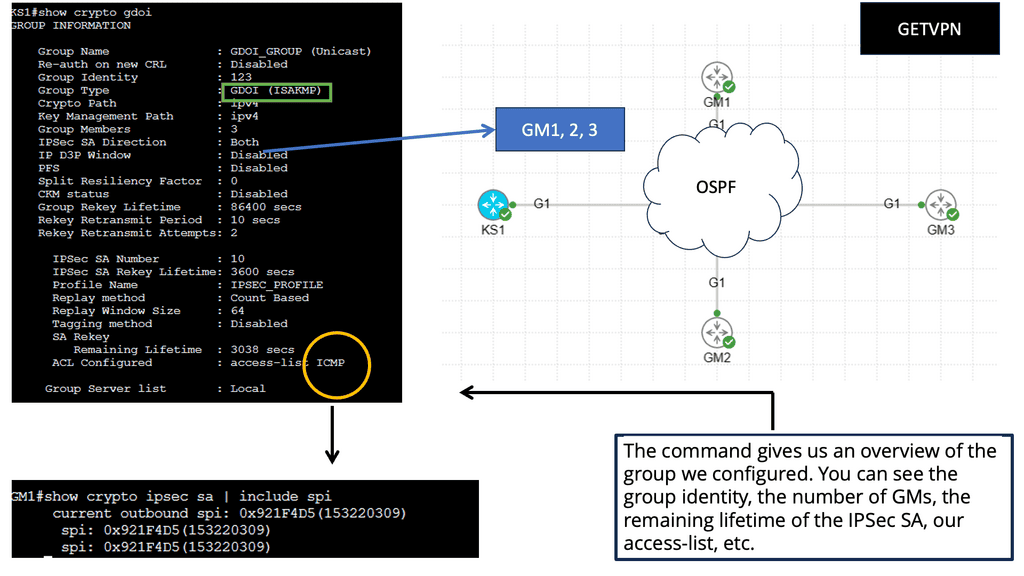
1. GETVPN:
Group Encrypted Transport VPN (GET VPN) is a set of Cisco IOS features that secure IP multicast group and unicast traffic over a private WAN. GET VPN secures IP multicast or unicast traffic by combining the keying protocol Group Domain of Interpretation (GDOI) with IP security (IPsec) encryption. With GET VPN, multicast and unicast traffic are protected without the need for tunnels, as nontunneled (that is, “native”) IP packets can be encrypted.
Key Components of Getvpn
GDOI Key Server: The GDOI Key Server is the central authority for key management in Getvpn. It distributes encryption keys to all participating network devices, ensuring secure communication. By centrally managing the keys, the GDOI Key Server simplifies adding or removing devices from the network.
Group Member: The Group Member is any device that is part of the Getvpn network. It can be a router, switch, or firewall. Group Members securely receive encryption keys from the GDOI Key Server and encrypt/decrypt traffic using these keys. This component ensures that data transmitted within the Getvpn network remains confidential and protected.
Group Domain of Interpretation (GDOI): The GDOI protocol is the backbone of Getvpn. It enables secure exchange and management between the GDOI Key Server and Group Members. Using IPsec for encryption and the Internet Key Exchange (IKE) protocol for key establishment, GDOI ensures the integrity and confidentiality of data transmitted over the Getvpn network.
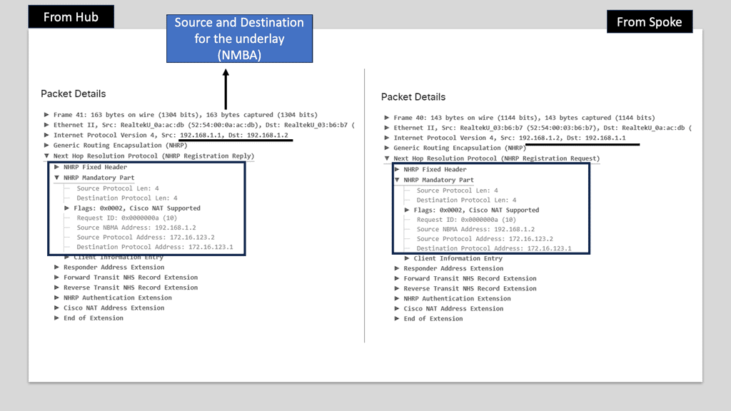
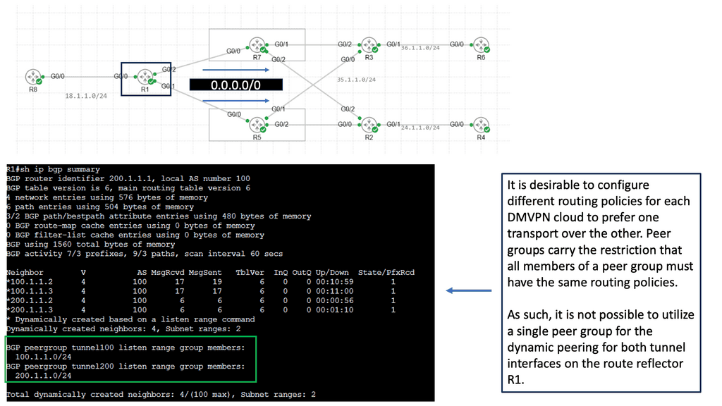
2. DMVPN
DMVPN is a scalable and flexible networking solution that allows the creation of secure virtual private networks over a public infrastructure. Unlike traditional VPNs, DMVPN dynamically builds tunnels between network endpoints, providing a more efficient and cost-effective approach to network connectivity.
The underlay network forms the foundation of DMVPN. It represents the physical infrastructure that carries IP traffic between different sites. This network can be based on various technologies, such as MPLS, the Internet, or even a mix of both. It provides the necessary connectivity and routing capabilities to establish communication paths between the DMVPN sites.
While the underlay takes care of the physical connectivity, the overlay network is where DMVPN truly shines. This layer is built on top of the underlay and is responsible for creating a secure and efficient virtual network. Through the magic of tunneling protocols like GRE (Generic Routing Encapsulation) or IPsec (Internet Protocol Security), DMVPN overlays virtual tunnels over the underlay network, enabling seamless communication between sites.
1. Multipoint GRE Tunnels: One key component of DMVPN is the multipoint GRE (mGRE) tunnels. These tunnels allow multiple sites to communicate with each other over a shared IP network. Using a single tunnel interface makes scaling the network easier and reduces administrative overhead.
2. Next-Hop Resolution Protocol (NHRP): NHRP is another essential component of DMVPN. It allows mapping the tunnel IP address to the remote site’s physical IP address. This dynamic mapping allows efficient routing and eliminates the need for static or complex routing protocols.
3. IPsec Encryption: To ensure secure communication over the public network, DMVPN utilizes IPsec encryption. IPsec encrypts the data packets traveling between sites, making it nearly impossible for unauthorized entities to intercept or tamper with the data. This encryption provides confidentiality and integrity to the network traffic.


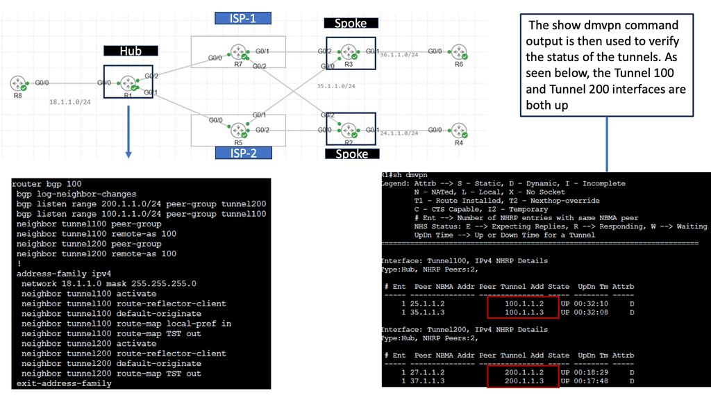
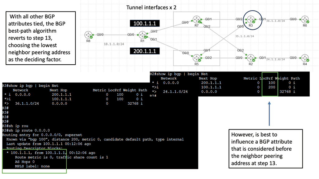
The Single Hub Dual Cloud Architecture
The single-hub dual cloud architecture takes the benefits of DMVPN to the next level. With this configuration, a central hub site is a connection point for multiple cloud service providers (CSPs). This architecture enables businesses to leverage the strengths of different CSPs simultaneously, ensuring high availability and redundancy.
One key advantage of the single hub dual cloud architecture is improved reliability. By distributing traffic across multiple CSPs, businesses can mitigate the risk of service disruption and minimize downtime. Additionally, this architecture provides enhanced performance by leveraging the geographic proximity of different CSPs to various remote sites.
Implementing the single-hub dual cloud architecture requires careful planning and consideration. Factors such as CSP selection, network design, and security measures must all be considered. It is crucial to assess your organization’s specific requirements and work closely with network engineers and CSP providers to ensure a smooth and successful deployment.

**DMVPN vs GETVPN**
DMVPN and GETVPN are two VPN technologies commonly used in Enterprise WAN setups, especially when connecting many remote sites to one hub. Both GETVPN and DMVPN technologies allow hub-to-spoke and spoke-to-spoke communication. Whenever any of these VPN solutions are deployed, especially on Cisco Routers, a security license is an additional overhead (cost).
Tunnel-less VPN technology, GETVPN, provides end-to-end security for network traffic across fully mesh topologies. DMVPN enables full mesh connectivity with a simple hub-and-spoke configuration. In DMVPN, IPsec tunnels are formed over dynamically/statically addressed spokes.
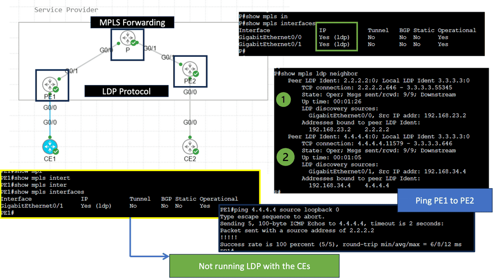
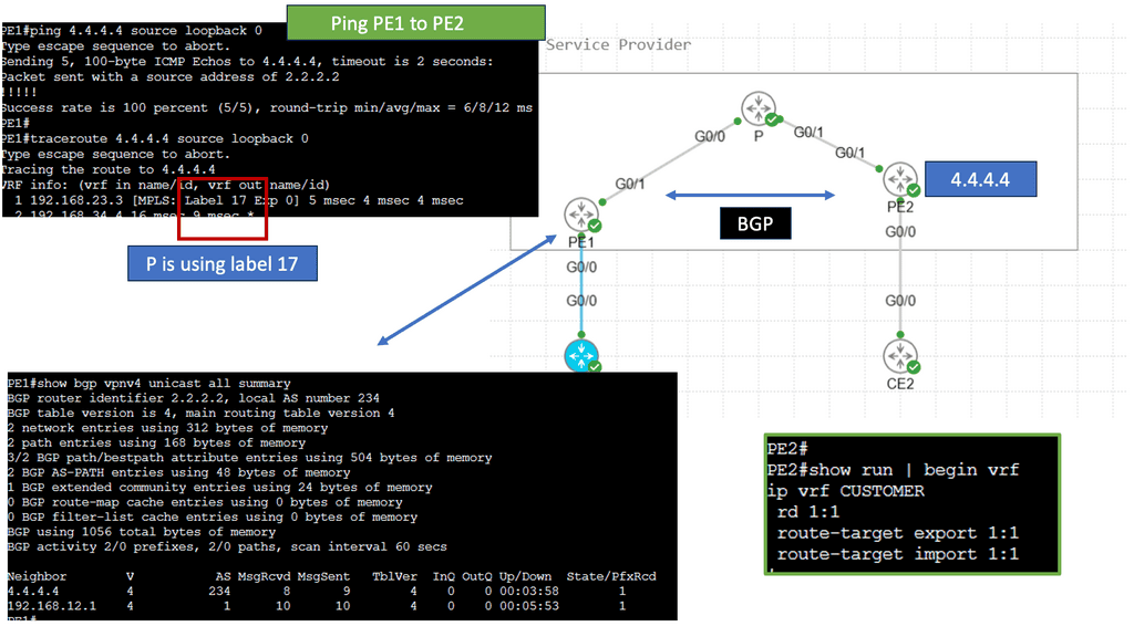
3. MPLS VPN
At its core, MPLS VPN is a technique that utilizes MPLS labels to route data securely over a shared network infrastructure. It enables the creation of virtual private networks, allowing businesses to establish private and isolated communication channels between their various sites. By leveraging MPLS technology, MPLS VPN ensures optimal performance, service quality, and enhanced data transmission security.
MPLS VPN Components
1. Provider Edge (PE) Routers: PE routers are located at the edge of the service provider’s network. They act as the entry and exit points for the customer’s data traffic. PE routers are responsible for applying labels to incoming packets and forwarding them based on the predetermined VPN routes.
2. Customer Edge (CE) Routers: CE routers are located at the customer’s premises and connect the customer’s local network to the service provider’s MPLS VPN network. They establish a secure connection with the PE routers and exchange routing information to ensure proper data forwarding.
3. Provider (P) Routers: P routers are the backbone of the service provider’s network. They form the core network and forward labeled packets between the PE routers. P routers do not participate in VPN-specific functions and only focus on efficient packet forwarding.
**Label Distribution Protocol (LDP)**
LDP is a key component of MPLS VPNs. It distributes labels across the network, ensuring each router has the necessary information to label and forward packets correctly. LDP establishes label-switched paths (LSPs) between PE routers, providing the foundation for efficient data transmission.
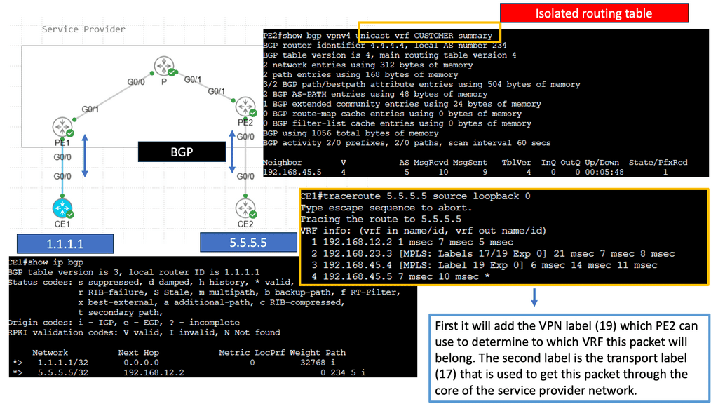
**Virtual Routing and Forwarding (VRF)**
VRF is a technology that enables the creation of multiple virtual routing tables within a single physical router. Each VRF instance represents a separate VPN, allowing for isolation and secure communication between different customer networks. VRF ensures that data from one VPN does not mix with another, providing enhanced privacy and security.
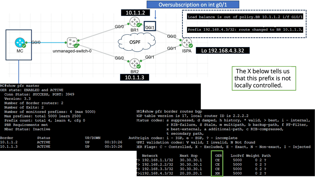
Use Case: Understanding Performance-Based Routing
Performance-based routing is a dynamic approach to network routing that considers real-time metrics such as latency, packet loss, and available bandwidth to determine the most optimal path for data transmission. Unlike traditional static routing protocols that rely on predetermined routes, performance-based routing adapts to the ever-changing network conditions, ensuring faster and more reliable data delivery.
Enhanced Network Performance: By leveraging performance-based routing algorithms, businesses can significantly improve network performance. This approach’s dynamic nature allows for intelligent decision-making, routing data through the most efficient paths, and avoiding congested or unreliable connections. This results in reduced latency, improved throughput, and enhanced us.
Cost Savings: Performance-based routing not only improves network performance but also leads to cost savings. Businesses can minimize bandwidth consumption by optimizing data transmission paths, effectively reducing operational expenses. Additionally, organizations can make more efficient use of their network infrastructure by avoiding underperforming or expensive routes.
Related: Before you proceed, you may find the following useful:
Concept of network virtualization
It’s worth mentioning that network virtualization is nothing new. The most common forms of network virtualization are virtual LANs (VLANs), virtual private networks (VPNs), and Multiprotocol Label Switching (MPLS). VLAN has been the first to extract the location of Layer 2 connectivity across multiple Layer 2 switches. VPN enables overlay networks across untrusted networks such as the WAN, while MPLS segments traffic based on labels.
These technologies enable the administrators to physically separate endpoints into logical groups, making them behave like they are all on the same local (physical) segment. The ability to do this allows for much greater efficiency in traffic control, security, and network management.
- Enhanced Connectivity:
One of the primary advantages of network overlay is its ability to enhance connectivity. By creating a virtual network layer, overlay networks enable seamless communication between devices and applications, irrespective of their physical location.
This means organizations can effortlessly connect geographically dispersed branches, data centers, and cloud environments, fostering collaboration and resource sharing. Moreover, network overlays offer greater flexibility by allowing organizations to dynamically adjust and optimize their network configurations to meet evolving business needs.
- Improved Scalability:
Traditional network infrastructures often struggle to keep up with the increasing demands of modern applications and services. Network overlay addresses this challenge by providing a scalable solution. By decoupling the virtual network from the physical infrastructure, overlay networks allow for more efficient resource utilization and easier scaling.
Organizations can easily add or remove network elements without disrupting the entire network. As a result, network overlays enable organizations to scale their networks rapidly and cost-effectively, ensuring optimal performance even during peak usage periods.
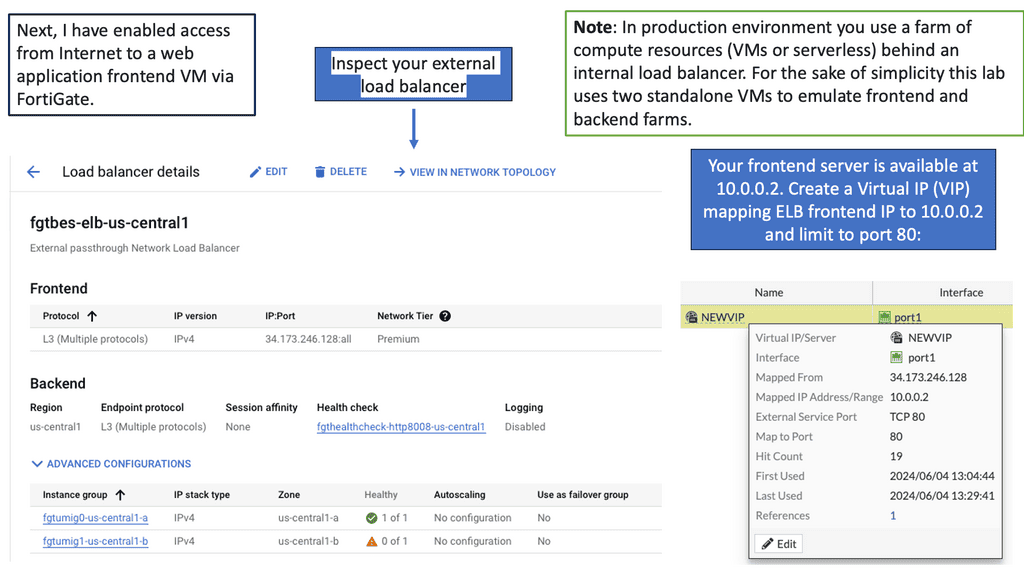
Tailored load balancing
Some customers may not require cloud load balancing services provided by the cloud services if they have optimized web delivery by deploying something like Squid or NGINX. Squid is a caching proxy that improves web request response times by caching frequently requested web pages. NGINX ( open source reverse proxy ) is used to load balance Hypertext Transfer Protocol ( HTTP ) among multiple servers.
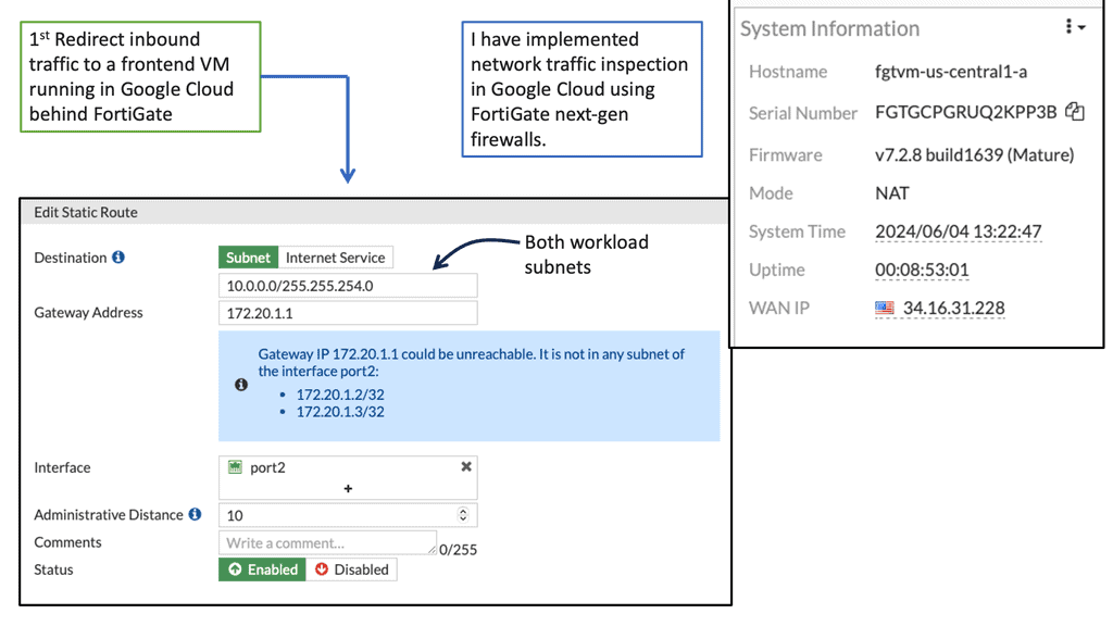
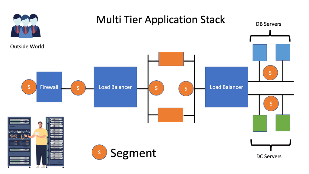
Example: Traffic flow and the need for a virtual overlay
Traffic would flow to Web servers and trigger application and database requests. Each tier requires different segments, and in large environments, the limitations of using VLANs to create these segments will bring both scalability and performance problems.
This is why we need virtual overlay solutions. These subnets require Layer 3 and sometimes Layer 2 ( MAC ). Layer 2 connectivity might be for high availability services that rely on gratuitous Address Resolution Protocol ( ARP ) between devices or some other non-routable packet that can not communicate over IP. If the packet is not Layer 3 routable, it needs to communicate via Layer 2 VLANs.
Scalability and Security Concerns
The weakest link in a security paradigm is the lowest application in that segment. Make each application an independent tenant so all other applications are unaffected if a security breach or misuse occurs in one application stack.
Designers should always attempt to design application stacks to minimize beachheading, i.e., an attacker compromising one box and using it to jump to another quickly. Public and private clouds should support multi-tenancy with each application stack.
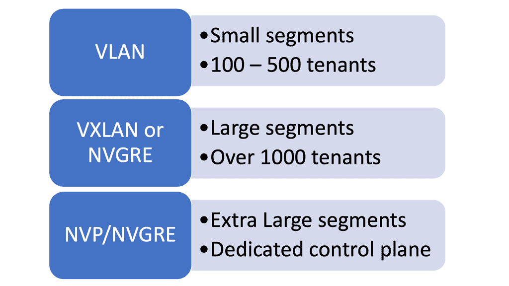
However, scalability issues arise when you deploy each application as an individual segment. For example, customer X’s cloud application requires four segments; 4000 VLANs soon become 1000 applications. Media Access Control ( MAC ) visibility has an entire reach throughout Layer 2 domains.
Some switches support a low count number of MAC addresses. When a switch reaches its MAC limit, it starts flooding packets, increasing network load and consuming available bandwidth that should be used for production services.
…current broadcast domains can support … around 1,000 end hosts in a single bridged LAN of 100 bridges” (RFC 5556 – TRILL)
NIC in promiscuous mode and failure domains
Server administrators configure server NICs in promiscuous mode to save configuration time. NICs in promiscuous mode look at all frames passing even when the frame is not destined for them. Network cards acting in promiscuous mode are essentially the same as having one VLAN spanning the entire domain. Sniffer products set promiscuous modes to capture all data on a link and usually only act in this mode for troubleshooting purposes.
A well-known issue with Layer 2 networks is that they present a single failure domain with extreme scalability and operational challenges. This is related to Layer 2 Spanning Tree Protocol ( STP ); THRILL is also susceptible to broadcast storms and network meltdowns.
The rise of overlay virtual networks
Previously discussed scalability and operational concerns force vendors to develop new data center technologies. One of the most prevalent new technologies is overlay virtual networks, tunneling over IP. An overlay is a tunnel between two endpoints, allowing frames to be transported. The beauty of overlay architectures is that they enable switch table sizes not to increase as the number of hosts attached increases.
Vendors’ Answer: Virtual Overlay Solutions

Virtual Overlay Solution: Keep complexity to the edges.
Ideally, we should run virtual networks over IP like SKYPE runs Voice over IP. The recommended design retains complexity at the network’s edge; the IP transport network provides IP transport. A transport network does not need to be a Layer 2 network and can have as many IP subnets and router hops.
All data ( storage, vMotion, user traffic ) traffic becomes an IP application. The concept resembles how Border Gateway Protocol ( BGP ) applies to TCP. End hosts carry out encapsulation and use the network for transport. Again, complexity is at the edge, similar to the Internet. Keeping complexity to the edge makes Layer 3 fabrics efficient and scalable.
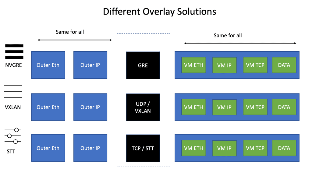
VXLAN, STT, and ( NV ) GRE
Numerous encapsulation methods can tunnel over the IP core. This is known as virtual overlay networking and includes VXLAN, STT, and ( NV ) GRE. The main difference between these technologies is the encapsulation method and minor technological differences with TCP offload and load balancing.
The Recommended Design: Leaf and Spine.
Like the ACI network, virtual overlay networks work best with Leaf and Spine fabric architectures. Leaf and Spine designs guarantee any two endpoints get equal bandwidth. VMs on the same Top-of-Rack ( ToR ) switch will have access to more bandwidth than if the VM had to communicate across the Spine layer.
Overlay networks assume that the underlying network has a central endpoint. The transport network should avoid oversubscription as much as possible. If security concerns you, you can always place similar VM appliances on dedicated clusters, one type per physical server.
( NV ) GRE, VXLAN, and STT do not have an built-in security features meaning the transport network MUST be secure.
TCP offload, load balancing & scale-out NAT
TCP can push huge segments down the physical NIC and slice the packet into individual TCP segments, improving TCP performance. For example, you can push 10Gbps from a VM with TCP offload. The problem is that NICs only support VLANs and not VXLANs.
NICIRA added another header in front of TCP segments. TCP is embedded in another TCP. Now, you can use the existing NIC to slice the current TCP segment into smaller TCP segments. It is dramatically improving performance.
STT and VXAN
STT and VXAN can use 5-tuple load balancing as they use port numbers. Therefore, traffic sent between a pair of VMs can use more than one link in the network. Unfortunately, not many switches can load balance based on the GRE payload used by NVGRE.
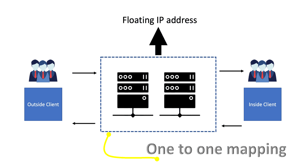
Scale-out NAT is difficult to implement as an asymmetric path is not guaranteed. Furthermore, the shared state is tied to an outside IP address, which limits scale-out options. To scale out effectively, the state has to be spread across all members of the NAT cluster. The new approach uses floating public IP addresses and one-to-one mapping between floating IP and the private IP address inside—there is no state due to the one-to-one mapping.
Distributed layer 2 & layer 3 forwarding
They distributed Layer 2 forwarding ( data plane ): Most Overlays offer distributed Layer 2 forwarding. VM can be sent to VM in the same segment. The big question is how they distribute MAC to VTEP – some use multicast and traditional Ethernet flooding, while others use control planes. The big question is how scalable is the control plane.
Distributed Layer 3 forwarding ( data plane ): On the other hand, if you have multiple IP subnets between segments ( not layer 2 ), you need to forward between them. The inter-subnet must not be a choke point. If your data center has lots of intra-traffic ( East to West traffic), avoid centralized inter-subnet forwarding, which will quickly become a traffic choke point.
The router will process ARP if you are doing Layer 3 forwarding. But if you are doing a mix of Layer 2 and 3, make sure you can reduce the flooding by intercepting ARP requests and caching ARP replies, known as distributed ARP Caching.
**Scale-out control plane**
Initial overlays used multicast and Ethernet-like learning. Now, some vendors are using controller-based overlays. Keep in mind that the controller can now become a scalability bottleneck. However, many vendors, such as Cisco ACI, can scale the controllers and have a quorum.
Efficient controller scalability is seen when controllers do not participate in the data plane ( do not reply to ARP ). This type of controller scales better than controllers that intercept data plane packets and perform data plane activity. So, the data plane will not be affected if a controller is offline. In the early days of Sofware-Defined Networking, this was not the case. If the controller was down, the network was down.
Scale-out controllers
Attempt to design scale-out controllers by building a cluster of controllers and having some protocol running between them. You now have clear failure domains. For example, controller A looks after VM segment A and Controller B, and control looks after VM segment B. For cloud deployments in multiple locations, deploy multiple controller clusters in each location.
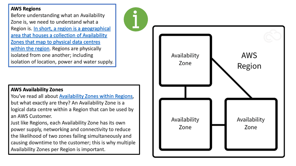
Availability zones
Design availability zones with hierarchical failure domains by splitting infrastructures into regions. Problems arising in one region do not affect all other regions. You have one or more availability zones within an area for physical and logical isolation.
Availability zones limit the impact of a failure in a failure domain. An example of a failure domain could be a VLAN experiencing a broadcast storm. Attempt to determine the span of VLANs across availability zones—define VLANs to one-ToR switch. Never stretch VLANs as you create a single failure domain by merging two zones.
Do not stretch a VLAN across multiple availability zones. This is why we have network overlays in the first place, so we don’t need to stretch VLAN across the data center. For example, VXLAN uses the VNI to differentiate between Layer 2 and Layer 3 traffic over a routed underlay. We can use VXLAN as the overlay network to span large Layer 2 domains over a routed core.
Network Overlay Controllers
As a final note on controllers, controller-based SDN networks participate in data planes and perform activities such as MAC learning and ARP replies. As mentioned, this is not common nowadays but was at the start of the SDN days. If the controller performs activities such as MAC learning and APR replies and the controller fails, then you have network failure.
The more involved the controller is in the forwarding decisions, the worse the outage can be. All overlay networking vendors nowadays have controllers that set up the control plane so the data plane can forward traffic without getting involved in data plane activity. This design also allows the controller to be scaled without affecting the data plane activity.
Closing Point: Overlay Virtual Networks
Overlay virtual networking is a method where a virtual network is built on top of an existing physical network. This abstraction allows for greater flexibility in managing and deploying network resources. By decoupling the physical infrastructure from the network’s logical topology, businesses can create complex network architectures without the need to reconfigure physical hardware. This is particularly advantageous in environments like data centers, where dynamic and scalable network configurations are essential.
The primary advantage of overlay virtual networking lies in its ability to simplify and streamline network management. With overlays, network administrators can easily create, modify, and manage network segments without altering the underlying physical infrastructure. Additionally, overlay networks provide enhanced security through network segmentation, allowing for isolated virtual networks within the same physical environment. This capability reduces the risk of unauthorized access and data breaches.
Overlay virtual networking is increasingly being adopted in various sectors, including cloud computing, data centers, and enterprise networks. For cloud service providers, overlays enable the rapid deployment of virtual networks for different customers, ensuring that resources are efficiently utilized while maintaining customer privacy. In data centers, overlay networks facilitate the creation of agile and scalable environments to accommodate fluctuating workloads and demands. Enterprises, on the other hand, leverage overlays to integrate multiple branch offices seamlessly into a cohesive network, enhancing communication and collaboration.
While overlay virtual networking offers numerous benefits, it’s not without its challenges. Network administrators must consider factors such as increased complexity in troubleshooting, potential performance issues due to additional encapsulation, and the need for advanced skills to manage and implement overlay technologies effectively. It’s crucial for organizations to weigh these considerations against the benefits to determine the best approach for their specific needs.