
The Role of Routing Logic
A Layer 3 Data Center is a type of data center that utilizes Layer 3 switching technology to provide network connectivity and traffic control. It is typically used in large-scale enterprise networks, providing reliable services and high performance.
Layer 3 Data Centers are differentiated from other data centers using Layer 3 switching. Layer 3 switching, also known as Layer 3 networking, is a switching technology that operates at the third layer of the Open Systems Interconnection (OSI) model, the network layer. This switching type manages network routing, addressing, and traffic control and supports various protocols.
Note: Routing Protocols
At its core, a Layer 3 data center is designed to operate at the network layer of the OSI (Open Systems Interconnection) model. This means it is responsible for routing data packets across different networks, rather than just switching them within a single network.
By leveraging routing protocols like BGP (Border Gateway Protocol) and OSPF (Open Shortest Path First), Layer 3 data centers facilitate more efficient and scalable networking solutions. This capability is crucial for businesses that require seamless connectivity across multiple sites and cloud environments.
Key Features and Architecture:
– Layer 3 data centers are designed with several key features that set them apart. Firstly, they employ advanced routing protocols and algorithms to efficiently handle network traffic. Additionally, they integrate firewall and security mechanisms to safeguard data and prevent unauthorized access. Layer 3 data centers also offer scalability, enabling seamless expansion and accommodating growing network demands.
– The utilization of Layer 3 data centers brings forth a myriad of advantages. Firstly, they enhance network performance by reducing latency and improving packet delivery. With their intelligent routing capabilities, they optimize the flow of data, resulting in faster and more reliable connections. Layer 3 data centers also enhance network security, providing robust protection against cyber threats and ensuring data integrity.
– Layer 3 data centers find extensive applications in various industries. They are particularly suitable for large enterprises with complex network architectures, as they provide the necessary scalability and flexibility. Moreover, Layer 3 data centers are instrumental in cloud computing environments, enabling efficient traffic management and interconnectivity between multiple cloud platforms.
Example Technology: BGP Route Reflection


Key Features and Functionalities:
1. Network Routing: Layer 3 data centers excel in routing data packets across networks, using advanced routing protocols such as OSPF (Open Shortest Path First) and BGP (Border Gateway Protocol). This enables efficient traffic management and optimal utilization of network resources.
2. IP Addressing: Layer 3 data centers assign and manage IP addresses, allowing devices within a network to communicate with each other and external networks. IP addressing helps identify and locate devices, ensuring reliable data transmission.
3. Interconnectivity: Layer 3 data centers provide seamless connectivity between different networks, whether they are local area networks (LANs), wide area networks (WANs), or the internet. This enables organizations to establish secure and reliable connections with their branches, partners, and customers.
4. Load Balancing: Layer 3 data centers distribute network traffic across multiple servers or network devices, ensuring that no single device becomes overwhelmed. This helps to maintain network performance, improve scalability, and prevent bottlenecks.
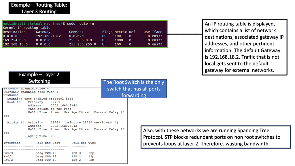
**Recap: Layer 3 Routing**
Layer 3 routing operates at the network layer of the OSI model and is responsible for forwarding data packets based on logical addressing. Routers are the primary devices that perform layer 3 routing. They use routing tables and algorithms to determine the best path for data to reach its intended destination. Layer 3 routing offers several advantages, including:
Scalability and Flexibility: Layer 3 routing allows for the creation of complex networks by connecting multiple subnets. It enables different network protocols and supports the interconnection of diverse networks, such as LANs and WANs.
Efficient Network Segmentation: Layer 3 routing facilitates network segmentation, which enhances security and performance. By dividing an extensive network into smaller subnets, layer 3 routing reduces broadcast traffic and isolates potential network issues.
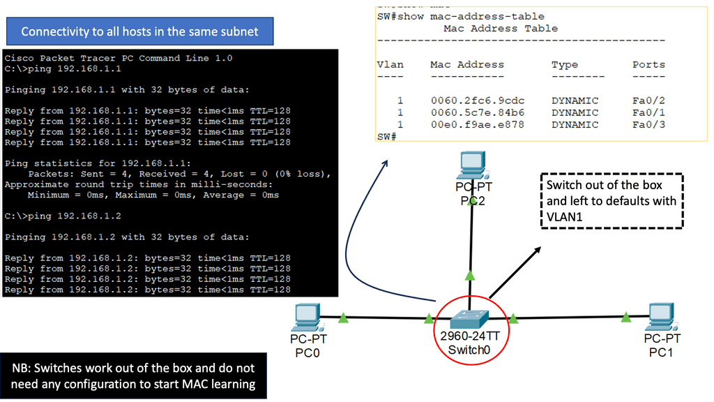
**Recap: Layer 2 Switching**
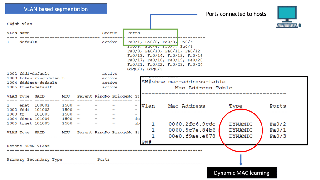
Layer 2 switching operates at the data link layer of the OSI model, facilitating the forwarding of data packets based on Media Access Control (MAC) addresses. Unlike layer 3 switching, which relies on IP addresses, layer 2 switching enables devices within the same local network to communicate directly without routing through layer 3 devices such as routers. This direct communication results in faster and more efficient data transmission.
Broadcast Domain Segmentation: Layer 2 switching allows for segmenting broadcast domains, isolating network traffic within specific segments. This segmentation enhances network security by preventing broadcast storms and minimizing the impact of network failures.
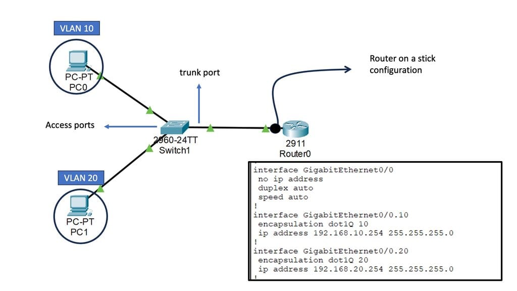
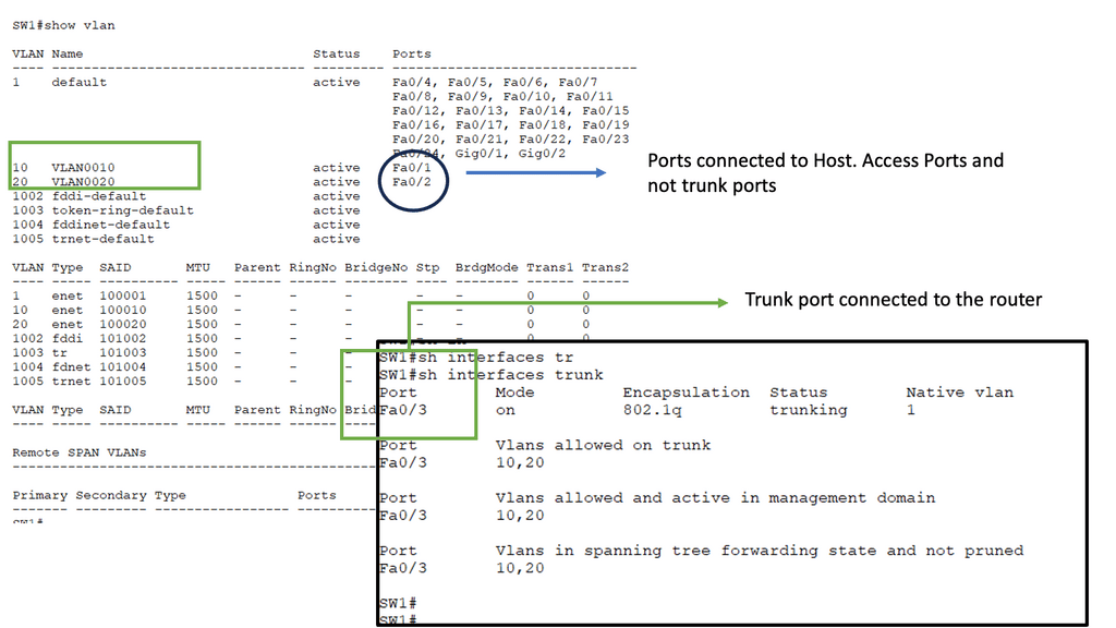
VLANs and Layer 2 Switching
Virtual LANs (VLANs): VLANs enable the logical segmentation of a physical network into multiple virtual networks. Layer 2 switching supports VLANs, allowing for the creation of separate broadcast domains and providing enhanced network security and flexibility.
Inter-VLAN Routing: Layer 2 switches equipped with Layer 3 capabilities can perform inter-VLAN routing, enabling communication between VLANs. This functionality is crucial in more extensive networks where traffic segregation is necessary while allowing inter-VLAN communication.
Example Layer 3 Technology: Layer 3 Etherchannel
Layer 3 Etherchannel is a networking technology that bundles multiple physical links into one logical one. Unlike Layer 2 Etherchannel, which operates at the data link layer, Layer 3 Etherchannel operates at the network layer. It provides load balancing, redundancy, and enhanced bandwidth utilization for network devices.
Careful configuration is necessary to maximize Layer 3 Etherchannel. This section will explore critical considerations, including selecting the appropriate load-balancing algorithm, configuring IP addressing, and setting up routing protocols. We will also discuss the importance of consistent configuration across all participating devices to ensure seamless operation.

**Understanding Layer 3 Etherchannel Load Balancing**
Layer 3 Etherchannel is a method of bundling multiple physical links between switches into a single logical link. It enables the distribution of traffic across these links, thereby ensuring effective load balancing. By utilizing Layer 3 Etherchannel, network administrators can achieve improved bandwidth utilization, increased redundancy, and enhanced fault tolerance.
Configuring Layer 3 Etherchannel load balancing involves several important considerations. First, choosing an appropriate load-balancing algorithm that suits the specific network requirements is crucial. The available options, such as source-destination IP address or source-destination MAC address, offer different advantages and trade-offs. Additionally, attention should be given to the number of links bundled in the Etherchannel and the overall capacity and capabilities of the involved switches.
Network Connectivity Center
### Understanding Google Network Connectivity Center (NCC)
Google Network Connectivity Center is a unified platform that allows organizations to manage, monitor, and optimize their network connections across different environments. Whether connecting on-premises data centers, branch offices, or cloud resources, NCC provides a centralized hub for network management. It simplifies the complexities of networking, offering a cohesive solution that integrates seamlessly with Google Cloud.

### Key Features of NCC
1. **Centralized Management**: NCC offers a single pane of glass for managing network connections, making it easier to oversee and control networking across multiple environments. This centralized approach enhances visibility and simplifies troubleshooting.
2. **Interconnectivity**: With NCC, businesses can establish secure, high-performance connections between their on-premises infrastructure and Google Cloud. This interconnectivity ensures that data flows smoothly and securely, regardless of the location.
3. **Scalability and Flexibility**: NCC’s architecture supports scalability, allowing businesses to expand their network reach as they grow. Its flexible design ensures that it can adapt to changing needs, providing consistent performance even under varying workloads.


### Benefits of Using NCC
1. **Enhanced Performance**: By optimizing network paths and providing direct connections, NCC reduces latency and improves overall network performance. This is crucial for applications requiring real-time data processing and low-latency communication.
2. **Increased Security**: NCC employs robust security measures to protect data as it traverses the network. From encryption to secure access controls, NCC ensures that sensitive information remains safeguarded.
3. **Cost Efficiency**: By consolidating network management and optimizing resource usage, NCC can lead to significant cost savings. Organizations can reduce expenses associated with maintaining multiple network management tools and streamline their operational costs.
High-Performance Routers and Switches
Layer 3 Data Centers are typically characterized by their use of high-performance routers and switches. These routers and switches are designed to deliver robust performance, scalability, and high levels of security. In addition, by using Layer 3 switching, these data centers can provide reliable network services such as network access control, virtual LANs, and Quality of Service (QoS) management.
Understanding High Performance Routers
Routers are the digital traffic cops of the internet, directing data between devices and networks. High performance routers take this role to another level by offering faster speeds, increased bandwidth, and enhanced security features. These routers are equipped with advanced technologies like MU-MIMO and beamforming, which ensure that multiple devices can connect simultaneously without any loss in speed or quality. This is particularly vital in environments where numerous devices are constantly online, such as smart homes and large offices.
The Role of Switches in Connectivity
Switches, on the other hand, act as the backbone of local area networks (LANs), connecting multiple devices within a single network while managing data traffic efficiently. High performance switches are designed to handle large volumes of data with minimal latency, making them ideal for businesses and enterprises that rely on real-time data processing. They support greater network flexibility and scalability, allowing networks to expand and adapt to growing demands without compromising performance.
**Benefits of Layer 3 Data Centers**
1. Enhanced Performance: Layer 3 data centers optimize network performance by efficiently routing traffic, reducing latency, and ensuring faster data transmission. This results in improved application delivery, enhanced user experience, and increased productivity.
2. Scalability: Layer 3 data centers are designed to support network growth and expansion. Their ability to route data across multiple networks enables organizations to scale their operations seamlessly, accommodate increasing traffic, and add new devices without disrupting the network infrastructure.
3. High Security: Layer 3 data centers provide enhanced security measures, including firewall protection, access control policies, and encryption protocols. These measures safeguard sensitive data, protect against cyber threats, and ensure compliance with industry regulations.
4. Flexibility: Layer 3 data centers offer network architecture and design flexibility. They allow organizations to implement different network topologies based on their specific requirements, such as hub-and-spoke, full mesh, or partial mesh.
BGP-only data centers
BGP Data Center Design
Many cloud-native data center networks range from giant hyperscalers like Amazon, Google, and Microsoft to smaller organizations with anywhere from 20 to 50 switches. However, reliability and cost efficiency are common goals across them all.
Compared to purchasing a router, operational cost efficiency is much more complicated. Following the following design principles, cloud-native data center networks achieve reliable, cost-efficient networks in my experience dealing with a wide range of organizations. BGP fits the following design principles.
- Simple, standard building blocks
- Failures in the network should be reconsidered
- Focus on simplicity with ruthlessness
BGP, a dynamic routing protocol, is crucial in interconnecting different autonomous systems (AS) online. Traditionally used in wide area networks (WANs), BGP is now entering data centers, offering unparalleled benefits. BGP enables efficient packet forwarding and optimal path selection by exchanging routing information between routers.
Traditionally, data centers have relied on multiple routing protocols, such as OSPF or EIGRP, alongside BGP to manage network traffic. However, as the scale and complexity of data centers have grown, so too have the challenges associated with managing disparate protocols. By consolidating around BGP, network administrators can streamline operations, reduce overhead, and enhance scalability.
The primary advantage of implementing BGP as the sole routing protocol is simplification. With BGP, data centers can achieve consistent policy control and a uniform routing strategy across the entire network. Additionally, BGP offers robust scalability, allowing data centers to handle a large number of routes efficiently. This section will outline these benefits in detail, providing examples of how BGP-only deployments can lead to improved network performance and reliability.
Example BGP Technology: BGP Only Data Center
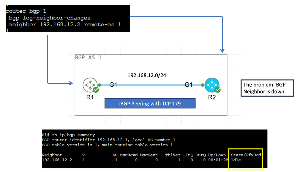
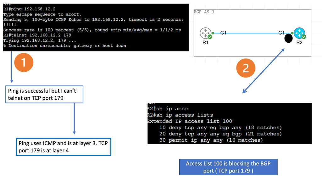
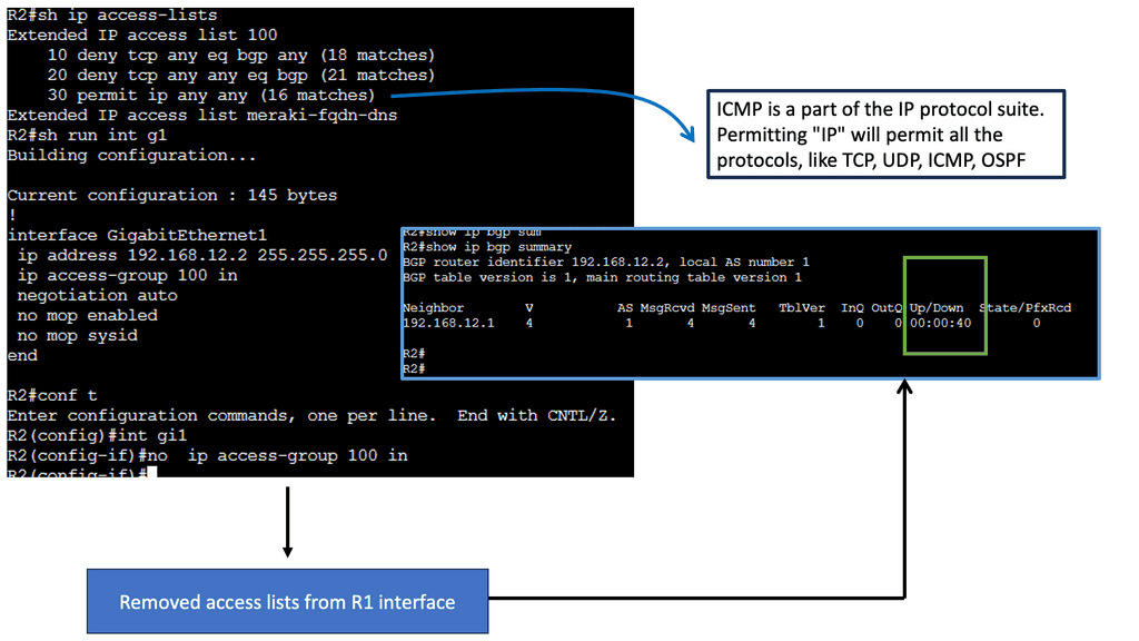
## The Role of TCP Port 179
BGP operates over Transmission Control Protocol (TCP), specifically utilizing port 179. This choice ensures reliable delivery of routing information, as TCP guarantees data integrity and order. The use of TCP port 179 is significant because it establishes a stable and consistent communication channel between peers, allowing them to exchange routing tables and updates efficiently. This setup is crucial for maintaining the dynamic nature of the internet’s routing tables as networks grow and change.
## Types of BGP Peering: IBGP vs. EBGP
BGP peering can be categorized into two primary types: Internal BGP (IBGP) and External BGP (EBGP). IBGP occurs within a single autonomous system, facilitating the distribution of routing information internally. It ensures that routers within the same AS are aware of the best paths to reach various network destinations. On the other hand, EBGP is used between different autonomous systems, enabling the exchange of routing information across organizational boundaries. Understanding the differences between these two is essential for network engineers to optimize routing policies and ensure efficient data flow.
## Peering Policies and Agreements
The establishment of BGP peering requires careful consideration of peering policies and agreements. Network operators must decide on the terms of peering, which can include settlement-free peering, paid peering, or transit arrangements. These policies dictate how traffic is exchanged, how costs are shared, and how disputes are resolved. Crafting effective peering agreements is vital for maintaining good relationships between different network operators and ensuring stable connectivity.
BGP Key Considerations:
Enhanced Scalability: BGP’s ability to handle large-scale networks makes it an ideal choice for data centers experiencing exponential growth. With BGP, data centers can handle thousands of routes and efficiently distribute traffic across multiple paths.
Increased Resilience: Data centers require high availability and fault tolerance. BGP’s robustness and ability to detect network failures make it valuable. BGP minimizes downtime and enhances network resilience by quickly rerouting traffic to alternative paths.
Improved Traffic Engineering: BGP’s advanced features enable precise control over traffic flow within the data center. Network administrators can implement traffic engineering policies, load balancing, and prioritization, ensuring optimal resource utilization.
Technologies: BGP-only Data Centers
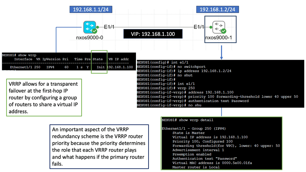
Nexus 9000 Series VRRP
Nexus 9000 Series VRRP is a high-performance routing protocol designed to provide redundancy and fault tolerance in network environments. It allows for the automatic failover of routers in case of a failure, ensuring seamless connectivity and minimizing downtime. By utilizing VRRP, businesses can achieve enhanced network availability and reliability.
The Nexus 9000 Series VRRP has many features that make it a compelling choice for network administrators. Firstly, it supports IPv4 and IPv6, ensuring compatibility with modern network architectures. Additionally, it offers load-balancing capabilities, distributing traffic efficiently across multiple routers. This not only improves overall network performance but also optimizes resource utilization. Furthermore, Nexus 9000 Series VRRP provides simplified management and configuration options, streamlining the deployment process and reducing administrative overhead.
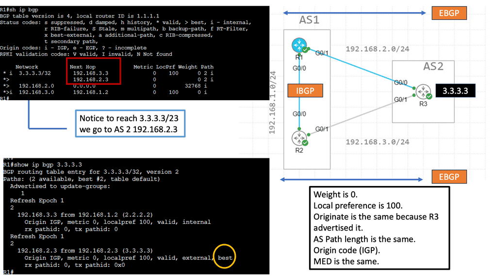
Example: Prefer EBGP over iBGP
Understanding BGP Path Attributes
BGP path attributes are pieces of information associated with each BGP route. They carry valuable details such as the route’s origin, the path the route has taken, and various other characteristics. These attributes are crucial in determining the best path for routing packets.
Network engineers commonly encounter several BGP path attributes. Some notable ones include AS Path, Next Hop, Local Preference, and MED (Multi-Exit Discriminator). Each attribute serves a specific purpose and aids in the efficient functioning of BGP.
Implementing BGP in Data Centers
Before diving into the implementation details, it is essential to grasp the fundamentals of BGP. BGP is an exterior gateway protocol that enables the exchange of routing information between different autonomous systems (AS).
It leverages a path-vector algorithm to make routing decisions based on various attributes, including AS path, next-hop, and network policies. This dynamic nature of BGP makes it ideal for data centers that require dynamic and adaptable routing solutions.
Implementing BGP in data centers brings forth a myriad of advantages. Firstly, BGP facilitates load balancing and traffic engineering by intelligently distributing traffic across multiple paths, optimizing network utilization and reducing congestion.
Additionally, BGP offers enhanced fault tolerance and resiliency through its ability to quickly adapt to network changes and reroute traffic. Moreover, BGP’s support for policy-based routing allows data centers to enforce granular traffic control and prioritize certain types of traffic based on defined policies.
**Challenges and Considerations**
While BGP offers numerous benefits, its implementation in data centers also poses certain challenges. One of the key considerations is the complexity associated with configuring and managing BGP. Data center administrators need to have a thorough understanding of BGP principles and carefully design their BGP policies to ensure optimal performance.
Furthermore, the dynamic nature of BGP can lead to route convergence issues, which require proactive monitoring and troubleshooting. It is crucial to address these challenges through proper planning, documentation, and ongoing network monitoring.
To ensure a successful BGP implementation in data centers, adhering to best practices is essential. Firstly, it is recommended to design a robust and scalable network architecture that accounts for future growth and increased traffic demands.
Additionally, implementing route reflectors or BGP confederations can help mitigate the complexity associated with full mesh connectivity. Regularly reviewing and optimizing BGP configurations, as well as implementing route filters and prefix limits, are also crucial steps to maintain a stable and secure BGP environment.
Example: BGP Multipath
Understanding BGP Multipath
BGP Multipath, short for Border Gateway Protocol Multipath, enables the simultaneous installation of multiple paths at an equal cost for a given destination network. This allows for load sharing across these paths, distributing traffic and mitigating congestion. By harnessing this capability, network administrators can maximize their resources, enhance network performance, and better utilize network links.
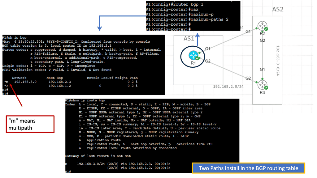
Implementing BGP Multipath offers several advantages.
a) First, it enhances network resiliency and fault tolerance by providing redundancy. In case one path fails, traffic can seamlessly reroute through an alternative path, minimizing downtime and ensuring uninterrupted connectivity.
b) Second, BGP Multipath enables better bandwidth utilization, as traffic can be distributed evenly across multiple paths. This load-balancing mechanism optimizes network performance and reduces the risk of bottlenecks, resulting in a smoother and more efficient user experience.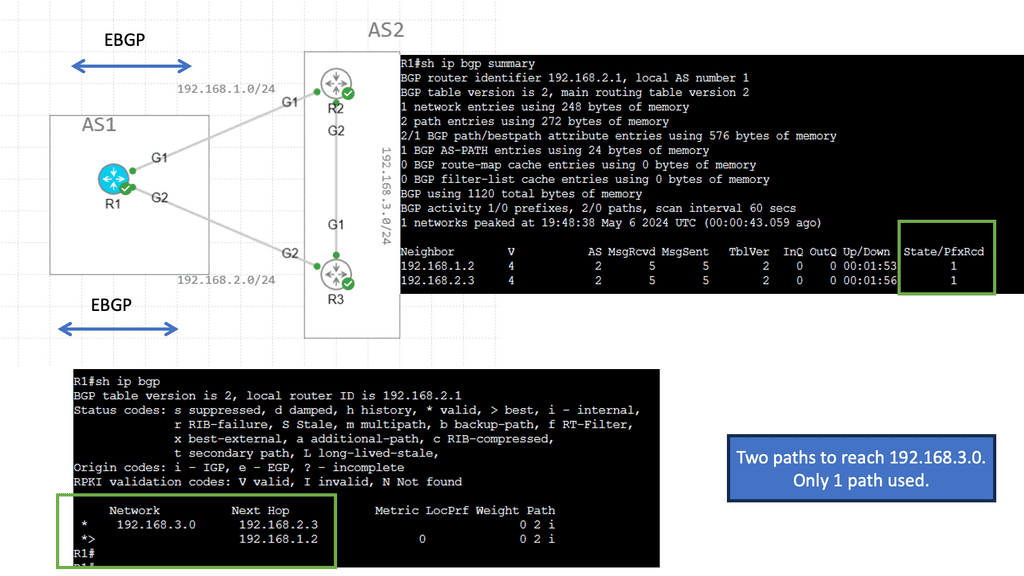
**BGP Data Center Key Points**
Hardware and Software Considerations: Suitable hardware and software support are essential for implementing BGP in data centers. Data center switches and routers should be equipped with BGP capabilities, and the chosen software should provide robust BGP configuration options.
Designing BGP Topologies: Proper BGP topology design is crucial for optimizing network performance. Data center architects should consider factors such as route reflectors, peer groups, and the correct placement of BGP speakers to achieve efficient traffic distribution.
Configuring BGP Policies: BGP policies are vital in controlling route advertisements and influencing traffic flow. Administrators should carefully configure BGP policies to align with data center requirements, considering factors like path selection, filtering, and route manipulation.
BGP in the data center
Due to its versatility, BGP is notoriously complex. IPv4 and IPv6, as well as virtualization technologies like MPLS and VXLAN, are all supported by BGP peers. Therefore, BGP is known as a multiprotocol routing protocol. Complex routing policies can be applied because BGP exchanges routing information across administrative domains. As a result of these policies, BGP calculates the best path to reach destinations, announces routes, and specifies their attributes. BGP also supports Unequal-Cost Multipath (UCMP), though not all implementations do.
Example Technology: BGP Route Reflection
BGP route reflection is used in BGP networks to reduce the number of BGP peering sessions required when propagating routing information. Instead of forcing each BGP router to establish a full mesh of connections with every other router in the network, route reflection allows for a hierarchical structure where certain routers act as reflectors.
These reflectors receive routing updates from their clients and reflect them to other clients, effectively reducing the complexity and overhead of BGP peering.
Configuring BGP route reflection involves designating certain routers as route reflectors and configuring the appropriate BGP attributes. Route reflectors should be strategically placed within the network to ensure efficient distribution of routing information.
Determining route reflector clusters and client relationships is essential to establish the hierarchy effectively. Network administrators can optimize routing update flow by adequately configuring route reflectors and ensuring seamless communication between BGP speakers.
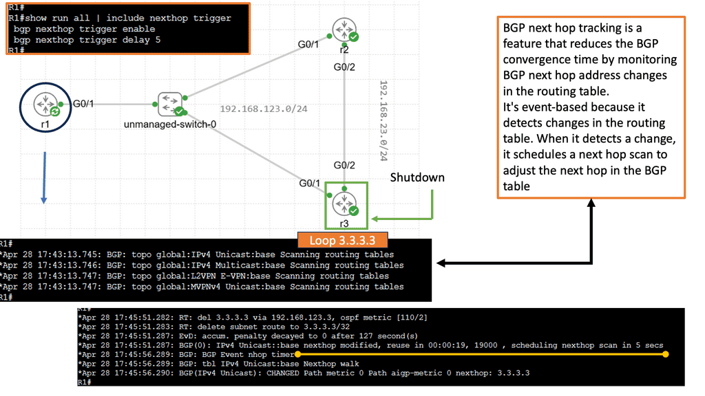
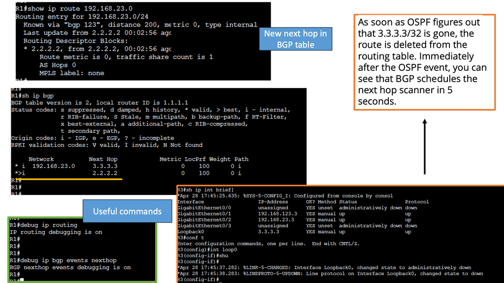
Example Technology: BGP Next hop tracking
Using BGP next-hop tracking, we can reduce BGP convergence time by monitoring changes in BGP next-hop addresses in the routing table. It is an event-based system because it detects changes in the routing table. When it detects a change, it schedules a next hop scan to adjust the next hop in the BGP table.
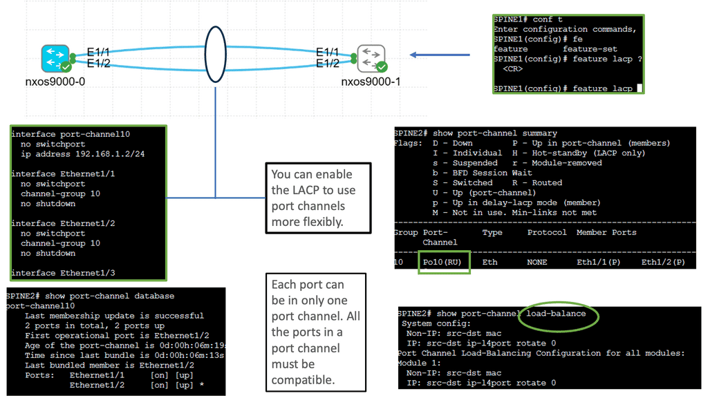
Understanding Port Channel on Nexus
Port Channel, also known as Link Aggregation, is a technique that allows multiple physical links to be combined into a single logical link. This aggregation enhances bandwidth capacity and redundancy by creating a virtual port channel interface. By effectively utilizing multiple links, the Cisco Nexus 9000 Port Channel delivers superior performance and fault tolerance.
Configuring a Cisco Nexus 9000 Port Channel is straightforward and requires a few essential steps. First, ensure that the physical interfaces participating in the Port Channel are correctly connected. Then, create a Port Channel interface and assign a unique channel-group number. Next, assign the physical interfaces to the Port Channel using the channel-group command. Finally, the Port Channel settings, such as the load balancing algorithm and interface mode, are configured.
Certain best practices should be followed to optimize the performance of the Cisco Nexus 9000 Port Channel. First, select the appropriate load-balancing algorithm based on your network requirements—options like source-destination IP hash or source-destination MAC hash offer effective load distribution. Second, ensure that the physical interfaces connected to the Port Channel have consistent configuration settings. A mismatch can lead to connectivity issues and reduced performance.
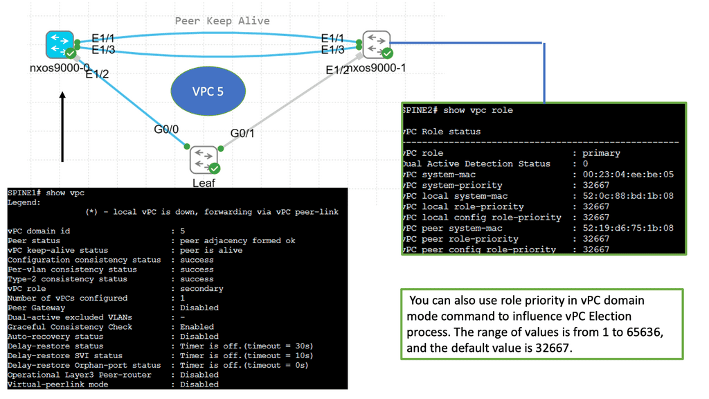
Key Data Center Technology: Understanding VPC
VPC enables the creation of a virtual link between two physical switches, allowing them to operate as a single logical entity. This eliminates the traditional challenges associated with Spanning Tree Protocol (STP) and enhances network resiliency and bandwidth utilization. The Cisco Nexus 9000 series switches provide robust support for VPC, making them an ideal choice for modern data centers.
The Cisco Nexus 9000 series switches provide comprehensive support for VPC deployment. The process involves establishing a peer link between the switches, configuring VPC domain parameters, and creating port channels. Additionally, VPC can be seamlessly integrated with advanced features such as Virtual Extensible LAN (VXLAN) and fabric automation, further enhancing network capabilities.

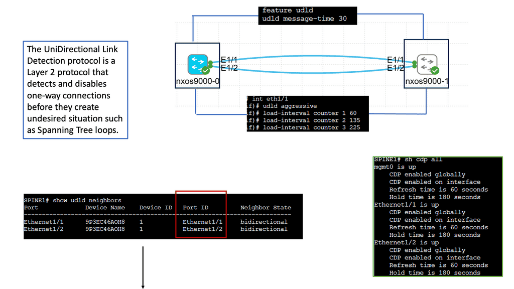
Understanding Unidirectional Links
Unidirectional links occur when data traffic can flow in one direction but not in the opposite direction. This can happen for various reasons, such as faulty cables, misconfigurations, or hardware failures. Identifying and resolving these unidirectional links is crucial to maintaining a healthy network environment.
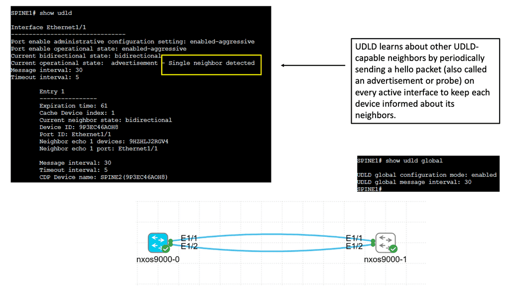
UDLD is a Cisco proprietary protocol designed to detect and mitigate unidirectional links. It operates at the data link layer, exchanging heartbeat messages between neighboring devices. By comparing the received and expected heartbeat messages, UDLD can identify any discrepancies and take appropriate actions.
– Network Resiliency: UDLD helps identify unidirectional links promptly, allowing network administrators to proactively rectify the issues. This leads to improved network resiliency and reduced downtime.
– Data Integrity: Unidirectional links can result in data loss or corruption. With UDLD in place, potential data integrity issues can be identified and addressed, ensuring reliable data transmission.
– Simplified Troubleshooting: UDLD provides clear alerts and notifications when unidirectional links are detected, making troubleshooting faster and more efficient. This helps network administrators pinpoint the issue’s root cause without wasting time on unnecessary investigations.
The Role of EVPN
BGP, traditionally used for routing between autonomous systems on the internet, has found its way into data centers due to its scalability and flexibility. When combined with EVPN, BGP becomes a powerful tool for creating virtualized and highly efficient networks within data centers. EVPN extends BGP to support Ethernet-based services, allowing for seamless connectivity and advanced features.
The adoption of BGP and EVPN in data centers brings numerous advantages. Firstly, it provides efficient and scalable multipath forwarding, allowing for better utilization of network resources and load balancing.
Secondly, BGP and EVPN enable seamless mobility of virtual machines (VMs) within and across data centers, reducing downtime and enhancing flexibility. Additionally, these technologies offer simplified network management, increased security, and support for advanced network services.
Use Cases of BGP and EVPN in Data Centers
BGP and EVPN have found extensive use in modern data centers across various industries. One prominent use case is in the deployment of large-scale virtualized infrastructures. By leveraging BGP and EVPN, data center operators can create robust and flexible networks that can handle the demands of virtualized environments. Another use case is in the implementation of data center interconnects, allowing for seamless communication and workload mobility between geographically dispersed data centers.
As data centers continue to evolve, the role of BGP and EVPN is expected to grow even further. Future trends include the adoption of BGP and EVPN in hyperscale data centers, where scalability and efficiency are paramount. Moreover, the integration of BGP and EVPN with emerging technologies such as software-defined networking (SDN) and network function virtualization (NFV) holds great promise for the future of data center networking.
In network virtualization solutions such as EVPN, OSPF is sometimes used instead of BGP to build the underlay network. Many proprietary or open-source routing stacks outside of FRR do not support using a single BGP session with a neighbor to do both overlays and underlays.
Service providers traditionally configure underlay networks using IGPs and overlay networks using BGP. OSPF is often used by network administrators who are familiar with this model. Because most VXLAN networks use an IPv4 underlay exclusively, they use OSPFv2 rather than OSPFv3.
Example: Use Case Cumulus
The challenges of designing a proper layer-3 data center surface at the access layer. Dual-connected servers terminating on separate Top-of-Rack (ToR) switches cannot have more than one IP address—a limitation results in VLAN sprawl, unnecessary ToR inter-switch links, and uplink broadcast domain sharing.
Cumulus Networks devised a clever solution entailing the redistribution of Address Resolution Protocol (ARP), avoiding Multi-Chassis Link Aggregation (MLAG) designs, and allowing pure Layer-3 data center networks. Layer 2 was not built with security in mind. Introducing a Layer-3-only data center eliminates any Layer 2 security problems.
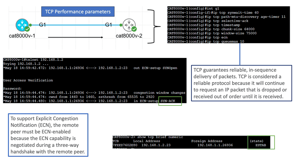
Layer 3 Data Center Performance
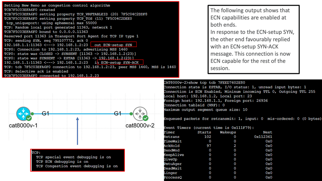
Understanding TCP Congestion Control
TCP Congestion Control is a crucial aspect of TCP performance parameters. It regulates the amount of data that can be sent before receiving acknowledgments. By adjusting the congestion window size and the slow-start threshold, TCP dynamically adapts to the network conditions, preventing congestion and ensuring smooth data transmission.
– Window Size and Throughput: The TCP window size determines the amount of unacknowledged data sent before receiving an acknowledgment. A larger window size allows for increased throughput, as more data can be transmitted without waiting for acknowledgments. However, a balance must be struck to avoid overwhelming the network and inducing packet loss.
– Maximum Segment Size (MSS): The Maximum Segment Size (MSS) refers to the most significant amount of data that can be transmitted in a single TCP segment. It is an important parameter that affects TCP performance. By optimizing the MSS, we can minimize packet fragmentation and maximize network efficiency.
– Timeouts and Retransmission: Timeouts and retransmission mechanisms are crucial in TCP performance. When a packet is not acknowledged within a certain time limit, TCP retransmits the packet. Properly tuning the timeout value is essential for maintaining a balance between responsiveness and avoiding unnecessary retransmissions.
What is TCP MSS?
TCP MSS, or Maximum Segment Size, refers to the largest amount of data that can be sent in a single TCP segment. It plays a vital role in determining the efficiency and reliability of data transmission across networks. Understanding how TCP MSS is calculated and utilized is essential for network administrators and engineers.
The proper configuration of TCP MSS can significantly impact network performance. By adjusting the MSS value, data transfer can be optimized, and potential issues such as packet fragmentation and reassembly can be mitigated. This section will explore the importance of TCP MSS in ensuring smooth and efficient data transmission.
Various factors, such as network technologies, link types, and devices involved, can influence the determination of TCP MSS. Considering these factors when configuring TCP MSS is crucial to prevent performance degradation and ensure compatibility across different network environments. This section will discuss the key aspects that need to be considered.
Adhering to best practices for TCP MSS configuration is essential to maximizing network performance. This section will provide practical tips and guidelines for network administrators to optimize TCP MSS settings, including consideration of MTU (Maximum Transmission Unit) and PMTUD (Path MTU Discovery) mechanisms.

Data Center Overlay Technologies
Example: VXLAN Flood and Learn
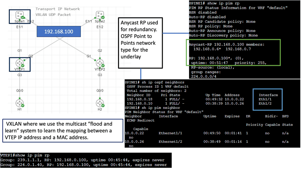
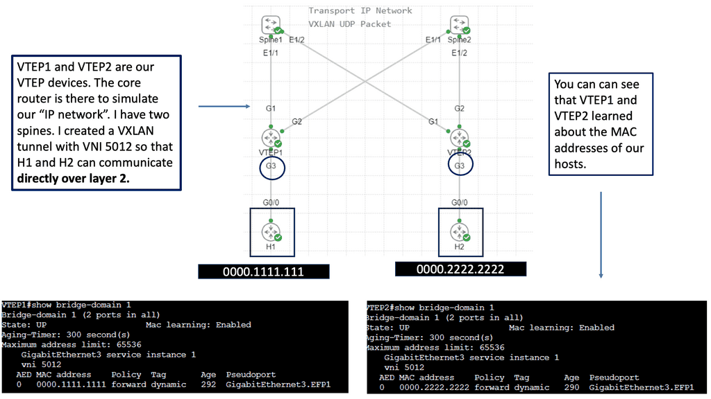
The Flood and Learn Mechanism
The Flood and Learn mechanism within VXLAN allows for dynamic learning of MAC addresses in a VXLAN segment. The destination MAC address is unknown when a packet arrives at a VXLAN Tunnel Endpoint (VTEP). The packet is then flooded across all VTEPs within the VXLAN segment, and the receiving VTEPs learn the MAC address associations. As a result, subsequent packets destined for the same MAC address can be forwarded directly, optimizing network efficiency.
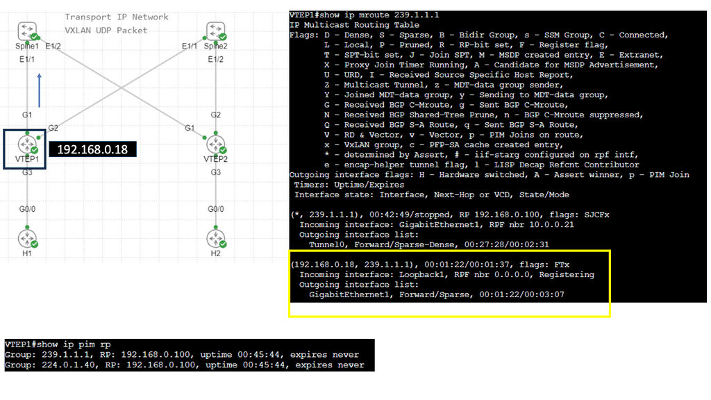
Multicast plays a crucial role in VXLAN Flood and Learn. Using multicast groups, VXLAN-enabled switches can efficiently distribute broadcast, unknown unicast, and multicast (BUM) traffic across the network. Multicast allows for optimized traffic replication, reducing unnecessary network congestion and improving overall performance.
Implementing VXLAN Flood and Learn with Multicast requires careful planning and configuration. Key aspects to consider include proper multicast group selection, network segmentation, VTEP configuration, and integration with existing network infrastructure. A well-designed implementation ensures optimal performance and scalability.
VXLAN Flood and Learn with Multicast finds its application in various scenarios. Data centers with virtualized environments benefit from the efficient forwarding of traffic, reducing network load and improving overall performance. VXLAN Flood and Learn with Multicast is instrumental in environments where workload mobility and scalability are critical, such as cloud service providers and multi-tenant architectures.

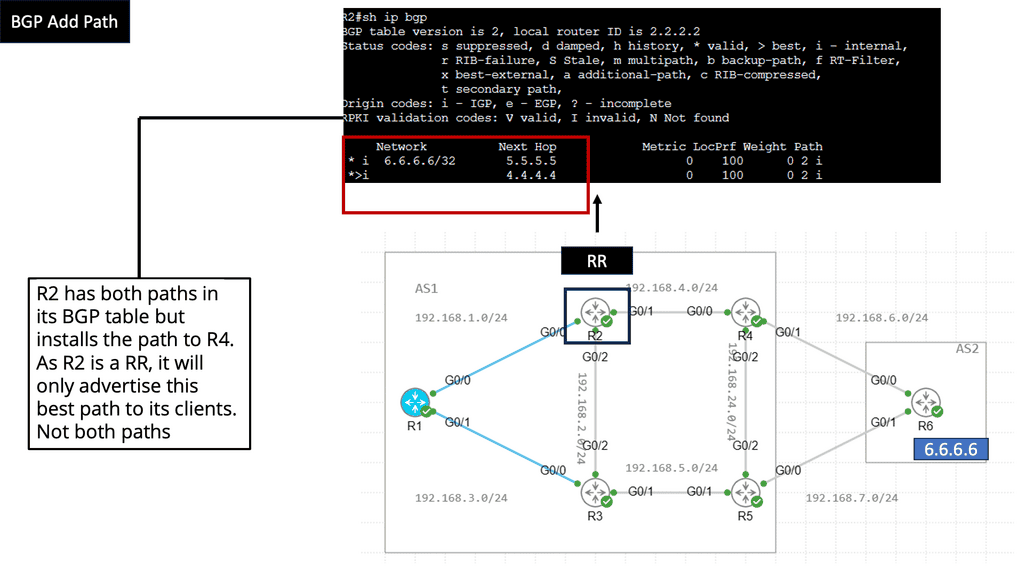
BGP Add Path
Understanding BGP Add Path
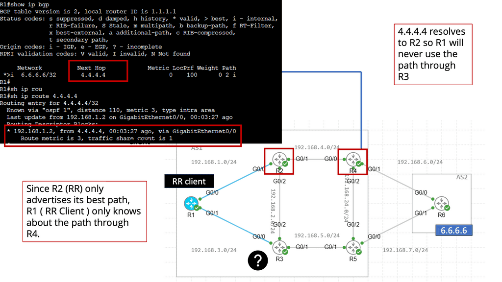
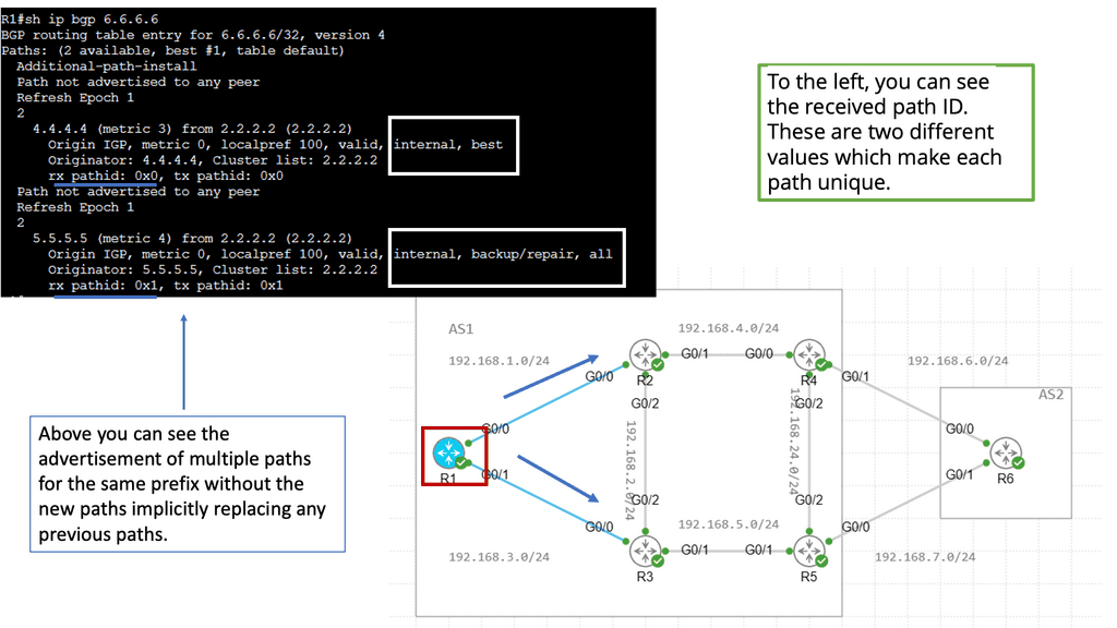
At its core, BGP Add Path enhances the traditional BGP route selection process by allowing the advertisement of multiple paths for a particular destination prefix. This means that instead of selecting a single best forward path, BGP routers can now keep numerous paths in their routing tables, each with its attributes. This opens up a new realm of possibilities for network engineers to optimize their networks and improve overall performance.
The BGP Add Path feature offers several benefits. First, it enhances network resilience by providing redundant paths for traffic to reach its destination. In case of link failures or congested paths, alternative routes can be quickly utilized, ensuring minimal disruption to network services. Additionally, it allows for improved load balancing across multiple paths, maximizing bandwidth utilization and optimizing network resources.
Traffic Engineering & Policy Routing
Furthermore, BGP Add Path is precious when traffic engineering and policy-based routing are crucial. Network administrators can now manipulate the selection of paths based on specific criteria such as latency, cost, or path preference. This level of granular control empowers them to fine-tune their networks according to their unique requirements.
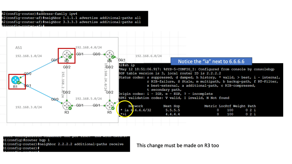
Network devices must support the feature to leverage the power of BGP Add Path. Fortunately, major networking vendors have embraced this enhancement and incorporated it into their products. Implementation typically involves enabling the feature on BGP routers and configuring the desired behavior for path selection and advertisement. Network operators must also ensure their network infrastructure can handle the additional memory requirements of storing multiple paths.
You may find the following helpful post for pre-information:
Understanding VPC Networking
VPC networking provides a virtual network environment for your Google Cloud resources. It allows you to logically isolate your resources, control network traffic, and establish connectivity with on-premises networks or other cloud providers. With VPC networking, you have complete control over IP addressing, subnets, firewall rules, and routing.

Google Cloud’s VPC networking offers a range of powerful features that enhance network management and security. These include custom IP ranges, multiple subnets, network peering, and VPN connectivity. By leveraging these features, you can design a flexible and secure network architecture that meets your specific requirements.
To make the most out of VPC networking in Google Cloud, it is essential to follow best practices. Start by carefully planning your IP address ranges and subnet design to avoid potential conflicts or overlaps. Implement granular firewall rules to control inbound and outbound traffic effectively. Utilize network peering to establish efficient communication between VPC networks. Regularly monitor and optimize your network for performance and cost efficiency.


Understanding VPC Peering
VPC Peering is a technology that allows the connection of Virtual Private Clouds (VPCs) within the same cloud provider or across multiple cloud providers. It enables secure and private communication between VPCs, facilitating data exchange and resources. Whether using Google Cloud or any other cloud platform, VPC Peering is a powerful tool that enhances network connectivity.

VPC Peering offers organizations a plethora of benefits. First, it simplifies network architecture by eliminating the need for complex VPN configurations or public IP addresses. Second, it provides low-latency and high-bandwidth connections, ensuring efficient data transfer between VPCs. Third, it enables organizations to create a unified network infrastructure, facilitating easier management and resource sharing.

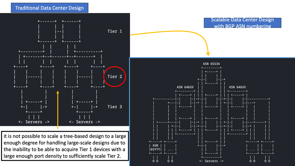
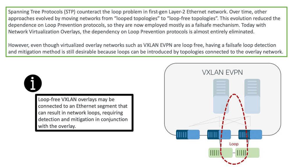
**Concepts of traditional three-tier design**
The classic data center uses a three-tier architecture, segmenting servers into pods. The architecture consists of core routers, aggregation routers, and access switches to which the endpoints are connected. Spanning Tree Protocol (STP) is used between the aggregation routers and access switches to build a loop-free topology for the Layer 2 part of the network. STP is simple and a plug-and-play technology requiring little configuration.
VLANs are extended within each pod, and servers can move freely within a pod without the need to change IP addresses and default gateway configurations. However, the downside of Spanning Tree Protocol is that it cannot use parallel forwarding paths and permanently blocks redundant paths in a VLAN.
A key point: Are we using the “right” layer 2 protocol?
Layer 1 is the easy layer. It defines an encoding scheme needed to pass ones and zeros between devices. Things get more interesting at Layer 2, where adjacent devices exchange frames (layer 2 packets) for reachability. Layer-2 or MAC addresses are commonly used at Layer 2 but are not always needed. Their need arises when more than two devices are attached to the same physical network.
Imagine a device receiving a stream of bits. Does it matter if Ethernet, native IP, or CLNS/CLNP comes in the “second” layer? First, we should ask ourselves whether we use the “right” layer 2 protocol.
Concept of VXLAN
To overcome the issues of Spanning Tree, we have VXLAN. VXLAN is an encapsulation protocol used to create virtual networks over physical networks. Cisco and VMware developed it, and it was first published in 2011. VXLAN provides a layer 2 overlay on a layer 3 network, allowing traffic separation between different virtualized networks.
This is useful for cloud-based applications and virtualized networks in corporate environments. VXLAN works by encapsulating an Ethernet frame within an IP packet and then tunneling it across the network. This allows more extensive virtual networks to be created over the same physical infrastructure.
Additionally, VXLAN provides a more efficient routing method, eliminating the need to use multiple VLANs. It also separates traffic between multiple virtualized networks, providing greater security and control. VXLAN also supports multicast traffic, allowing faster data broadcasts to various users. VXLAN is an important virtualization and cloud computing tool, providing a secure, efficient, and scalable means of creating virtual networks.
Multipath Route Forwarding
Many networks implement VLANs to support random IP address assignment and IP mobility. The switches perform layer-2 forwarding even though they might be capable of layer-3 IP forwarding. For example, they forward packets based on MAC addresses within a subnet, yet a layer-3 switch does not need Layer 2 information to route IPv4 or IPv6 packets.
Cumulus has gone one step further and made it possible to configure every server-to-ToR interface as a Layer 3 interface. Their design permits multipath default route forwarding, removing the need for ToR interconnects and common broadcast domain sharing of uplinks.
Layer-3 Data Center: Bonding Vs. ECMP
A typical server environment consists of a single server with two uplinks. For device and link redundancy, uplinks are bonded into a port channel and terminated on different ToR switches, forming an MLAG. As this is an MLAG design, the ToR switches need an inter-switch link. Therefore, you cannot bond server NICs to two separate ToR switches without creating an MLAG.
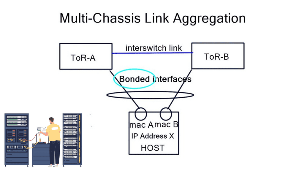
If you don’t want to use an MLAG, other Linux modes are available on hosts, such as “active | passive” and “active | passive on receive.” A 3rd mode is available but consists of a trick using other ARP replies for the neighbors. This forces both MAC addresses into your neighbors’ ARP cache, allowing both interfaces to receive. The “active | passive” model is popular as it offers predictable packet forwarding and easier troubleshooting.
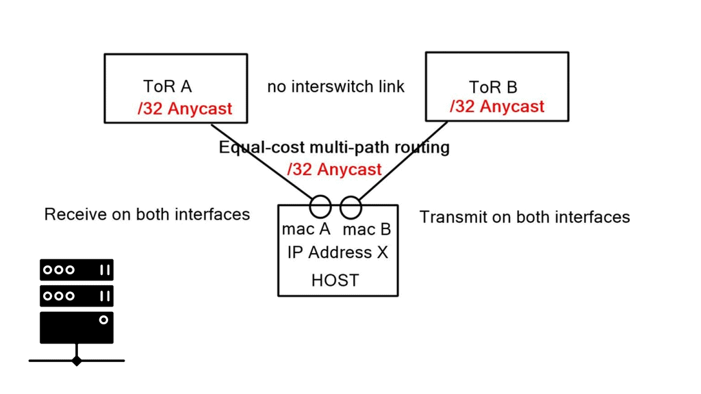
The “active | passive on receive” mode receives on one link but transmits on both. Usually, you can only receive on one interface, as that is in your neighbors’ ARP cache. To prevent MAC address flapping at the ToR switch, separate MAC addresses are transmitted. A switch receiving the same MAC address over two different interfaces will generate a MAC Address Flapping error.
We have a common problem in each bonding example: we can’t associate one IP address with two MAC addresses. These solutions also require ToR inter-switch links. The only way to get around this is to implement a pure layer-3 Equal-cost multipath routing (ECMP) solution between the host and ToR.
Pure layer-3 solution complexities
Firstly, we cannot have one IP address with two MAC addresses. To overcome this, we implement additional Linux features. First, Linux has the capability for an unnumbered interface, permitting the assignment of the same IP address to both interfaces, one IP address for two physical NICs. Next, we assign a /32 Anycast IP address to the host via a loopback address.
Secondly, the end hosts must send to a next-hop, not a shared subnet. Linux allows you to specify an attribute to the received default route, called “on-link.” This attribute tells end-hosts, “I might not be on a directly connected subnet to the next hop, but trust me, the next hop is on the other side of this link.” It forces hosts to send ARP requests regardless of common subnet assignment.
These techniques enable the assignment of the same IP address to both interfaces and permit forwarding a default route out of both interfaces. Each interface is on its broadcast domain. Subnets can span two ToRs without requiring bonding or an inter-switch link.
**Standard ARP processing still works**
Although the Layer 3 ToR switch doesn’t need Layer 2 information to route IP packets, the Linux end-host believes it has to deal with the traditional L2/L3 forwarding environment. As a result, the Layer 3 switch continues to reply to incoming ARP requests. The host will ARP for the ToR Anycast gateway (even though it’s not on the same subnet), and the ToR will respond with its MAC address. The host ARP table will only have one ARP entry because the default route points to a next-hop, not an interface.
Return traffic differs slightly depending on what the ToR advertises to the network. There are two modes: first, if the ToR advertises a /24 to the rest of the network, everything works fine until the server-to-ToR link fails. Then, it becomes a layer-2 problem; as you said, you could reach the subnet. This results in return traffic traversing an inter-switch ToR link to get back to the server.
But this goes against our previous design requirement to remove any ToR inter-switch links. Essentially, you need to opt for the second mode and advertise a /32 for each host back into the network.
Take the information learned in ARP, consider it a host routing protocol, and redistribute it into the data center protocol, i.e., redistribute ARP. The ARP table gets you the list of neighbors, and the redistribution pushes those entries into the routed fabric as /32 host routes. This allows you to redistribute only what /32 are active and present in ARP tables. It should be noted that this is not a default mode and is currently an experimental feature.
A Final Note: Layer 3 Data Centers
Layer 3 data centers offer several advantages over their Layer 2 counterparts. One of the main benefits is their ability to handle a larger volume of data traffic without compromising speed or performance. By utilizing advanced routing protocols, Layer 3 data centers can efficiently manage data packets, reducing latency and improving overall network performance. Additionally, these data centers provide enhanced security features, as they are capable of implementing more sophisticated access control measures and firewall protections.
When considering a transition to a Layer 3 data center, there are several factors to take into account. First, it’s essential to evaluate the existing network infrastructure and determine if it can support the advanced capabilities of a Layer 3 environment. Organizations should also consider the potential costs associated with upgrading hardware and software, as well as the training required for IT staff to effectively manage the new system. Additionally, businesses should assess their specific needs for scalability and flexibility to ensure that a Layer 3 data center aligns with their long-term strategic goals.
As technology continues to advance, the role of Layer 3 data centers is expected to grow even more significant. With the rise of cloud computing, Internet of Things (IoT) devices, and edge computing, the demand for efficient and reliable network routing will only increase. Layer 3 data centers are well-positioned to meet these demands, offering the necessary infrastructure to support the growing complexity of modern networks. Furthermore, advancements in artificial intelligence and machine learning are likely to enhance the capabilities of Layer 3 data centers, enabling even more sophisticated data management solutions.