Understanding Data Center Speed
– To optimize data center performance, it’s essential to understand the infrastructure that supports these complex systems. Data centers comprise servers, storage systems, networking equipment, and cooling systems, all working together to process and store vast amounts of data. By analyzing each component’s role and performance, operators can identify areas for improvement and implement strategies that enhance overall efficiency.
– Advanced monitoring tools are invaluable for optimizing data center performance. These tools provide real-time insights into various performance metrics, such as server utilization, temperature, and power usage. By leveraging these insights, data center operators can make informed decisions, anticipate potential issues, and ensure optimal performance. Proactive monitoring also helps in preventing downtime, which is critical for maintaining service reliability.
**Data Center Performance Considerations:**
1: – ) Data center speed refers to the rate at which data can be processed, transferred, and accessed within a data center infrastructure. It encompasses various aspects, including network speed, processing power, storage capabilities, and overall system performance. As technology advances, the demand for faster data center speeds grows exponentially.
2: – ) In today’s digital landscape, real-time applications such as video streaming, online gaming, and financial transactions require lightning-fast data center speeds. Processing and delivering data in real-time is essential for providing users with seamless experiences and reducing latency issues. Data centers with high-speed capabilities ensure smooth streaming, responsive gameplay, and swift financial transactions.
3: -) Scalability is a critical aspect of modern data center performance. As businesses grow and digital demands increase, data centers must be able to scale efficiently. Adopting modular infrastructure, utilizing virtualized environments, and investing in flexible networking solutions enable data centers to expand their capacity seamlessly. Scalable infrastructure ensures that data centers can handle increased workloads without compromising performance or reliability.
High-Speed Networking:
High-speed networking forms the backbone of data centers, enabling efficient communication between servers, storage systems, and end-users. Technologies like Ethernet, fiber optics, and high-speed interconnects facilitate rapid data transfer rates, minimizing bottlenecks and optimizing overall performance. By investing in advanced networking infrastructure, data centers can achieve remarkable speeds and meet the demands of today’s data-intensive applications.
Leaf and spine performance:
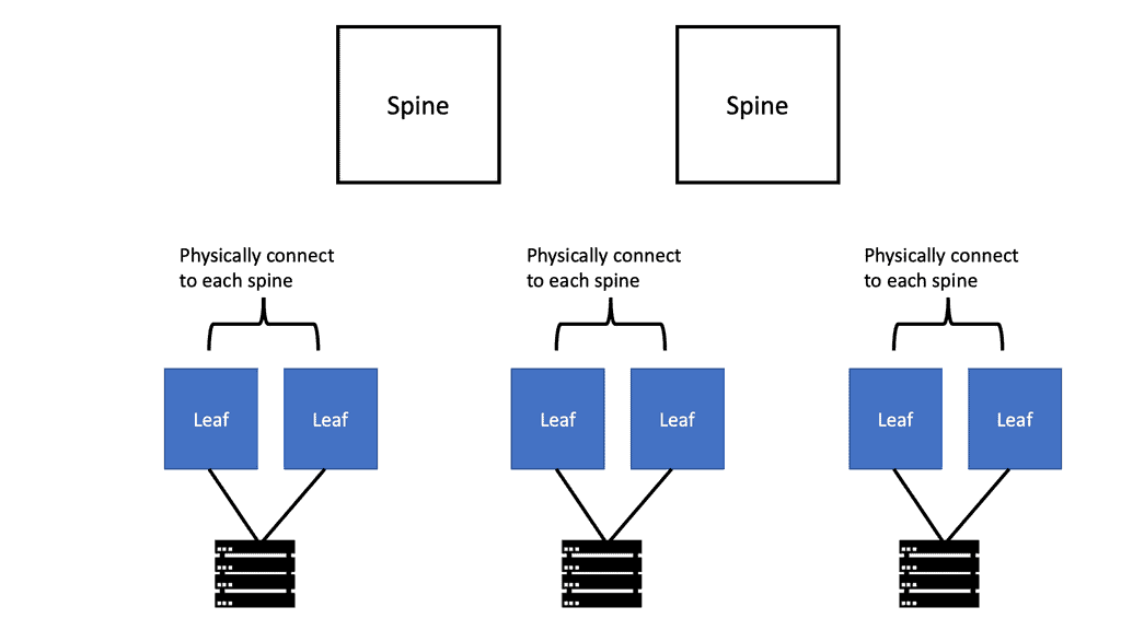
Leaf and spine architecture is a network design approach that provides high bandwidth, low latency, and seamless scalability. The leaf switches act as access switches, connecting end devices, while the spine switches form a non-blocking fabric for efficient data forwarding. This architectural design ensures consistent performance and minimizes network congestion.
Factors Influencing Leaf and Spine Performance
a) Bandwidth Management: Properly allocating and managing bandwidth among leaf and spine switches is vital to avoid bottlenecks. Link aggregation techniques, such as LACP (Link Aggregation Control Protocol), help with load balancing and redundancy.
b) Network Topology: The leaf and spine network topology design dramatically impacts performance. Ensuring equal interconnectivity between leaf and spine switches and maintaining appropriate spine switch redundancy enhances fault tolerance and overall performance.
c) Quality of Service (QoS): Implementing QoS mechanisms allows prioritization of critical traffic, ensuring smoother data flow and preventing congestion. Assigning appropriate QoS policies to different traffic types guarantees optimal leaf and spine performance.
**Performance Optimization Techniques**
a) Traffic Engineering: Effective traffic engineering techniques, like ECMP (Equal-Cost Multipath), evenly distribute traffic across multiple paths, maximizing link utilization and minimizing latency. Dynamic routing protocols, such as OSPF (Open Shortest Path First) or BGP (Border Gateway Protocol), can be utilized for efficient traffic flow.
b) Buffer Management: Proper buffer allocation and management at leaf and spine switches prevent packet drops and ensure smooth data transmission. Tuning buffer sizes based on traffic patterns and requirements significantly improves leaf and spine performance.
c) Monitoring and Analysis: Regular monitoring and analysis of leaf and spine network performance help identify potential bottlenecks and latency issues. Utilizing network monitoring tools and implementing proactive measures based on real-time insights can enhance overall performance.
Planning for Future Growth
One of the primary objectives of scaling a data center is to ensure it can handle future growth and increased workloads. This requires careful planning and forecasting. Organizations must analyze their projected data storage and processing needs, considering anticipated business growth, emerging technologies, and industry trends. By accurately predicting future demands, businesses can design a scalable data center that can adapt to changing requirements.
Example: Blockers to Performance
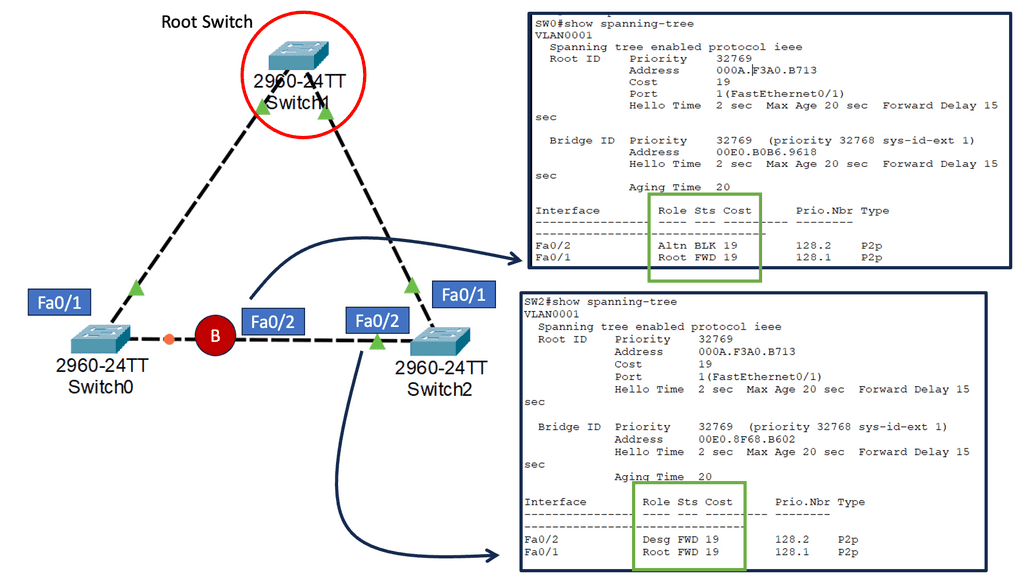
The Basics of Spanning Tree Protocol (STP)
A:- ) STP is a layer 2 network protocol that prevents loops in Ethernet networks. It creates a loop-free logical topology, ensuring a single active path between any network devices. We will discuss the critical components of STP, such as the root bridge, designated ports, and blocking ports. Understanding these elements is fundamental to comprehending the overall functionality of STP.
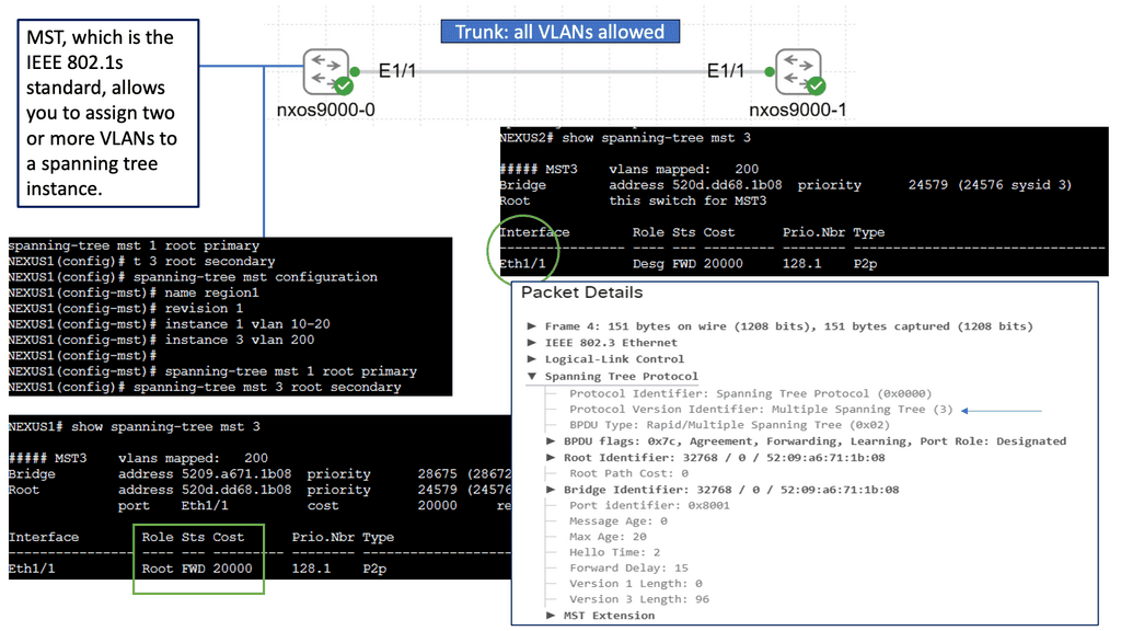
B:- ) While STP provides loop prevention and network redundancy, it has certain limitations. For instance, in large networks, STP can be inefficient due to the use of a single spanning tree for all VLANs. MST addresses this drawback by dividing the network into multiple spanning tree instances, each with its own set of VLANs. We will explore the motivations behind MST and how it overcomes the limitations of STP.
C:- ) Deploying STP MST in a network requires careful planning and configuration. We will discuss the steps for implementing MST, including creating MST regions, assigning VLANs to instances, and configuring the root bridges. Additionally, we will provide practical examples and best practices to ensure a successful MST deployment.
Gaining Visibility to Improve Performance
Understanding sFlow
sFlow is a network monitoring technology that provides real-time visibility into network traffic. It samples packets flowing through network devices, allowing administrators to analyze and optimize network performance. By capturing data at wire speed, sFlow offers granular insights into traffic patterns, application behavior, and potential bottlenecks.
Cisco NX-OS, a robust operating system for Cisco network switches, fully supports sFlow. Enabling sFlow on Cisco NX-OS can provide several key benefits. First, it facilitates proactive network monitoring by continuously collecting data on network flows. This real-time visibility enables administrators to swiftly identify and address performance issues, ensuring optimal network uptime.
sFlow for Troubleshooting & Analysis
sFlow on Cisco NX-OS equips network administrators with powerful troubleshooting and analysis capabilities. The technology provides detailed information on packet loss, latency, and congestion, allowing for swift identification and resolution of network anomalies. Additionally, sFlow offers insights into application-level performance, enabling administrators to optimize resource allocation and enhance user experience.
Capacity planning is a critical aspect of network management. By leveraging sFlow on Cisco NX-OS, organizations can accurately assess network utilization and plan for future growth. The detailed traffic statistics provided by sFlow enable administrators to make informed decisions about network upgrades, ensuring sufficient capacity to meet evolving demands.

Google Cloud Machine Types
### Understanding Google Cloud Machine Type Families
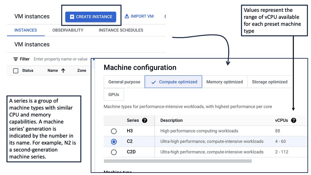
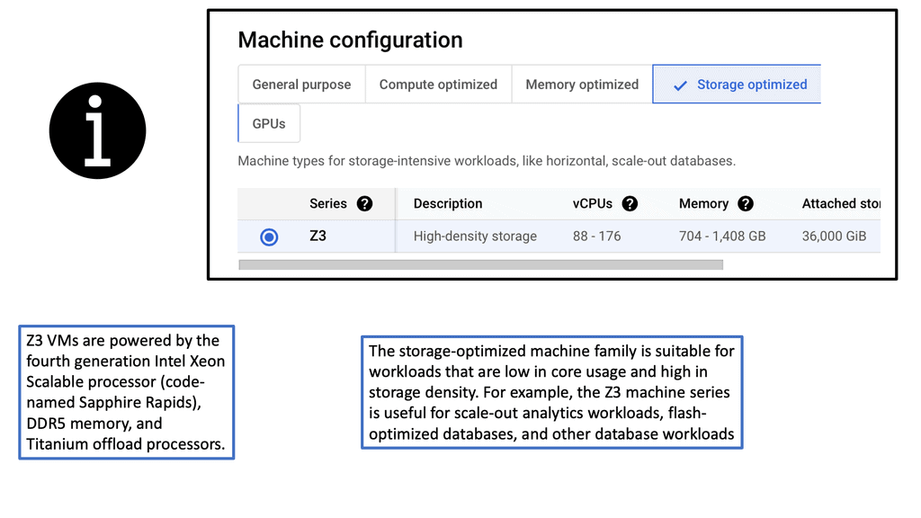
Machine type families in Google Cloud are organized into categories to cater to various workloads and performance needs. These categories include General-Purpose, Compute-Optimized, Memory-Optimized, and Accelerator-Optimized families. Each family is tailored with specific CPU, memory, and storage configurations to meet diverse computing requirements.
#### General-Purpose Machine Types
General-purpose machine types are versatile, offering a balanced mix of CPU and memory resources. They are ideal for a wide range of applications, including web servers, development environments, and small to medium-sized databases. These machine types are further classified into N1, N2, and E2 families, each providing different performance capabilities and cost structures.
#### Compute-Optimized Machine Types
For applications requiring high compute power, such as high-performance computing and gaming, Compute-Optimized machine types are the go-to choice. These machines are designed to deliver maximum CPU performance, making them perfect for tasks that demand significant processing power.
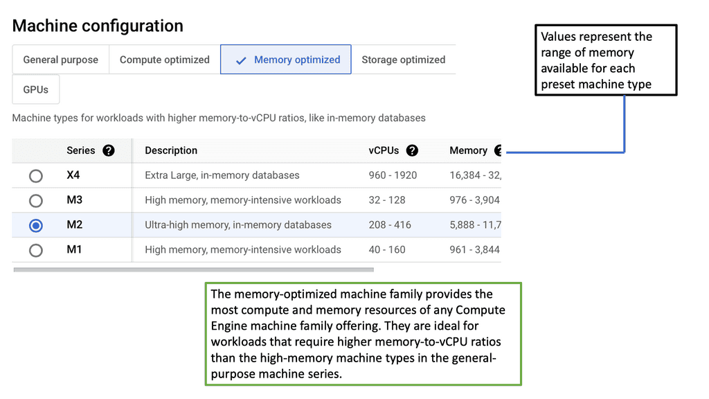
### Memory-Optimized and Accelerator-Optimized Machine Types
#### Memory-Optimized Machine Types
Memory-Optimized machine types provide a higher ratio of memory to CPU, making them suitable for applications that handle large datasets or require substantial memory resources. These include in-memory databases, real-time data analytics, and scientific simulations.
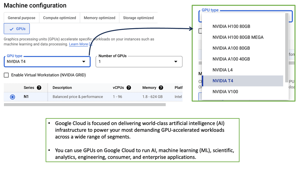
#### Accelerator-Optimized Machine Types
Accelerator-Optimized machine types are equipped with GPUs or TPUs, offering accelerated performance for machine learning and other computationally intensive tasks. These machines are specifically designed to handle workloads that benefit from parallel processing capabilities.
### Choosing the Right Machine Type for Your Needs
Selecting the appropriate machine type depends on your specific workload requirements. Consider factors such as the nature of your application, performance needs, and budget constraints. Google Cloud provides various tools and documentation to assist in the decision-making process, ensuring that you choose a machine type that aligns with your objectives.
Improving Performance with Managed Instance Groups
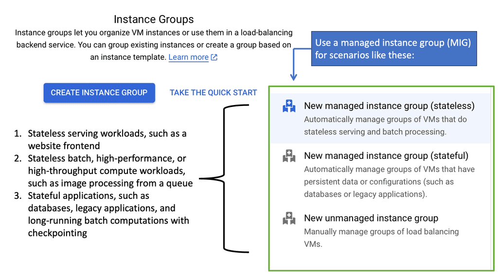
**Understanding the Basics of Managed Instance Groups**
Managed Instance Groups are collections of identical virtual machine (VM) instances, designed to provide high availability and scalability. By using MIGs, you can easily deploy and manage multiple instances without the need to handle each one individually. Google Cloud’s automation capabilities ensure that your applications remain highly available, by automatically distributing traffic across instances and replacing any that fail. This not only reduces the operational burden on IT teams but also ensures consistent performance across your cloud infrastructure.
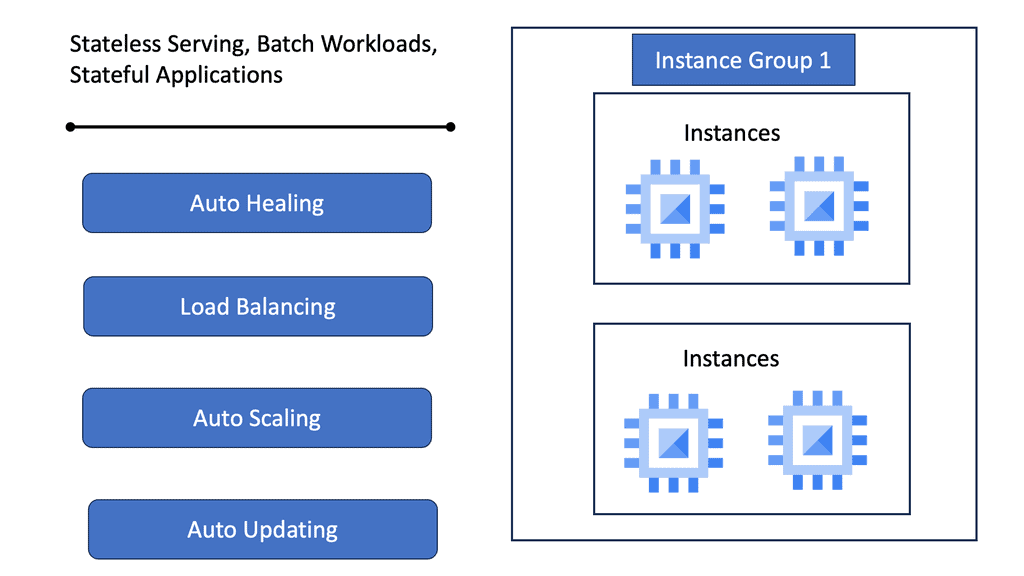
**Enhancing Data Center Performance with MIGs**
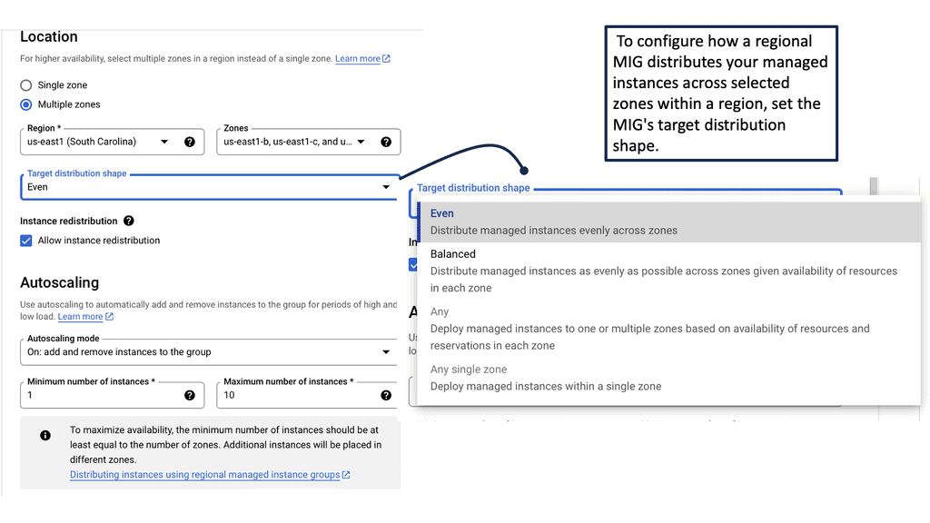
One of the key advantages of using Managed Instance Groups is the ability to dynamically scale your resources based on demand. With features like autoscaling, MIGs can automatically adjust the number of VM instances in response to traffic patterns, ensuring that your applications have the resources they need during peak times while minimizing costs during lulls. This flexibility is crucial for maintaining optimal data center performance, allowing businesses to deliver a seamless user experience without overspending on unnecessary resources.
—
**Leveraging Google Cloud’s Advanced Features**
Google Cloud provides several advanced features that complement Managed Instance Groups, further enhancing their benefits. For instance, with regional managed instance groups, you can spread your instances across multiple regions, increasing fault tolerance and improving redundancy. Additionally, Google Cloud’s load balancing capabilities work seamlessly with MIGs, ensuring efficient distribution of network traffic and reducing latency. By leveraging these features, organizations can build robust, high-performance cloud architectures that are resilient to failures and scalable to meet growing demands.
—
**Best Practices for Implementing Managed Instance Groups**
Successfully implementing Managed Instance Groups requires thoughtful planning and consideration of best practices. It’s essential to define clear scaling policies that align with your business needs and performance goals. Regularly monitor the performance of your MIGs to identify any bottlenecks or issues, and adjust your configurations as necessary. Additionally, take advantage of Google Cloud’s monitoring and logging tools to gain insights into your infrastructure’s performance and make data-driven decisions.
Performance & Health Checks
The Importance of Health Checks
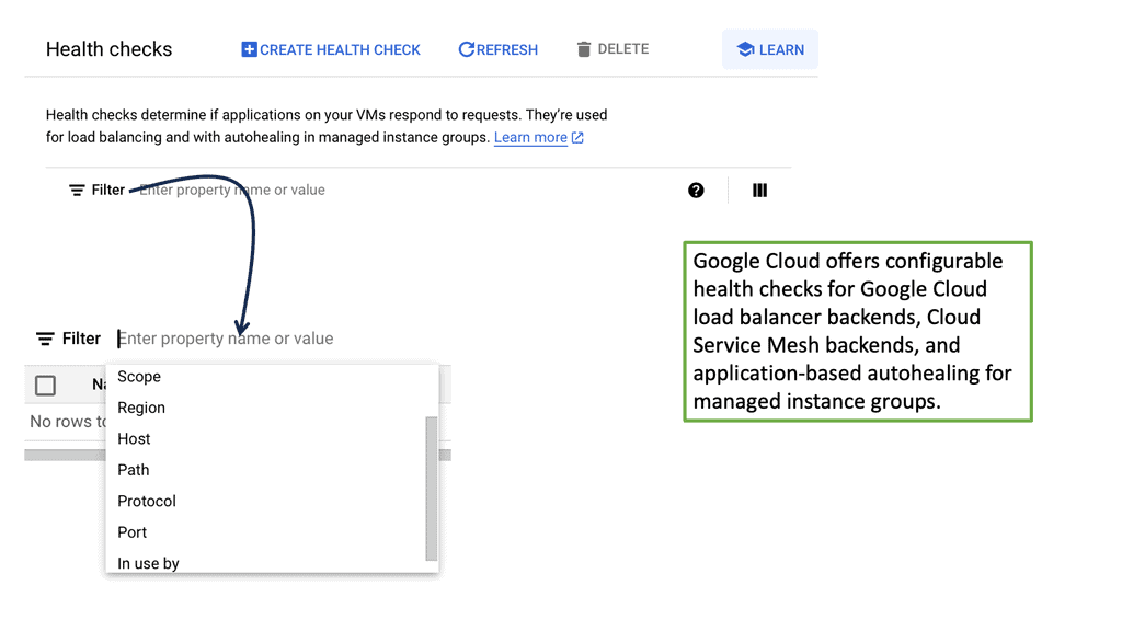
Health checks are automated processes that monitor the status of servers within a data center. They perform regular checks to determine whether a server is healthy and capable of handling requests. This is done by sending requests to the servers and analyzing the responses. If a server fails a health check, it is temporarily removed from the pool until it recovers, preventing downtime and maintaining optimal performance. In the realm of cloud computing, these checks are indispensable for maintaining seamless operations.
—
### Types of Health Checks in Google Cloud
Google Cloud offers a variety of health check options tailored to different needs. The primary types are HTTP(S), TCP, SSL, and gRPC health checks. Each type is designed to test different aspects of server health. For instance, HTTP(S) health checks are ideal for web services, as they test the response of the server to HTTP(S) requests. TCP health checks, on the other hand, are more suited for non-HTTP services, such as database servers. Choosing the right type of health check is crucial for accurately assessing server status and ensuring efficient load balancing.
—
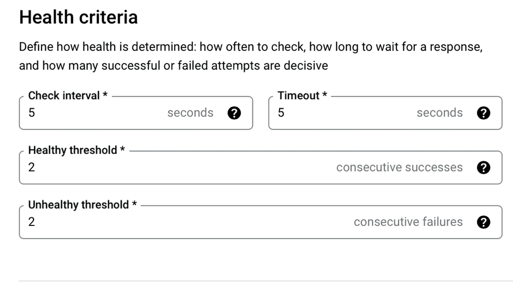
### Configuring Health Checks for Optimal Performance
To maximize data center performance, it’s essential to configure health checks properly. This involves setting parameters such as check intervals, timeout periods, and failure thresholds. For example, a shorter interval might catch failures more quickly, but it could also lead to false positives if set too aggressively. By fine-tuning these settings, you can ensure that your load balancer accurately reflects the health of your servers, leading to improved performance and reliability.

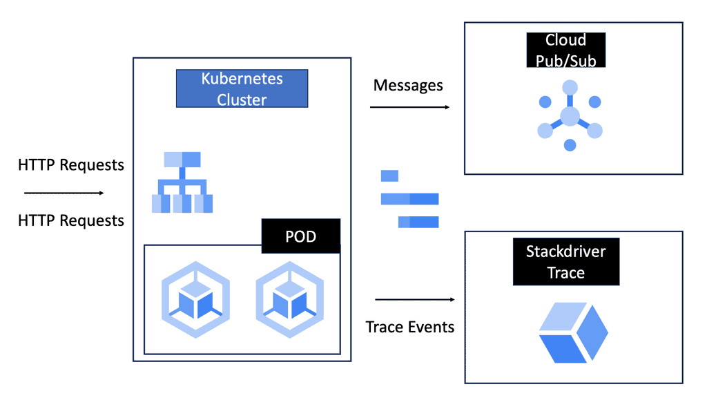
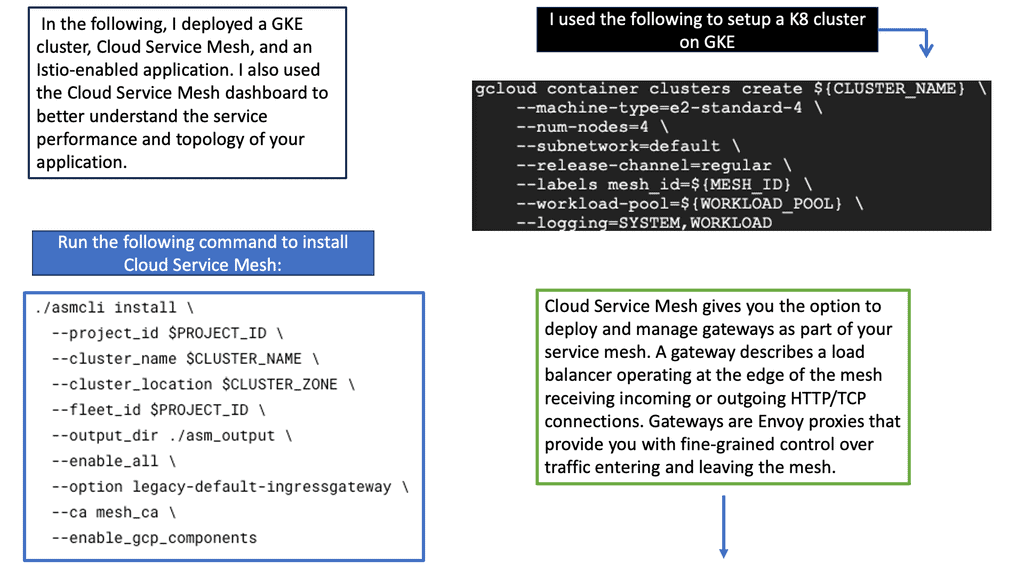
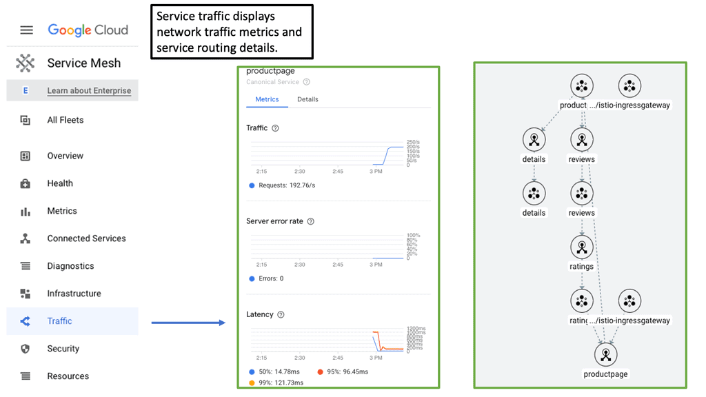
Performance with Cloud Service Mesh?
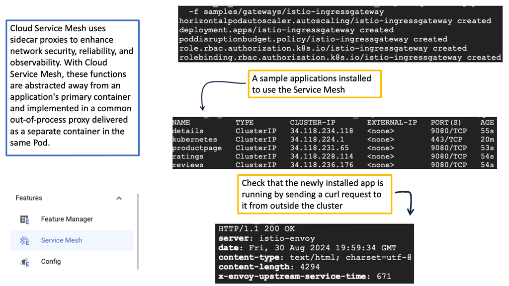
A cloud service mesh is a dedicated infrastructure layer designed to control, monitor, and secure the communication between microservices. It provides a unified way to manage service-to-service interactions, irrespective of the underlying platform or technology. By abstracting the complexity of service communication, a service mesh allows developers to focus on building features rather than worrying about operational concerns.
**1. Enhanced Observability**:
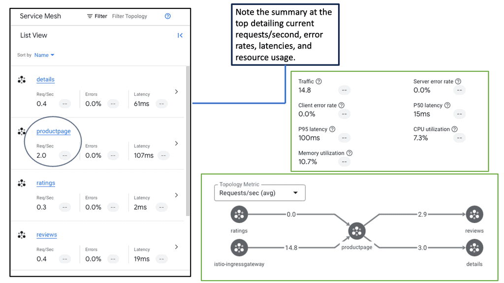
One of the primary advantages of implementing a cloud service mesh is the enhanced observability it provides. With built-in monitoring and tracing capabilities, a service mesh offers real-time insights into service performance. This heightened visibility helps in quickly diagnosing issues and optimizing the overall system.
**2. Improved Security**:
Security is a paramount concern in any data center environment. A cloud service mesh provides robust security features, such as mutual TLS authentication, to ensure secure communication between services. Additionally, it simplifies the implementation of security policies, reducing the risk of vulnerabilities and breaches.
**3. Simplified Traffic Management**:
Managing traffic flow between services can be complex, especially in large-scale environments. A service mesh simplifies traffic management through features like load balancing, traffic splitting, and circuit breaking. These capabilities help in optimizing resource utilization and improving application resilience.
### Impact on Data Center Performance
A well-implemented cloud service mesh can have a profound impact on data center performance. By streamlining service communication and reducing the overhead associated with managing microservices, a service mesh enhances the efficiency of the entire system. This leads to faster response times, reduced latency, and improved overall performance. Furthermore, the ability to quickly identify and resolve issues minimizes downtime, ensuring higher availability and reliability of services.
Google Cloud Performance Network Tiers
Understanding Network Tiers
Network tiers, in simple terms, refer to different levels of network service quality and performance. Google Cloud offers multiple network tiers, each tailored to meet specific requirements. The primary tiers include Standard Tier, Premium Tier, and the recently introduced Tiered Network Service.
The Standard Tier is the default network service level that offers a balance between performance and cost-efficiency. It provides reliable connectivity, making it suitable for a wide range of applications and workloads. By leveraging the Standard Tier, businesses can optimize their network spend without compromising on reliability.
For organizations that prioritize high-performance networking, the Premium Tier delivers unparalleled speed, low latency, and enhanced reliability. It leverages Google’s global network infrastructure, ensuring optimal connectivity and improved user experience. By adopting the Premium Tier, businesses can unlock the full potential of their network infrastructure and provide seamless services to their customers.


Improving Performance with CDNs
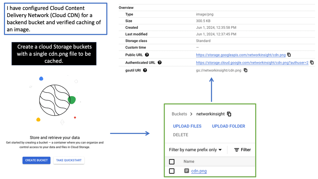
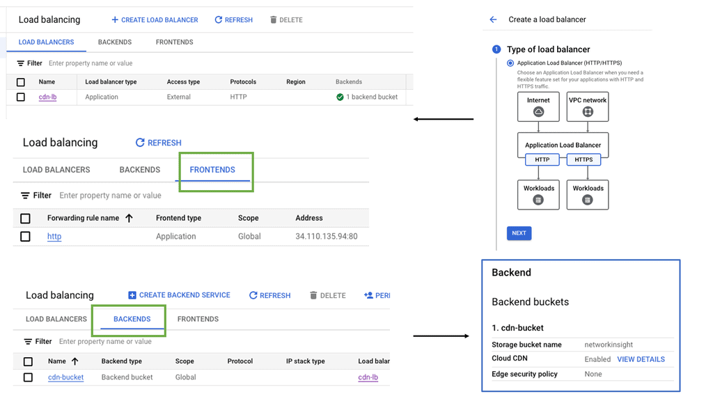
Understanding Cloud CDN
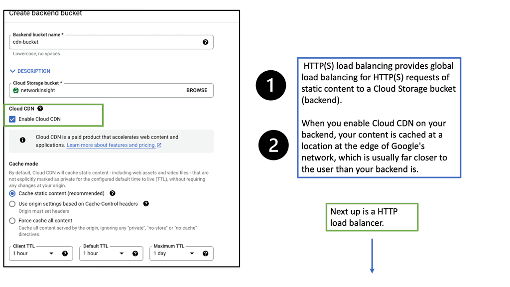
Cloud CDN is a global, low-latency content delivery network offered by Google Cloud. It caches and delivers content from locations closer to users, reducing latency and improving website performance. By distributing content across a global network of edge locations, Cloud CDN ensures faster delivery and reduced bandwidth costs.
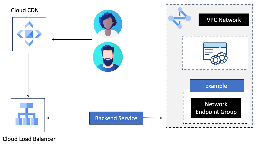
a) Improved Page Load Times: By caching content at the edge, Cloud CDN reduces the distance between users and website resources, resulting in faster page load times and enhanced user experiences.
b) Scalability and Flexibility: Cloud CDN seamlessly scales to handle traffic spikes, ensuring consistent performance under heavy loads. It integrates seamlessly with other Google Cloud services, making it highly flexible and easily configurable.
c) Cost Efficiency: With Cloud CDN, organizations can optimize their bandwidth costs by reducing the load on origin servers. By serving content from edge locations, Cloud CDN minimizes the need for data transfer from the origin server, leading to cost savings.
Example: Understanding VPC Peering
VPC peering connects two VPC networks, allowing them to communicate using private IP addresses. It eliminates the need for complex VPN setups or public internet access, ensuring secure and efficient data transfer. In Google Cloud, VPC peering is achieved using the VPC Network Peering feature, which establishes a direct, private connection between VPC networks.

VPC peering offers several advantages for users leveraging Google Cloud infrastructure. Firstly, it enables seamless communication between VPC networks, facilitating sharing of resources, data, and services. This creates a more cohesive and integrated environment for multi-tiered applications. Additionally, VPC peering reduces network latency by eliminating the need for traffic to traverse external networks, resulting in improved performance and faster data transfers.

Improving TCP Performance
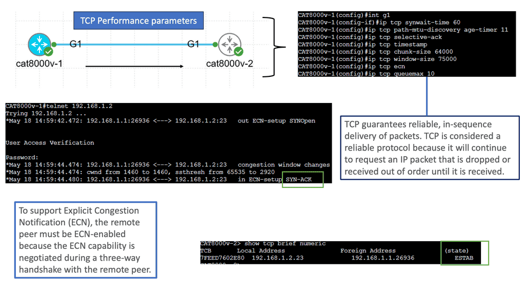
Understanding TCP Performance Parameters
TCP performance parameters are settings that govern the behavior and efficiency of TCP connections. These parameters control various aspects of the TCP protocol, including congestion control, window size, retransmission behavior, and more. Network administrators and engineers can tailor TCP behavior to specific network conditions and requirements by tweaking these parameters.
1. Window Size: The TCP window size determines how much data can be sent before receiving an acknowledgment. Optimizing the window size can help maximize throughput and minimize latency.
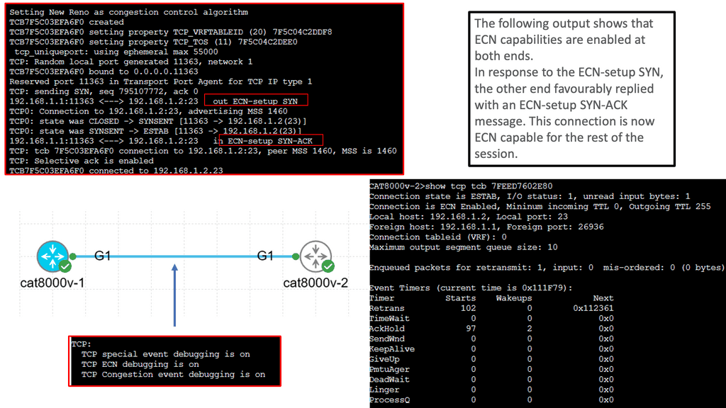
2. Congestion Control Algorithms: TCP employs various congestion control algorithms, such as Reno, New Reno, and Cubic. Each algorithm handles congestion differently, and selecting the appropriate one for specific network scenarios is vital.
3. Maximum Segment Size (MSS): MSS refers to the maximum amount of data sent in a single TCP segment. Adjusting the MSS can optimize efficiency and reduce the overhead associated with packet fragmentation.
Now that we understand the significance of TCP performance parameters let’s explore how to tune them for optimal performance. Factors such as network bandwidth, latency, and the specific requirements of the applications running on the network must be considered.
1. Analyzing Network Conditions: Conduct thorough network analysis to determine the ideal values for TCP performance parameters. This analysis examines round-trip time (RTT), packet loss, and available bandwidth.
2. Testing and Iteration: Implement changes to TCP performance parameters gradually and conduct thorough testing to assess the impact on network performance. Fine-tuning may require multiple iterations to achieve the desired results.
Various tools and utilities are available to simplify the process of monitoring and optimizing TCP performance parameters. Network administrators can leverage tools like Wireshark, TCPdump, and Netalyzer to analyze network traffic, identify bottlenecks, and make informed decisions regarding parameter adjustments.
What is TCP MSS?
– TCP MSS refers to the maximum amount of data encapsulated within a single TCP segment. It represents the largest payload size that can be sent over a TCP connection without fragmentation. MSS is primarily negotiated during the TCP handshake process, where the two communicating hosts agree upon an MSS value based on their respective capabilities.
– Several factors influence the determination of TCP MSS. One crucial factor is the network path’s Maximum Transmission Unit (MTU) between the communicating hosts. The MTU represents the maximum packet size that can be transmitted without fragmentation across the underlying network infrastructure. TCP MSS is generally set to the MTU minus the IP and TCP headers’ overhead. It ensures the data fits within a single packet and avoids unnecessary fragmentation.
– Understanding the implications of TCP MSS is essential for optimizing network performance. When the TCP MSS value is higher, it allows for larger data payloads in each segment, which can improve overall throughput. However, larger MSS values also increase the risk of packet fragmentation, especially if the network path has a smaller MTU. Fragmented packets can lead to performance degradation, increased latency, and potential retransmissions.
– To mitigate the issues arising from fragmentation, TCP utilizes a mechanism called Path MTU Discovery (PMTUD). PMTUD allows TCP to dynamically discover the smallest MTU along the network path and adjust the TCP MSS value accordingly. By determining the optimal MSS value, PMTUD ensures efficient data transmission without relying on packet fragmentation.

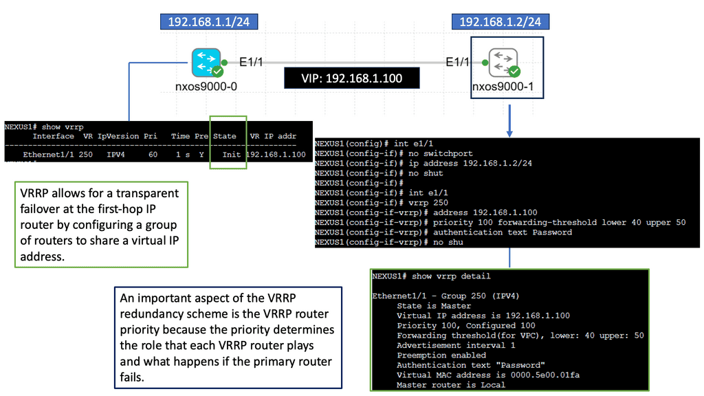
Understanding Nexus 9000 Series VRRP
At its core, Nexus 9000 Series VRRP is a dynamic routing protocol that allows for the creation of a virtual router that acts as a single point of contact for multiple physical routers. This virtual router offers redundancy and high availability by seamlessly enabling failover between the physical routers. By utilizing VRRP, network administrators can ensure that their networks remain operational despite hardware or software failures.
One of the standout features of Nexus 9000 Series VRRP is its ability to provide load balancing across multiple routers. By distributing network traffic intelligently, VRRP ensures optimal utilization of resources while preventing bottlenecks. Additionally, VRRP supports virtual IP addresses, allowing for transparent failover without requiring any changes in the network configuration. This flexibility makes Nexus 9000 Series VRRP an ideal choice for businesses with stringent uptime requirements.
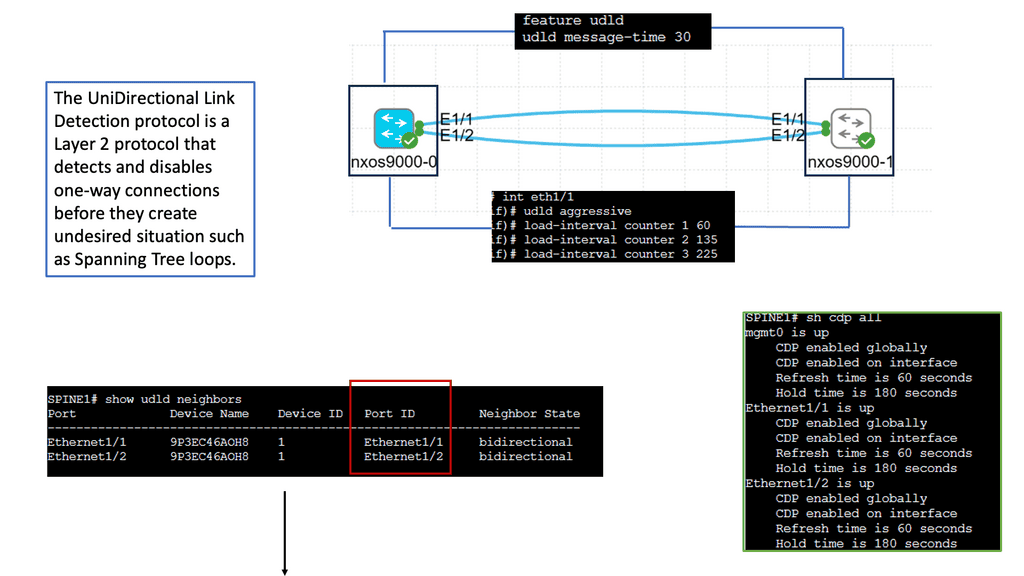
Understanding UDLD
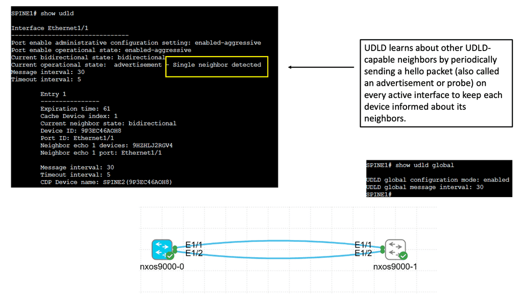
UDLD is a Layer 2 protocol that detects and mitigates unidirectional links, which can cause network loops and data loss. It operates by exchanging periodic messages between neighboring switches to verify that the link is bidirectional. If a unidirectional link is detected, UDLD immediately disables the affected port, preventing potential network disruptions.
Implementing UDLD brings several advantages to the network environment. Firstly, it enhances network reliability by proactively identifying and addressing unidirectional link issues. This helps to avoid potential network loops, packet loss, and other connectivity problems. Additionally, UDLD improves network troubleshooting capabilities by providing detailed information about the affected ports, facilitating quick resolution of link-related issues.
Configuring UDLD on Cisco Nexus 9000 switches is straightforward. It involves enabling UDLD globally on the device and enabling UDLD on specific interfaces. Additionally, administrators can fine-tune UDLD behavior by adjusting parameters such as message timers and retries. Proper deployment of UDLD in critical network segments adds an extra layer of protection against unidirectional link failures.
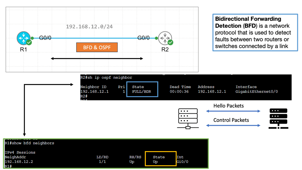
Example Technology: BFD for data center performance
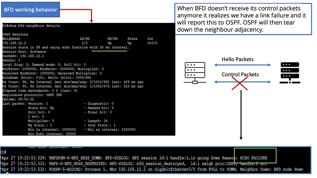
BFD, an abbreviation for Bidirectional Forwarding Detection, is a protocol to detect network path faults. It offers rapid detection and notification of link failures, improving network reliability. BFD data centers leverage this protocol to enhance performance and ensure seamless connectivity.
The advantages of optimal BFD data center performance are manifold. Let’s highlight a few key benefits:
a. Enhanced Network Reliability: BFD data centers offer enhanced fault detection capabilities, leading to improved network reliability. Identifying link failures allows quick remediation, minimizing downtime and ensuring uninterrupted connectivity.
b. Reduced Response Time: BFD data centers significantly reduce response time by swiftly detecting network faults. This is critical in mission-critical applications where every second counts, such as financial transactions, real-time communication, or online gaming.
c. Proactive Network Monitoring: BFD data centers enable proactive monitoring, giving administrators real-time insights into network performance. This allows for early detection of potential issues, enabling prompt troubleshooting and preventive measures.
Enhancing Stability & Improving Performance
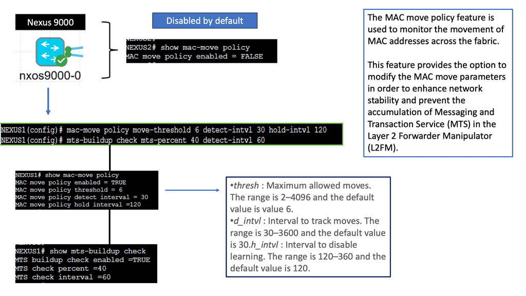
Understanding the MAC Move Policy
The MAC move policy, also known as the Move Limit feature, is designed to prevent MAC address flapping and enhance network stability. It allows network administrators to define how often a MAC address can move within a specified period before triggering an action. By comprehending the MAC move policy’s purpose and functionality, administrators can better manage their network’s stability and performance.
Troubleshooting MAC Move Issues
Network administrators may encounter issues related to MAC address moves despite implementing the MAC move policy. Here are some standard troubleshooting steps to consider:
1. Verifying MAC Move Configuration: It is crucial to double-check the MAC move configuration on Cisco NX-OS devices. Ensure that the policy is enabled correctly and that the correct parameters, such as aging time and notification settings, are applied.
2. Analyzing MAC Move Logs: Dive deep into the MAC move logs to identify any patterns or anomalies. Look for recurring MAC move events that may indicate a misconfiguration or unauthorized activity.
3. Reviewing Network Topology Changes: Changes in the network topology can sometimes lead to unexpected MAC moves. Analyze recent network changes, such as new device deployments or link failures, to identify potential causes for MAC move issues.
Modular Design and Flexibility
Modular design has emerged as a game-changer in data center scaling. Organizations can add or remove resources flexibly and cost-effectively by adopting a modular approach. Modular data center components like prefabricated server modules and containerized solutions allow for rapid deployment and easy scalability. This reduces upfront costs and enables businesses to have faster time to market.
Traditional Design and the Move to VPC
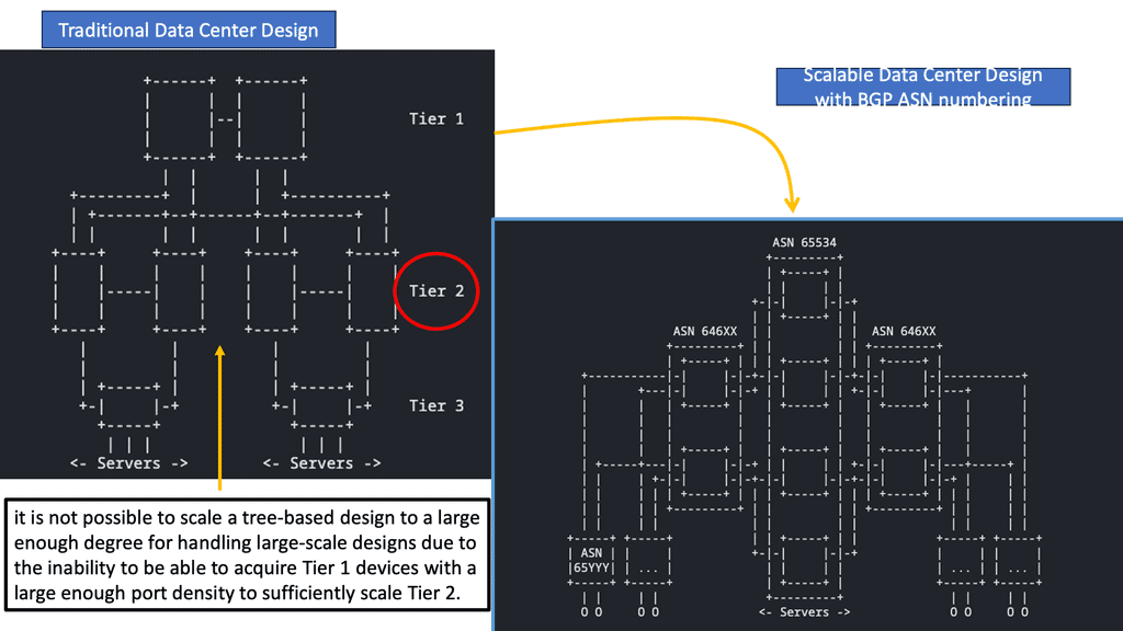
The architecture has three types of routers: core routers, aggregation routers (sometimes called distribution routers), and access switches. Layer 2 networks use the Spanning Tree Protocol to establish loop-free topologies between aggregation routers and access switches. The spanning tree protocol has several advantages.
There are several advantages to using this technology, including its simplicity and ease of use. The IP address and default gateway setting do not need to be changed when servers move within a pod because VLANs are extended within each pod. In a VLAN, Spanning Tree Protocol never allows redundant paths to be used simultaneously.
To overcome the limitations of the Spanning Tree Protocol, Cisco introduced virtual port channel (vPC) technology in 2010. A vPC eliminates blocked ports from spanning trees, provides active-active uplinks between access switches and aggregation routers, and maximizes bandwidth usage.
In 2003, virtual technology allowed computing, networking, and storage resources to be pooled previously segregated in pods in Layer 2 of the three-tier data center design. This revolutionary technology created a need for a larger Layer 2 domain.
Deploying virtualized servers makes applications increasingly distributed, resulting in increased east-west traffic due to the ability to access and share resources securely. Latency must be low and predictable to handle this traffic efficiently. In a three-tier data center, bandwidth becomes a bottleneck when only two active parallel uplinks are available; however, vPC can provide four active parallel uplinks. Three-tier architectures also present the challenge of varying server-to-server latency.
A new data center design based on the Clos network was developed to overcome these limitations. With this architecture, server-to-server communication is high-bandwidth, low-latency, and non-blocking
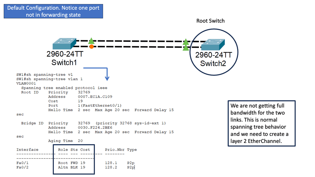
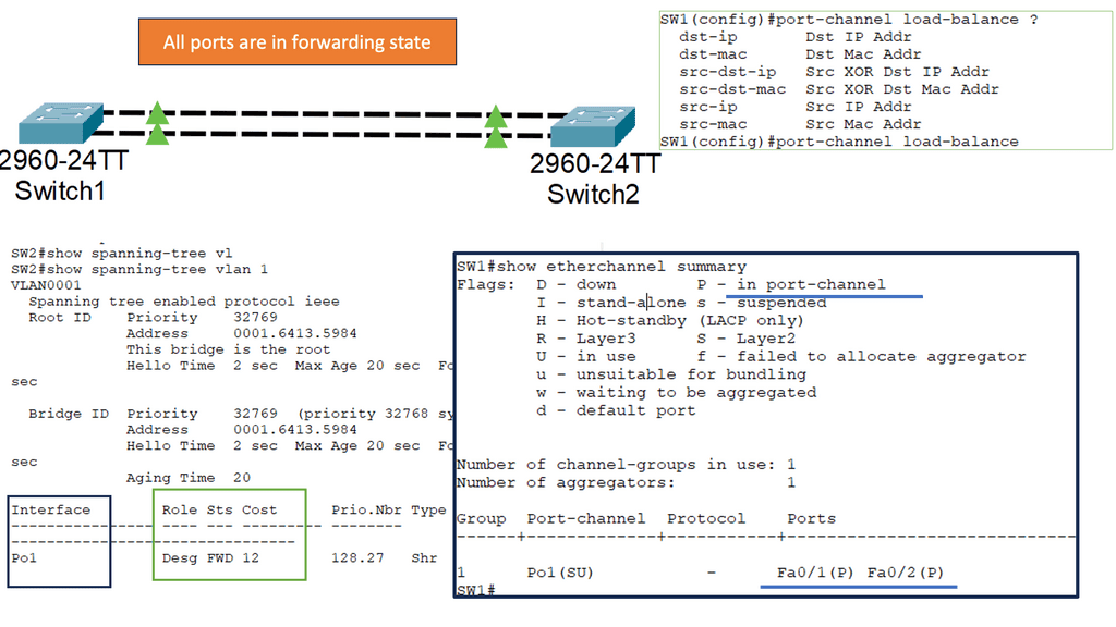
Understanding Layer 2 Etherchannel
Layer 2 Etherchannel, or Link Aggregation, allows multiple physical links between switches to be treated as a single logical link. This bundling of links increases the available bandwidth and provides load balancing across the aggregated links. It also enhances fault tolerance by creating redundancy in the network.
To configure Layer 2 Etherchannel, several steps need to be followed. Firstly, the participating interfaces on the switches need to be identified and grouped as a channel group. Once the channel group is formed, a protocol such as the Port Aggregation Protocol (PAgP) or Link Aggregation Control Protocol (LACP) must be selected to manage the bundle. The protocol ensures the links are synchronized and operate as a unified channel.
Understanding Layer 3 Etherchannel
Layer 3 Etherchannel, or routed Etherchannel, is a technique that aggregates multiple physical links into a single logical link. Unlike Layer 2 Etherchannel, which operates at the data link layer, Layer 3 Etherchannel operates at the network layer. This means it can provide load balancing and redundancy for routed traffic, making it a valuable asset in network design.
Firstly, the switches involved must support Layer 3 Etherchannel and have compatible configurations. Secondly, the physical links to be bundled should have the same speed and duplex settings. Additionally, the links must be connected to the same VLAN or bridge domain.
Once these prerequisites are fulfilled, the configuration process involves creating a port channel interface, assigning the physical interfaces to the port channel, and configuring appropriate routing protocols or static routes.

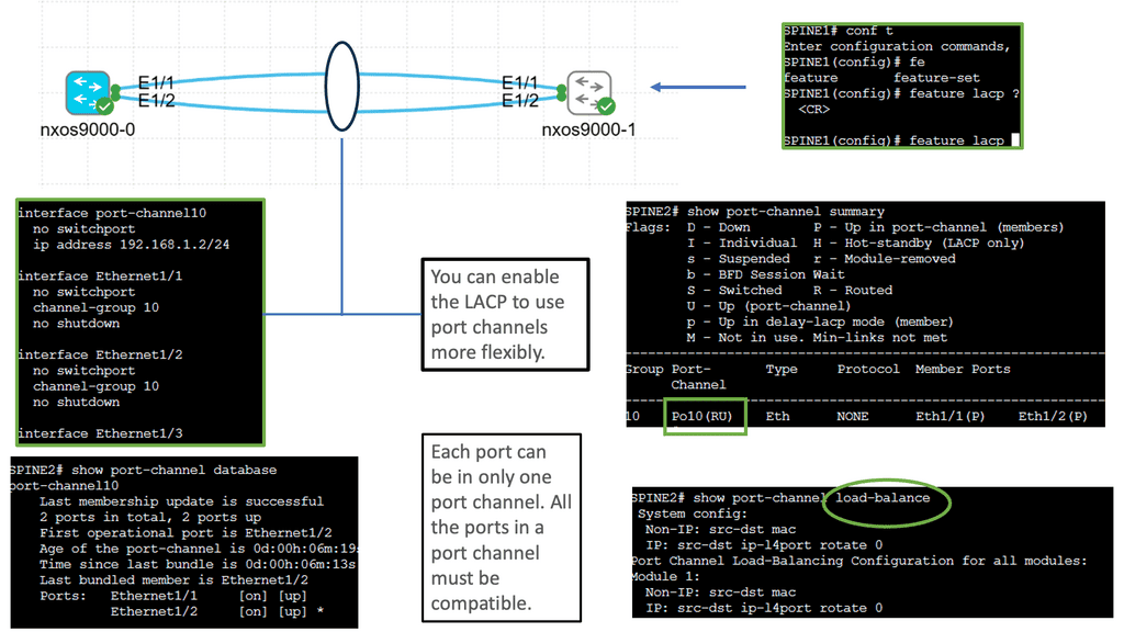
Understanding Cisco Nexus 9000 Port Channel
Port channeling, also known as link aggregation or EtherChannel, allows us to combine multiple physical links between switches into a single logical link. This logical link provides increased bandwidth, redundancy, and load-balancing capabilities, ensuring efficient utilization of network resources. The Cisco Nexus 9000 port channel takes this concept to a new level, offering advanced features and functionalities.
Configuring the Cisco Nexus 9000 port channel is a straightforward process. First, we need to identify the physical interfaces that will be part of the port channel. Then, we create the port-channel interface and assign it a number. Next, we associate the physical interfaces with the port channel using the “channel-group” command. We can also define additional parameters such as load balancing algorithm, mode (active or passive), and spanning tree protocol settings.
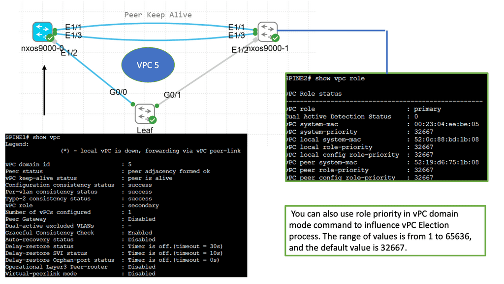
Understanding Virtual Port Channel (VPC)
VPC, in simple terms, enables the creation of a logical link aggregation between two Cisco Nexus switches. This link aggregation forms a single, robust connection, eliminating the need for Spanning Tree Protocol (STP) and providing active-active forwarding. By combining the bandwidth and redundancy of multiple physical links, VPC ensures high availability and efficient utilization of network resources.
Configuring VPC on Cisco Nexus 9000 Series switches involves a series of steps. Both switches must be configured with a unique domain ID and a peer-link interface. This peer-link serves as the control plane communication channel between the switches. Next, member ports are added to the VPC domain, forming a port channel. This port channel is assigned to VLANs, creating a virtual network spanning the switches. Lastly, VPC parameters such as peer gateway, auto-recovery, and graceful convergence can be fine-tuned to suit specific requirements.

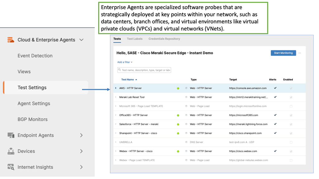
Example Product: Cisco ThousandEyes
### What is Cisco ThousandEyes?
Cisco ThousandEyes is a powerful network intelligence platform that provides end-to-end visibility into internet and cloud environments. It combines the strengths of both network monitoring and performance analytics, enabling businesses to identify, troubleshoot, and resolve performance issues in real-time. By leveraging Cisco ThousandEyes, organizations can gain a comprehensive understanding of their network’s health and performance, ensuring optimal data center operations.
### The Importance of Data Center Performance
Data centers are the backbone of modern businesses, hosting critical applications and services. Poor performance or downtime can lead to significant financial losses and damage to a company’s reputation. Therefore, maintaining high data center performance is crucial. Cisco ThousandEyes provides the tools and insights needed to monitor and optimize data center performance, ensuring that your business runs smoothly and efficiently.

### Key Features of Cisco ThousandEyes
Cisco ThousandEyes offers a plethora of features designed to enhance data center performance. Some of the key features include:
– **End-to-End Visibility**: Gain a holistic view of your network, from the data center to the cloud and beyond.
– **Real-Time Monitoring**: Track performance metrics in real-time, allowing for immediate detection and resolution of issues.
– **Advanced Analytics**: Leverage robust analytics to identify trends, predict potential problems, and optimize performance.
– **Seamless Integration**: Integrate seamlessly with existing Cisco solutions and other third-party tools, ensuring a unified approach to network management.
### Benefits of Using Cisco ThousandEyes for Data Center Performance
Adopting Cisco ThousandEyes for your data center performance management brings numerous benefits:
– **Improved Reliability**: Ensure consistent and reliable performance, minimizing downtime and disruptions.
– **Enhanced User Experience**: Provide a superior user experience by identifying and addressing performance bottlenecks promptly.
– **Cost Savings**: Reduce operational costs by optimizing resource usage and avoiding costly downtime.
– **Informed Decision Making**: Make data-driven decisions with actionable insights and detailed performance reports.
Advanced Topics
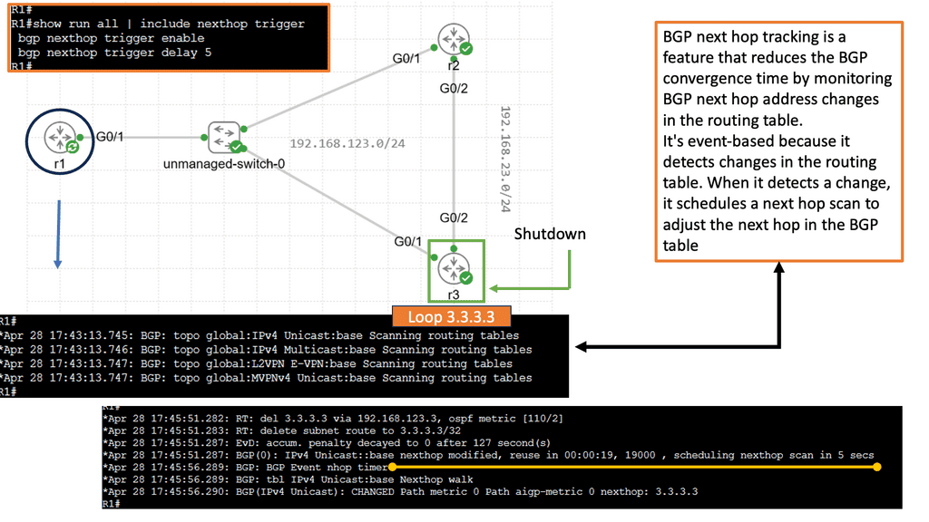
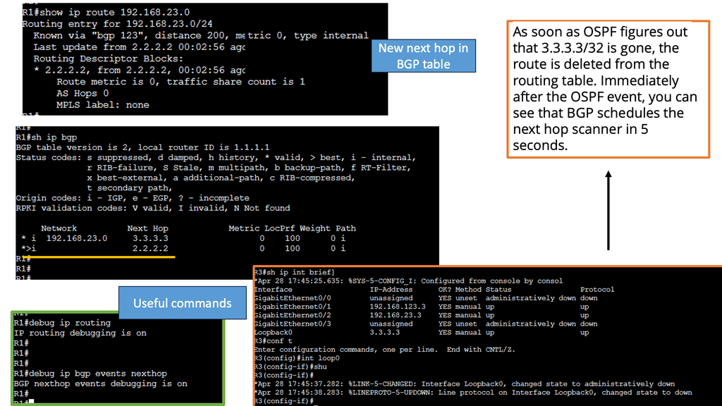
BGP Next Hop Tracking:
BGP next hop refers to the IP address used to reach a specific destination network. It represents the next hop router or gateway that should be used to forward packets towards the intended destination. Unlike traditional routing protocols, BGP considers multiple paths to reach a destination and selects the best path based on path length, AS (Autonomous System) path, and next hop information.
Importance of Next Hop Tracking:
Next-hop tracking within BGP is paramount as it ensures the proper functioning and stability of the network. By accurately tracking the next hop, BGP can quickly adapt to changes in network topology, link failures, or routing policy modifications. This proactive approach enables faster convergence times, reduces packet loss, and optimizes network performance.
Implementing BGP next-hop tracking offers network administrators and service providers numerous benefits. Firstly, it enhances network stability by promptly detecting and recovering from link failures or changes in network topology. Secondly, it optimizes traffic engineering capabilities, allowing for efficient traffic distribution and load balancing. Next-hop tracking improves network security by preventing route hijacking or unauthorized traffic diversion.
Understanding BGP Route Reflection
BGP route reflection is a mechanism to alleviate the complexity of full-mesh BGP configurations. It allows for the propagation of routing information without requiring every router to establish a direct peering session with every other router in the network. Instead, route reflection introduces a hierarchical structure, dividing routers into different clusters and designating route reflectors to handle the distribution of routing updates.
Implementing BGP route reflection brings several advantages to large-scale networks. Firstly, it reduces the number of peering sessions required, resulting in simplified network management and reduced resource consumption. Moreover, route reflection enhances scalability by eliminating the need for full-mesh configurations, enabling networks to accommodate more routers. Additionally, route reflectors improve convergence time by propagating routing updates more efficiently.


Overcoming Challenges: Power and Cooling
As data centers strive to achieve faster speeds, they face significant power consumption and cooling challenges. High-speed processing and networking equipment generate substantial heat, necessitating robust cooling mechanisms to maintain optimal performance. Efficient cooling solutions, such as liquid cooling and advanced airflow management, are essential to prevent overheating and ensure data centers can operate reliably at peak speeds. As data centers become more powerful, cooling becomes a critical challenge.
- Liquid Cooling
In the relentless pursuit of higher computing power, data centers turn to liquid cooling as a game-changing solution. By immersing servers in a specially designed coolant, heat dissipation becomes significantly more efficient. This technology allows data centers to push the boundaries of performance and offers a greener alternative by reducing energy consumption.
- Artificial Intelligence Optimization
Artificial Intelligence (AI) is making its mark in data center performance. By leveraging machine learning algorithms, data centers can optimize their operations in real-time. AI-driven predictive analysis helps identify potential bottlenecks and enables proactive maintenance, improving efficiency and reducing downtime.
- Edge Computing
With the exponential growth of Internet of Things (IoT) devices, data processing at the network’s edge has become necessary. Edge computing brings computation closer to the data source, reducing latency and bandwidth requirements. This innovative approach enhances data center performance and enables faster response times and improved user experiences.
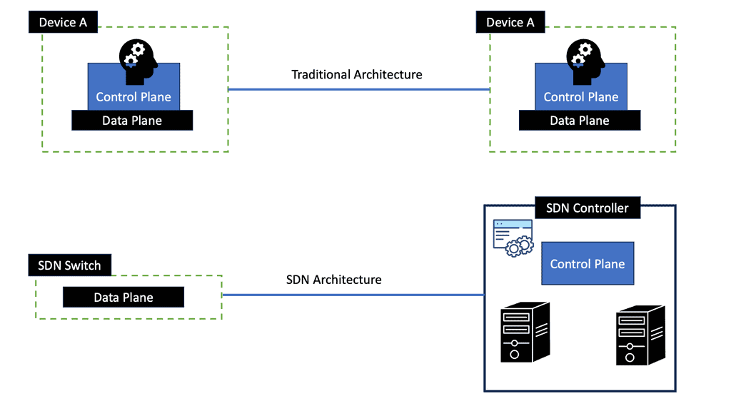
- Software-Defined Networking
Software-defined networking (SDN) redefines how data centers manage and control their networks. By separating the control plane from the data plane, SDN allows centralized network management and programmability. This flexibility enables data centers to dynamically allocate resources, optimize traffic flows, and adapt to changing demands, enhancing performance and scalability.
**Switch Fabric Architecture**
Switch fabric architecture is crucial to minimize packet loss and increase data center performance. A Gigabit (10GE to 100GE) data center network only takes milliseconds of congestion to cause buffer overruns and packet loss. Selecting the correct platforms that match the traffic mix and profiles is an essential phase of data center design. Specific switch fabric architectures are better suited to certain design requirements. Network performance has a direct relationship with switching fabric architecture.
The data center switch fabric aims to optimize end-to-end fabric latency with the ability to handle traffic peaks. Environments should be designed to send data as fast as possible, providing better application and storage performance. For these performance metrics to be met, several requirements must be set by the business and the architect team.
Before you proceed, you may find the following post helpful for pre-information.
Several key factors influence data center performance:
a. Uptime and Reliability: Downtime can have severe consequences for businesses, resulting in financial losses, damaged reputation, and even legal implications. Therefore, data centers strive to achieve high uptime and reliability, minimizing disruptions to operations.
b. Speed and Responsiveness: With increasing data volumes and user expectations, data centers must deliver fast and responsive services. Slow response times can lead to dissatisfied customers and hamper business productivity.
c. Scalability: As businesses grow, their data requirements increase. A well-performing data center should be able to scale seamlessly, accommodating the organization’s expanding needs without compromising on performance.
d. Energy Efficiency: Data centers consume significant amounts of energy. Optimizing energy usage through efficient cooling systems, power management, and renewable energy sources can reduce costs and contribute to a sustainable future.
Impact on Businesses:
Data center performance directly impacts businesses in several ways:
a. Enhanced User Experience: A high-performing data center ensures faster data access, reduced latency, and improved website/application performance. This translates into a better user experience, increased customer satisfaction, and higher conversion rates.
b. Business Continuity: Data centers with robust performance measures, including backup and disaster recovery mechanisms, help businesses maintain continuity despite unexpected events. This ensures that critical operations can continue without significant disruption.
c. Competitive Advantage: In today’s competitive landscape, businesses that leverage the capabilities of a well-performing data center gain a competitive edge. Processing and analyzing data quickly can lead to better decision-making, improved operational efficiency, and innovative product/service offerings.
Proactive Testing
Although the usefulness of proactive testing is well known, most do not vigorously and methodically stress their network components in the ways that their applications will. As a result, too infrequent testing returns significantly less value than the time and money spent. In addition, many existing corporate testing facilities are underfunded and eventually shut down because of a lack of experience and guidance, limited resources, and poor productivity from previous test efforts. That said, the need for testing remains.
To understand your data center performance, you should undergo planned system testing. System testing is a proven approach for validating the existing network infrastructure and planning its future. It is essential to comprehend that in a modern enterprise network, achieving a high level of availability is only possible with some formalized testing.
Different Types of Switching
Cut-through switching
Cut-through switching allows you to start forwarding frames immediately. Switches process frames using a “first bit in, first bit out” method.
When a switch receives a frame, it makes a forwarding decision based on the destination address, known as destination-based forwarding. On Ethernet networks, the destination address is the first field following the start-of-frame delimiter. Due to the positioning of the destination address at the start of the frame, the switch immediately knows what egress port the frame needs to be sent to, i.e., there is no need to wait for the entire frame to be processed before you carry out the forwarding.
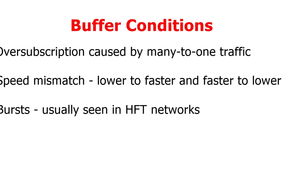
Buffer pressure at the leaf switch uplink and corresponding spine port is about the same, resulting in the same buffer size between these two network points. However, increasing buffering size at the leaf layer is more critical as more cases of speed mismatch occur in the cast ( many-to-one ) traffic and oversubscription. Speed mismatch, incast traffic, and oversubscription are the leading causes of buffer utilization.
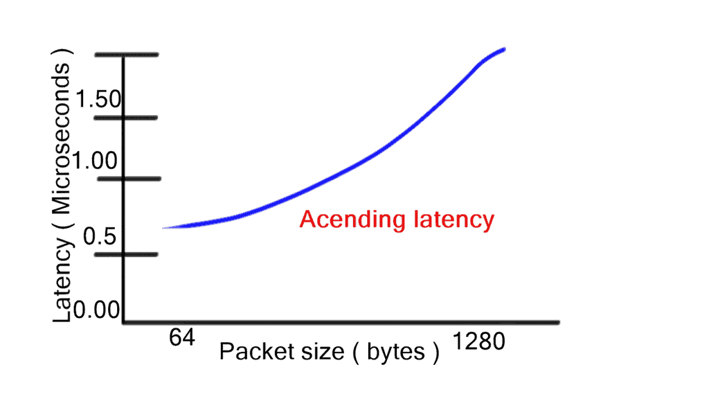
Store-and-forwarding
Store-and-forwarding works in contrast to cut-through switching. However, store-and-forwarding switching increases latency with packet size as the entire frame is stored first before the forwarding decision is made. One of the main benefits of cut-through is consistent latency among packet sizes, which is suitable for network performance. However, there are motivations to inspect the entire frame using the store-and-forward method. Store-and-forward ensures a) Collision detection and b) No packets with errors are propagated.
Cut-through switching is a significant data center performance improvement for switching architectures. Regardless of packet sizes, cut-through reduces the latency of the lookup-and-forwarding decision. Low and predictable latency results in optimized fabric and more minor buffer requirements. Selecting the correct platform with adequate interface buffer space is integral to data center design. For example, different buffering size requirements exist for leaf and spine switches. In addition, varying buffering utilization exists for other points of the network.
Switch Fabric Architecture
The main switch architectures used are the crossbar and SoC. A cut-through or store-and-forward switch can use either a crossbar fabric, a multistage crossbar fabric, an SoC, or a multistage SoC with either.
Crossbar Switch Fabric Architecture
In a crossbar design, every input is uniquely connected to every output through a “crosspoint. ” With a crosspoint design, crossbar fabric is strictly non-blocking and provides lossless transport. In addition, it has a feature known as over speed, which is used to achieve a 100% throughput (line rate) capacity for each port.
Overspeed clocks the switch fabric several times faster than the physical port interface connected to the fabric. Crossbar and cut-through switching enable line-rate performance with low latency regardless of packet size.
Cisco Nexus 6000 and 5000 series are cut-through with the crossbar. Nexus 7000 uses store-and-forward crossbar-switching mechanisms with large output-queuing memory or egress buffer.
Because of the large memory store-and-forward crossbar design offered, they provide large table sizes for MAC learning. Due to large table sizes, the density of ports is lower than that of other switch categories. The Nexus 7000 series with an M-series line card exemplifies this architecture.
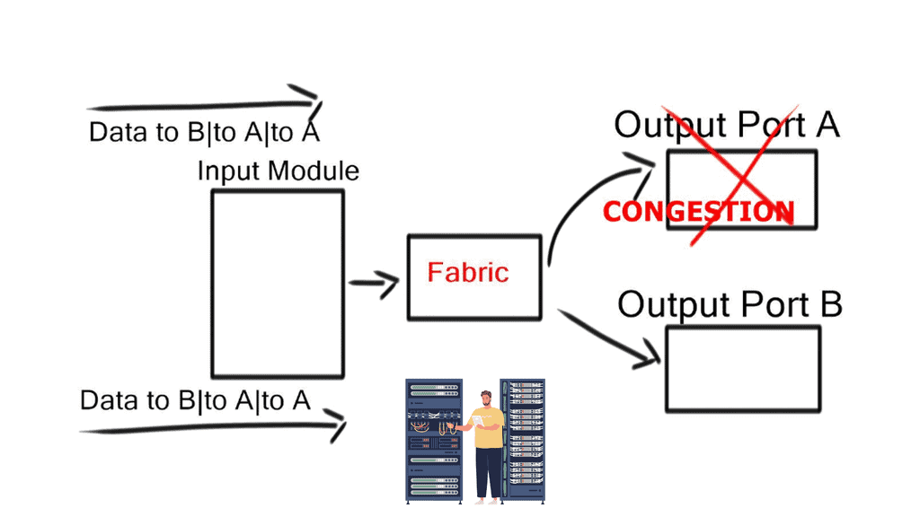
Head-of-line blocking (HOLB)
When frames for different output ports arrive on the same ingress port, a frame destined for a free output port can be blocked by a frame in front of it destined for a congested output port. For example, an extensive FTP transfer lands in the same path across the internal switching fabric, in addition to the request-response protocol (HTTP), which handles short transactions.
This causes the frame destined for the free port to wait in a queue until the frame in front of it can be processed. This idle time degrades performance and can create out-of-order frames.
Virtual output queues (VoQ)
Instead of having a single per-class queue on an output port, the hardware implements a per-class virtual output queue (VoQ) on input ports. Received packets stay in the virtual output queue on the input line card until the output port is ready to accept another packet. With VoQ, data centers no longer experience HOLB. VoQ is effective at absorbing traffic loads at congestion points in the network.
It forces congestion on ingress/queuing before traffic reaches the switch fabric. Packets are held at the ingress port buffer until the egress queue frees up.
VoQ is not the same as ingress queuing. Ingress queuing occurs when the total ingress bandwidth exceeds backplane capacity, and actual congestion occurs, which ingress-queuing policies would govern. VoQ generates a virtual congestion scenario at a node before the switching fabric. They are governed by egress queuing policies, not ingress policies.
Centralized shared memory ( SoC )
SoC is another type of data center switch architecture. Lower bandwidth and port density switches usually have SoC architectures. SoC differs from the crossbar in that all inputs and outputs share all memory. This inherently reduces frame loss and drop probability. Unused buffers are given to ports under pressure from increasing loads.
Closing Points: Data Center Performance
At its core, a data center is a facility composed of networked computers and storage that businesses use to organize, process, store, and disseminate large amounts of data. The performance of a data center hinges on several components, including servers, networking equipment, and storage systems. Each element must work harmoniously to support the smooth execution of applications and services.
One often overlooked aspect of data center performance is the cooling system. With so much equipment generating heat, effective cooling is vital to maintain optimal operating conditions and prevent hardware failures. Implementing advanced cooling technologies, such as liquid cooling or energy-efficient air conditioning systems, can significantly enhance performance while reducing energy consumption and costs.
Virtualization technology allows for the creation of virtual versions of physical hardware, enabling multiple virtual machines to run on a single physical server. This not only maximizes resource utilization but also facilitates easier management and scalability. By leveraging virtualization, data centers can reduce their physical footprint and improve overall efficiency, leading to cost savings and increased performance.
Continuous monitoring and automation are essential for maintaining optimal data center performance. By utilizing monitoring tools, administrators can track key performance indicators such as CPU usage, power consumption, and network traffic. Automation can further enhance efficiency by streamlining routine tasks, such as patch management and system updates, allowing IT teams to focus on more strategic initiatives.
Optimizing data center performance is a multifaceted endeavor that requires a comprehensive approach. By focusing on cooling systems, leveraging virtualization, and embracing monitoring and automation, data centers can achieve greater efficiency and reliability. As we continue to rely heavily on digital infrastructure, ensuring the optimal performance of data centers will remain a priority for businesses and IT professionals alike.