
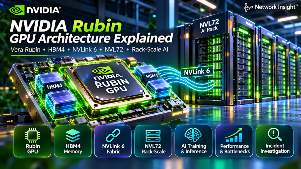
Inside NVIDIA Rubin: The Next Generation of AI Computing Infrastructure
NVIDIA Rubin represents a new generation of accelerated computing architecture designed for increasingly demanding AI training and inference workloads. The platform brings together Rubin GPUs, Vera CPUs, HBM4 memory, high-bandwidth NVLink 6 communication and rack-scale integration.
Understanding Rubin requires looking beyond GPU compute performance. Modern AI systems depend on coordinated advances in processor architecture, memory bandwidth, interconnect technology, networking, power delivery and cooling.
Rubin GPU Compute Architecture
The Rubin GPU provides accelerated computation for AI workloads. Its performance must be understood alongside memory bandwidth, communication requirements and the broader system architecture.
Rubin as a Complete AI Computing Platform
Rubin should be understood as part of an integrated accelerated computing system rather than an isolated GPU. The architecture combines compute resources, high-bandwidth memory, CPU integration and high-speed communication infrastructure.
For large AI workloads, system performance depends on how effectively these components exchange data and coordinate computation.
Why Rack-Scale Architecture Matters
Modern AI training and inference increasingly require multiple accelerators working together. Rack-scale integration brings compute, interconnect, power and cooling into a coordinated platform architecture.
The Vera Rubin NVL72 platform extends this approach by combining Vera CPUs and Rubin GPUs with an NVLink-based scale-up fabric.
Engineering perspective: GPU compute capability alone does not determine AI infrastructure performance. Memory capacity and bandwidth, collective communication, interconnect topology, software execution and system-level power constraints all contribute to workload efficiency.
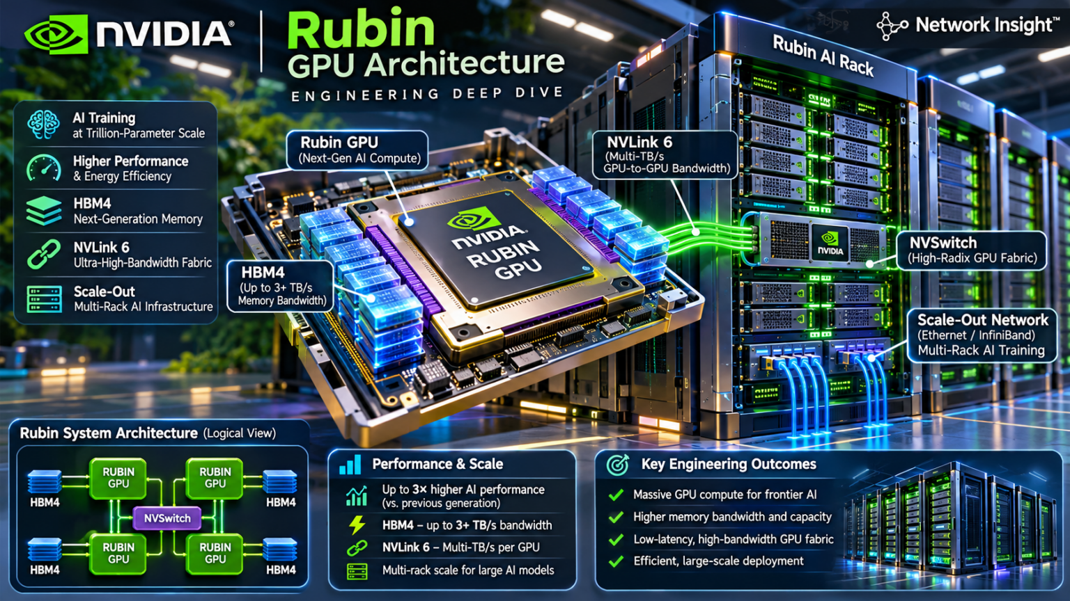
Explore the NVIDIA Vera Rubin Architecture
Nine engineering chapters. One integrated AI computing platform. Select an architecture node to inspect its role, then jump directly to the corresponding section.
Architecture Navigator
Choose a section from the list or the animated architecture diagram.
01 — Rubin Architecture Fundamentals
Explore the architecture of NVIDIA's Rubin accelerated computing platform.
Understanding the Vera Rubin AI Computing Platform
NVIDIA Rubin represents an evolution in accelerated computing infrastructure. The platform combines Rubin GPU acceleration, Vera CPU processing, HBM4 memory and NVLink 6 communication to support demanding AI training and inference workloads.
Rather than viewing the GPU as an independent compute device, engineers must understand the relationships between processors, memory systems, interconnects and rack-scale infrastructure. Each layer contributes to application throughput, latency, scalability and operational efficiency.
Integrated Vera Rubin Architecture
The Vera Rubin platform combines CPU processing, GPU acceleration, high-bandwidth memory and high-speed communication infrastructure within an integrated system architecture.
1. Rubin as a Platform Architecture
The Rubin generation is designed as part of a broader accelerated computing platform. The GPU provides AI computation, while CPUs, memory systems and interconnects support execution, data movement and scaling.
This system-level approach reflects the growing complexity of AI workloads that require coordinated processing across many accelerators.
2. The Role of the Rubin GPU
The Rubin GPU is the central acceleration component for supported AI workloads. Its compute capabilities must be evaluated alongside memory performance and communication requirements.
Large models can be limited by memory bandwidth, synchronization or interconnect capacity even when substantial compute resources are available.
Architecture principle: A modern AI accelerator is only one part of the performance equation. Effective AI infrastructure combines compute, memory, communication, software execution and system-level integration.
3. Vera CPU Integration
The Vera CPU provides host processing capabilities within the platform. CPU resources support system execution and coordination while Rubin GPUs perform accelerated computation.
CPU–GPU integration affects application orchestration, data movement and the efficiency of workloads that involve both general-purpose and accelerated processing.
4. HBM4 Memory Architecture
HBM4 is a high-bandwidth memory technology used in the Rubin architecture. GPU memory bandwidth and capacity influence the ability to process large models and move data efficiently through compute pipelines.
Memory-intensive workloads may be limited by data access patterns rather than arithmetic throughput alone.
5. NVLink 6 and Scale-Up Communication
NVLink 6 provides high-bandwidth communication capabilities for supported Rubin systems. It is part of the scale-up communication architecture connecting accelerators within supported system topologies.
Scale-up communication is particularly important for workloads requiring frequent GPU-to-GPU data exchange.
6. Rack-Scale AI Infrastructure
The Vera Rubin NVL72 platform extends accelerated computing to a rack-scale architecture. This integrates compute and communication resources with supporting power delivery and cooling infrastructure.
Rack-scale engineering introduces additional considerations involving operational reliability, thermal management and infrastructure density.
7. The AI Communication Hierarchy
Large AI systems involve multiple communication layers. Data moves within GPU memory, between CPUs and GPUs, among accelerators in a scale-up domain and between systems through scale-out networking.
Understanding these boundaries is essential for distributed AI architecture, workload placement and performance troubleshooting.
| Architecture component | Primary function | Engineering consideration |
|---|---|---|
| Rubin GPU | AI acceleration | Compute throughput and execution efficiency |
| Vera CPU | Host processing | CPU–GPU integration and application coordination |
| HBM4 | GPU memory | Memory capacity, bandwidth and access patterns |
| NVLink 6 | Scale-up interconnect | GPU communication and topology |
| NVSwitch | GPU fabric switching | Multi-GPU communication architecture |
| NVL72 | Rack-scale platform | Compute integration, power and cooling |
Engineering takeaway: The Rubin platform should be evaluated as a complete AI computing system. Compute performance, memory behavior, interconnect capabilities and rack-level infrastructure all influence the efficiency of large-scale workloads.
8. Engineering Takeaway
NVIDIA Rubin architecture brings together GPU compute, CPU integration, high-bandwidth memory and interconnect technologies within a broader AI infrastructure platform.
Understanding the relationships between these components provides the foundation for studying Rubin compute internals, HBM4, NVLink 6 and Vera Rubin NVL72 in the following sections.
This diagram is conceptual. Detailed hardware capabilities, physical integration and supported configurations should be checked against the documentation for the specific Rubin platform.
NVIDIA Vera Rubin Architecture Explorer
Explore Rubin GPU compute, HBM4, Vera CPU, NVLink 6, NVSwitch and external AI networking. Select components or execute an illustrative workload journey.
Vera–Rubin integrated system
Tap a component to inspect its engineering responsibility.
Choose a workload and run its execution journey.
Rubin integrates compute, high-bandwidth memory, CPU orchestration, scale-up communication and external networking.
Inside the Rubin GPU: Tensor Processing, Matrix Execution and AI Compute Pipelines
The NVIDIA Rubin GPU architecture is designed for computationally intensive AI workloads, including model training and inference. Understanding its role requires examining how GPU execution resources process tensor operations, access high-bandwidth memory and coordinate data movement.
AI performance depends on more than theoretical arithmetic throughput. Tensor Core execution, numerical precision, memory locality, parallelism and communication overhead all influence how efficiently a workload uses available GPU resources.
AI Compute Pipeline Overview
The conceptual pipeline shows how tensor data is accessed from memory, processed through GPU execution resources and transformed into output results.
1. Understanding Rubin GPU Compute Architecture
Rubin GPUs are part of NVIDIA's accelerated computing platform for AI training and inference. GPU execution resources are designed to process highly parallel workloads, particularly tensor and matrix operations commonly used in neural networks.
The practical performance of a GPU depends on its execution architecture, supported numerical formats, memory subsystem and software stack.
2. Tensor Core Processing
Tensor Cores are specialized GPU execution resources designed to accelerate supported matrix operations. These operations are fundamental to neural network training and inference.
Matrix multiplication appears in transformer attention, feed-forward layers and many other AI computations.
The exact capabilities and numerical formats available depend on the GPU generation and supported software libraries.
Compute principle: High arithmetic throughput does not automatically translate into high application performance. GPU kernels must provide enough parallel work, use supported numerical formats efficiently and minimize unnecessary memory movement.
3. Matrix Multiplication and AI Workloads
Many neural network operations can be represented as matrix multiplication. A simplified operation multiplies an input matrix by a weight matrix to produce an output matrix.
In practice, AI frameworks and GPU libraries organize matrix operations into tiled workloads that can be executed efficiently by available GPU processing resources.
Performance depends on matrix dimensions, data types, memory access patterns and the implementation selected by the software stack.
4. Numerical Precision and AI Execution
AI workloads use different numerical representations depending on accuracy, performance and memory requirements. Lower-precision formats can reduce data movement and increase computational efficiency when supported by the hardware and application.
Training and inference may require different precision strategies. Numerical stability, quantization error and model quality must be considered when selecting a format.
5. GPU Parallel Execution
GPUs achieve high throughput by executing many operations concurrently. AI frameworks divide workloads into kernels and parallel tasks that can be scheduled across available execution resources.
Effective parallelism depends on workload size, execution dependencies, memory availability and the ability to keep processing resources occupied.
6. Compute-Bound vs Memory-Bound Workloads
A compute-bound workload is primarily limited by the rate at which arithmetic operations can be executed. A memory-bound workload is primarily limited by how quickly required data can be supplied to the compute units.
These bottlenecks require different optimization strategies. Increasing arithmetic throughput will not necessarily improve a workload whose limiting factor is memory bandwidth.
| Workload characteristic | Primary constraint | Engineering focus |
|---|---|---|
| Compute-bound | Arithmetic execution throughput | Kernel efficiency, parallelism and supported precision |
| Memory-bound | Data access and memory bandwidth | Locality, reuse and memory traffic |
| Latency-sensitive | Execution and scheduling delay | Kernel launch overhead and critical-path latency |
| Communication-bound | Data exchange between devices | Interconnect topology and collective efficiency |
| Mixed workload | Multiple interacting constraints | Profiling and balanced optimization |
7. The Relationship Between Compute and HBM4
HBM4 provides high-bandwidth memory resources for the Rubin architecture. AI workloads require efficient access to model weights, activations and intermediate results.
Memory capacity influences the size of models and working sets that can be held locally, while memory bandwidth affects how quickly data can be delivered to execution resources.
8. Software and Kernel Optimization
GPU performance is influenced by the software stack, including CUDA, AI frameworks, compiler optimizations and accelerated libraries.
Kernel selection, tensor layout, batching, fusion and memory reuse can significantly affect the efficiency of a workload.
Performance analysis should therefore combine hardware understanding with application-level profiling.
Engineering takeaway: Rubin GPU performance must be evaluated as a combination of execution throughput, numerical precision, memory bandwidth, parallelism and software efficiency. The dominant bottleneck depends on the workload rather than the GPU specification alone.
9. Engineering Takeaway
The Rubin GPU compute architecture forms the processing foundation of the Vera Rubin platform. Tensor processing, matrix execution, numerical precision and parallel scheduling are central to modern AI acceleration.
Understanding these concepts prepares engineers to examine HBM4 memory architecture and the broader communication hierarchy in subsequent sections.
The pipeline and workload descriptions are conceptual. Specific Rubin execution capabilities, supported precision formats and performance characteristics should be verified against NVIDIA's platform documentation.
Rubin Compute Pipeline Lab
Inspect a conceptual GPU execution pipeline. Compare attention, matrix multiplication and inference decode; change precision and workload size; then step through scheduling, data staging, Tensor Core operations, accumulation and output.
GPU compute execution — conceptual architecture
Select any stage in the architecture diagram or run the pipeline to inspect its role.
Matrix multiplication represents dense tensor arithmetic. Performance depends on data layout, tile reuse, precision and available compute resources.
Compare precision modes and workload sizes. Inspect which stages involve data preparation versus arithmetic execution.
Inside HBM4: High-Bandwidth Memory, GPU Data Movement and AI Workload Performance
High-bandwidth memory is a critical component of modern AI accelerator architecture. NVIDIA Rubin uses HBM4 memory technology to support the data-intensive requirements of AI training and inference.
Understanding HBM4 requires examining how memory resources supply data to GPU compute units, how bandwidth and capacity influence model execution, and why memory locality and data reuse are central to performance engineering.
HBM4 Memory Architecture Overview
HBM4 provides high-bandwidth memory resources for Rubin GPU workloads. Memory performance depends on data access patterns, workload size and the efficiency of communication between memory and compute resources.
1. Understanding HBM4 Memory Architecture
HBM4 is a generation of high-bandwidth memory designed for demanding computing workloads. It uses stacked memory technology and a wide interface to support high data transfer rates.
Within a GPU system, high-bandwidth memory supplies model parameters, activations and intermediate results required by compute operations.
2. Why Memory Bandwidth Matters
GPU execution resources require a continuous supply of data. When memory cannot deliver data quickly enough, compute units may spend time waiting rather than performing useful arithmetic operations.
Memory bandwidth therefore influences the performance of AI workloads, especially those with large data movement requirements or limited opportunities for data reuse.
Memory architecture principle: GPU performance depends on the relationship between arithmetic intensity and memory traffic. Increasing compute capability does not eliminate memory bottlenecks when workloads must repeatedly transfer large amounts of data.
3. HBM4 Memory Stacks
High-bandwidth memory uses vertically stacked memory dies connected through advanced packaging technology. This approach enables a wide memory interface and high aggregate bandwidth.
Memory stack organization, capacity and supported data rates depend on the specific memory devices and GPU package implementation.
Engineers should distinguish the general HBM4 technology from the exact memory configuration of a particular Rubin product.
4. GPU Memory Controllers and Data Access
GPU memory controllers coordinate requests between execution resources and external memory. The efficiency of memory access depends on request patterns, concurrency, locality and the behavior of the memory subsystem.
Irregular access patterns and excessive memory traffic can reduce effective bandwidth compared with idealized peak specifications.
5. HBM4 and Large AI Models
Large AI models require substantial memory for parameters, activations and temporary execution data. In inference systems, the key-value cache can also consume significant memory depending on sequence length, batching and model architecture.
When the required working set exceeds available memory capacity, applications may need to distribute data across devices, reduce memory usage or employ alternative execution strategies.
6. Memory-Bound AI Workloads
A memory-bound workload is limited primarily by data access rather than arithmetic execution. Its performance can be improved through techniques that reduce unnecessary memory movement or increase reuse.
Optimization strategies may include kernel fusion, tiling, efficient tensor layouts and improved caching behavior.
7. Arithmetic Intensity and the Roofline Model
Arithmetic intensity describes the amount of computation performed relative to the amount of data transferred from memory.
Workloads with low arithmetic intensity are more likely to encounter memory bandwidth limitations. Workloads with high arithmetic intensity may become limited by available compute throughput.
The roofline model provides a useful framework for understanding this relationship, although real applications may encounter additional constraints.
| Memory characteristic | Impact on AI workloads | Engineering consideration |
|---|---|---|
| HBM capacity | Model and working-set size | Model placement and memory allocation |
| HBM bandwidth | Rate of data delivery | Memory-bound kernel performance |
| Memory locality | Data reuse efficiency | Tensor layout and caching |
| Arithmetic intensity | Compute-to-memory balance | Roofline performance analysis |
| Memory pressure | Available execution headroom | Batching, activations and KV cache |
8. Memory Performance Engineering
Memory performance should be evaluated using application profiling, supported GPU telemetry and representative workloads. Peak memory bandwidth figures describe theoretical capabilities rather than guaranteed application throughput.
Engineers should examine memory utilization, achieved bandwidth, data access patterns and kernel execution behavior when investigating memory-related performance problems.
Engineering takeaway: HBM4 provides the memory foundation for Rubin GPU workloads, but application performance depends on effective bandwidth, capacity requirements, data reuse and the balance between memory traffic and arithmetic execution.
9. Engineering Takeaway
HBM4 memory architecture is central to understanding how Rubin GPUs execute large AI workloads. Memory bandwidth supports data delivery, capacity determines available working-set space and locality influences execution efficiency.
These principles provide the foundation for exploring CPU–GPU integration, NVLink communication and rack-scale AI infrastructure in subsequent sections.
The illustrated memory stacks and pressure levels are conceptual. They do not represent the physical stack count, exact memory configuration or measured performance of an NVIDIA Rubin GPU.
HBM4 Memory Performance Explorer
Investigate memory bandwidth, capacity, data movement and arithmetic intensity across Rubin AI workloads. Determine whether the selected workload is constrained by GPU computation or memory performance.
Rubin GPU and HBM4 memory architecture
Select the Rubin GPU or an HBM4 stack to inspect its role in the memory hierarchy.
Configure a workload and run the analysis.
Compare model size, arithmetic intensity, memory bandwidth and compute throughput before identifying a performance bottleneck.
Inside Vera–Rubin: CPU Processing, Coherent Communication and Accelerated AI Execution
The NVIDIA Vera CPU provides the general-purpose processing foundation for the Vera Rubin accelerated computing platform. It works alongside Rubin GPUs, supporting system execution, application orchestration and the movement of data between CPU and GPU resources.
CPU–GPU integration is an important architectural consideration for modern AI infrastructure. Efficient communication, memory access, synchronization and workload placement influence the performance of training and inference applications.
Integrated Vera–Rubin System
Vera CPU processing and Rubin GPU acceleration work together within an integrated computing platform. Efficient communication and memory access are important for application performance.
1. Understanding the Vera CPU
The NVIDIA Vera CPU is part of the Vera Rubin accelerated computing platform. It provides general-purpose processing capabilities that complement Rubin GPU acceleration.
CPU resources remain important for application execution, system services, workload preparation and tasks that are not efficiently executed on GPU processing resources.
2. Why CPU–GPU Integration Matters
AI workloads frequently involve both CPU and GPU processing. CPUs manage application logic and coordination while GPUs accelerate computationally intensive operations.
Communication efficiency affects how quickly workloads can move between these execution environments and how effectively the GPU remains supplied with useful work.
Architecture principle: GPU acceleration does not eliminate the need for efficient host processing. CPU performance, data preparation, memory access and synchronization can influence the end-to-end throughput of AI applications.
3. Host Processing and Application Orchestration
Host CPUs perform operating-system tasks, application control, input processing and other general-purpose operations. AI frameworks coordinate work between CPU execution and GPU kernels.
Applications may encounter CPU-side bottlenecks when data preparation, scheduling or orchestration cannot keep pace with accelerator execution.
4. CPU–GPU Communication
CPU–GPU communication includes commands, data transfers and synchronization. The available communication mechanisms depend on the platform's supported hardware and software capabilities.
In the Vera Rubin platform, high-bandwidth CPU–GPU integration is intended to support efficient cooperation between host processing and accelerated computation.
5. Memory Coherence Concepts
Memory coherence concerns how processors maintain consistent views of shared or accessible data. Coherent CPU–GPU architectures can reduce some of the complexity involved in coordinating data access between processing domains.
Coherence does not mean every memory access has identical latency or bandwidth. Physical memory location, access patterns, supported hardware mechanisms and synchronization still matter.
Engineers must distinguish memory coherence from synchronization: coherent visibility alone does not establish correct ordering between concurrent application operations.
6. CPU Memory and GPU HBM4
CPU-attached memory and GPU high-bandwidth memory serve different architectural purposes. CPU memory supports host execution, while HBM4 provides high-bandwidth resources for GPU workloads.
Applications should consider memory placement, transfer requirements and access locality when distributing data between CPU and GPU resources.
7. Synchronization and Execution Dependencies
CPU and GPU workloads may execute asynchronously. Applications must coordinate dependencies to ensure that operations consume valid data and that results are available when required.
Excessive synchronization can reduce concurrency and introduce avoidable waiting. Insufficient synchronization can cause incorrect application behavior.
| Architecture area | Primary responsibility | Engineering consideration |
|---|---|---|
| Vera CPU | General-purpose host execution | Application orchestration and CPU utilization |
| Rubin GPU | Accelerated AI computation | Kernel efficiency and compute utilization |
| CPU memory | Host-side working data | Memory locality and data preparation |
| HBM4 | High-bandwidth GPU memory | Capacity, bandwidth and model placement |
| CPU–GPU interconnect | Communication between processing domains | Bandwidth, latency and supported access mechanisms |
| Synchronization | Execution dependency management | Correctness and concurrency |
8. CPU–GPU Performance Engineering
CPU–GPU performance should be investigated across the complete application pipeline. Engineers should consider CPU utilization, data preparation time, transfer behavior, GPU kernel execution and synchronization overhead.
Performance profiling can help determine whether an application is constrained by host processing, accelerator execution, memory movement or dependencies between processing stages.
Engineering takeaway: Efficient Vera–Rubin integration requires more than a fast processor-to-processor link. Applications must manage data locality, execution dependencies, memory access and host-side work to realize the benefits of GPU acceleration.
9. Engineering Takeaway
The Vera CPU and Rubin GPU form complementary processing components within NVIDIA's accelerated computing platform. Their integration supports workloads that combine general-purpose processing with intensive AI computation.
Understanding CPU–GPU communication and memory behavior provides a foundation for examining NVLink 6 and the broader multi-GPU fabric architecture in the next section.
The communication diagram is conceptual. Actual memory access, coherence capabilities and interconnect behavior depend on the supported Vera Rubin system configuration and software stack.
Vera–Rubin Communication Explorer
Trace host orchestration, memory access, GPU execution and synchronization across an integrated CPU–GPU system. Investigate how different memory models affect the logical data path.
Vera CPU and Rubin GPU integration
Select a component to inspect its role in CPU–GPU communication.
Select a scenario and execute the journey.
CPU–GPU integration reduces software and data movement boundaries, but performance still depends on memory locality, access patterns, synchronization and the interconnect.
Inside NVLink 6: High-Bandwidth GPU Fabrics, NVSwitch and Rack-Scale AI Communication
NVLink 6 is part of NVIDIA's Rubin-generation scale-up interconnect architecture. It supports high-bandwidth communication between participating accelerators in supported systems, while NVSwitch technology provides switching capabilities for multi-GPU communication.
Understanding the NVLink fabric requires examining GPU connectivity, switching resources, communication patterns and the distinction between scale-up interconnects and scale-out networking. These architectural relationships influence the performance of distributed AI training and inference workloads.
NVLink 6 Fabric Overview
The conceptual NVLink fabric connects participating Rubin GPUs through switching resources. The diagram illustrates logical connectivity rather than the physical wiring of an NVIDIA rack.
1. Understanding NVLink 6 Architecture
NVLink is NVIDIA's high-speed interconnect technology for communication between supported processors and accelerators. NVLink 6 represents a newer generation used in the Rubin platform.
Its role is to provide high-bandwidth scale-up communication within supported accelerator systems.
2. Why GPU-to-GPU Bandwidth Matters
Large AI workloads often distribute model parameters, activations or computation across multiple GPUs. These workloads require communication between participating accelerators.
When communication overhead becomes significant, application performance may be limited by interconnect capacity rather than arithmetic throughput.
Fabric principle: Distributed AI performance depends on both computation and communication. A high-performance GPU fabric helps support the data exchange required by model parallelism, collective operations and distributed execution.
3. NVSwitch Fabric Architecture
NVSwitch technology provides switching capabilities for supported NVLink-connected accelerator systems. Switching resources enable communication between multiple participating GPUs without requiring every GPU pair to have a dedicated physical direct connection.
The actual fabric topology, switching capacity and routing behavior depend on the specific system implementation.
4. GPU-to-GPU Communication
GPU-to-GPU communication can support operations such as tensor exchange, model partitioning and collective data movement.
Communication efficiency depends on message size, topology, concurrent traffic, software scheduling and available fabric resources.
5. Collective Communication and NCCL
NVIDIA Collective Communications Library (NCCL) provides communication primitives used by distributed GPU applications. Examples include All-Reduce, All-Gather, Reduce-Scatter and Broadcast.
These operations are important in distributed AI training and inference, where multiple GPUs must exchange data or coordinate intermediate results.
6. Scale-Up vs Scale-Out Networking
NVLink and NVSwitch are associated with scale-up communication within supported accelerator domains. Scale-out networking connects systems or accelerator domains across a broader infrastructure.
Ethernet and InfiniBand are examples of networking technologies used in scale-out AI environments. Workload placement and communication patterns determine how much traffic remains within a scale-up domain and how much must cross the scale-out network.
7. Fabric Contention and Communication Performance
Multiple communication flows may compete for shared interconnect resources. Performance can be influenced by concurrent traffic, collective algorithms, message sizes and system topology.
Engineers should evaluate achieved communication performance rather than assuming every workload can simultaneously reach theoretical peak bandwidth.
| Fabric component | Primary function | Engineering consideration |
|---|---|---|
| NVLink 6 | High-speed scale-up interconnect | Bandwidth, latency and supported connectivity |
| NVSwitch | Switching between participating GPUs | Fabric topology and switching resources |
| Rubin GPU | Accelerated computation | Communication demand and workload placement |
| NCCL | Collective communication operations | Algorithm selection and collective efficiency |
| Scale-out network | Communication between systems or domains | Ethernet or InfiniBand performance |
8. NVLink Fabric Troubleshooting
Fabric troubleshooting requires distinguishing hardware connectivity issues from software, workload and synchronization problems.
Symptoms such as reduced throughput, collective timeouts or uneven GPU utilization can arise from multiple causes. Engineers should investigate supported link telemetry, device health, application logs and communication patterns.
Engineering takeaway: NVLink 6 and NVSwitch provide the scale-up communication foundation for supported Rubin systems. Effective AI infrastructure design requires understanding the fabric topology, workload communication requirements and the boundary between scale-up and scale-out networking.
9. Engineering Takeaway
The Rubin NVLink fabric connects GPU computation with high-bandwidth communication infrastructure. Its effectiveness depends on supported topology, switching resources, collective communication behavior and software integration.
These concepts provide the foundation for examining the complete Vera Rubin NVL72 rack-scale architecture in the next section.
The interactive six-GPU diagram is an illustrative teaching topology. It does not represent the physical GPU count, switch count, link layout or measured capabilities of a Vera Rubin NVL72 system.
NVLink 6 Fabric Path Explorer
Explore how Rubin GPUs communicate through a conceptual NVLink 6 and NVSwitch scale-up fabric. Select a source and destination GPU, investigate fabric health and trace communication paths.
Rubin GPU scale-up fabric
Select a GPU or fabric plane to inspect its role in rack-scale communication.
Choose a GPU pair and trace its communication path.
NVLink 6 provides scale-up GPU communication within supported Rubin systems. NVSwitch enables connectivity across a larger GPU domain.
Inside Vera Rubin NVL72: Rack-Scale Compute, NVLink Switching, Power and Liquid Cooling
NVIDIA Vera Rubin NVL72 extends accelerated computing into an integrated rack-scale system. Instead of designing around isolated GPU servers, rack-scale architecture combines compute resources, high-bandwidth communication, power delivery and cooling infrastructure within a coordinated platform.
Understanding NVL72 requires examining the relationships between Vera CPUs, Rubin GPUs, NVLink switching, external networking and the physical infrastructure required to operate dense AI systems reliably.
Integrated NVL72 Rack Architecture
The NVL72 platform integrates accelerated compute, switching, networking, power and cooling resources into a rack-scale AI system.
1. Understanding Vera Rubin NVL72
Vera Rubin NVL72 is a rack-scale accelerated computing platform that brings together NVIDIA Vera CPUs, Rubin GPUs and NVLink switching infrastructure.
Its architecture reflects the requirements of large AI workloads that need substantial compute resources and efficient communication across participating accelerators.
2. Why Rack-Scale Architecture Matters
Traditional server-centric design treats individual servers as primary deployment units. Rack-scale AI architecture integrates compute and supporting infrastructure into a larger coordinated system.
This introduces engineering requirements involving physical integration, communication, power delivery, thermal management and operational reliability.
Rack-scale principle: High-density AI infrastructure cannot be designed by evaluating GPU performance alone. Compute, communication, power, cooling and serviceability must be considered together.
3. Compute Integration: Vera CPUs and Rubin GPUs
Vera CPUs provide host processing resources, while Rubin GPUs perform accelerated AI computation. Within rack-scale systems, these components form part of the overall execution and communication architecture.
Compute integration affects workload orchestration, data movement and the efficiency of applications distributed across multiple accelerators.
4. NVLink Switching Infrastructure
NVLink switching resources provide scale-up communication connectivity among supported GPUs. This is important for workloads that require frequent communication between accelerators.
The switching architecture must be considered alongside the communication patterns generated by distributed training and inference applications.
5. Power Delivery Architecture
Dense AI racks require substantial electrical infrastructure. Power delivery must support the operating requirements of compute, networking, switching and supporting equipment.
Engineers should evaluate power distribution, capacity planning, operational monitoring and the resilience requirements of the deployment environment.
Exact electrical requirements depend on the supported system configuration and deployment documentation.
6. Liquid Cooling and Thermal Engineering
High-density accelerated computing generates substantial heat. Liquid cooling can support thermal management by transferring heat from supported components to the facility cooling infrastructure.
Cooling design must consider coolant delivery, temperature management, leak detection, serviceability and integration with data centre mechanical systems.
Thermal constraints can affect sustained performance and operational reliability.
7. Scale-Out Networking
Rack-scale accelerator systems still require communication with other racks, storage infrastructure and external services. Scale-out networking provides connectivity beyond the local accelerator fabric.
Ethernet and InfiniBand are commonly used in AI infrastructure. Their performance characteristics and topology influence distributed workload behavior across multiple systems.
| Rack subsystem | Primary responsibility | Engineering consideration |
|---|---|---|
| Compute modules | CPU and GPU execution | Workload placement and compute utilization |
| NVLink fabric | Scale-up communication | GPU connectivity and collective efficiency |
| External networking | Scale-out connectivity | Network topology, bandwidth and congestion |
| Power delivery | Electrical infrastructure | Capacity, distribution and monitoring |
| Liquid cooling | Thermal management | Heat removal, flow and serviceability |
| Management | Operational monitoring | Telemetry, faults and lifecycle operations |
8. Rack-Scale Operations and Reliability
Operating rack-scale AI infrastructure requires monitoring across compute, networking, power and cooling systems. A fault in one subsystem can affect the availability or performance of the broader platform.
Engineers should develop operational procedures covering hardware health, communication diagnostics, thermal conditions, power monitoring and workload-level symptoms.
Engineering takeaway: Vera Rubin NVL72 should be evaluated as an integrated infrastructure platform. GPU compute capacity, interconnect design, external networking, power and cooling collectively determine the operational characteristics of the system.
9. Engineering Takeaway
The NVL72 architecture brings together the compute and communication concepts explored in earlier sections. It extends Rubin acceleration into a rack-scale deployment model with additional physical infrastructure and operational requirements.
Understanding this integration prepares engineers to examine how distributed AI training and inference workloads use the complete platform.
The rack visualization is illustrative and does not specify the exact production layout, number of compute trays, switch trays, power modules or cooling components. Consult NVIDIA's system documentation for configuration-specific engineering requirements.
Vera Rubin NVL72 Rack Architecture Explorer
Inspect the infrastructure layers that make rack-scale AI computing possible. Explore GPU compute, switching, power delivery, cooling and external networking, then investigate operational conditions.
NVL72 rack-scale infrastructure — conceptual elevation
Select a rack component to inspect its operational responsibility.
Select an infrastructure condition and run the investigation.
Rack-scale AI infrastructure requires coordinated compute, fabric, power, cooling and network design.
How AI Workloads Execute Across Vera Rubin: Training, Inference, Attention and Distributed GPU Communication
The Vera Rubin platform combines CPU processing, GPU acceleration, HBM4 memory and high-bandwidth communication to support demanding AI workloads. Understanding its role in AI infrastructure requires examining how model training and inference interact with these resources.
Training and inference have different execution characteristics. Training involves forward computation, gradient calculation and parameter updates, while inference focuses on generating model outputs under latency, throughput and memory constraints.
Integrated AI Workload Execution
AI workloads combine application orchestration, GPU computation, memory access and communication resources. The relative importance of each component depends on the workload.
1. Understanding Rubin AI Workloads
The Vera Rubin platform is designed for AI workloads that require substantial computation, memory capacity and communication resources. These include large-scale model training and inference.
Workload performance depends on how effectively applications use GPU execution resources, high-bandwidth memory and interconnect infrastructure.
2. Training vs Inference
Training adjusts model parameters using forward computation, backward propagation and optimization steps. It can involve substantial communication between GPUs when models or training data are distributed.
Inference executes a trained model to generate predictions or outputs. Performance objectives often include response latency, throughput and memory efficiency.
AI architecture principle: Training and inference stress different parts of the infrastructure. Compute throughput, memory capacity, KV cache behavior and communication overhead must be evaluated according to the workload rather than using a single performance metric.
3. Distributed AI Training
Distributed training uses multiple GPUs to process larger workloads or accelerate model optimization. Common approaches include data parallelism, tensor parallelism and pipeline parallelism.
These strategies introduce communication and synchronization requirements that can influence scaling efficiency.
4. Inference Serving Architecture
Inference serving systems receive requests, prepare inputs, execute model operations and return outputs. The execution pipeline may include batching, scheduling, memory management and distributed model execution.
Latency-sensitive applications require careful management of queueing, execution time and communication overhead.
5. Transformer Attention and KV Cache
Transformer attention mechanisms process relationships between tokens. During autoregressive inference, the key-value cache stores previously computed attention state for reuse during subsequent decoding steps.
KV cache requirements can grow with context length, batch size and model configuration. Memory capacity and access behavior therefore influence inference scalability.
6. Model Parallelism and GPU Communication
Large models may be partitioned across multiple GPUs. Tensor parallelism divides selected computations across devices, while pipeline parallelism distributes groups of model layers.
These approaches require communication between participating accelerators. NVLink and NVSwitch can support communication within supported scale-up domains.
7. Scale-Out Distributed Workloads
When workloads extend beyond a local accelerator domain, communication crosses the scale-out network. Ethernet and InfiniBand are common networking technologies in AI infrastructure.
Network performance, topology and collective communication efficiency can influence the scalability of distributed applications.
| AI workload | Primary resource demand | Engineering consideration |
|---|---|---|
| Model training | Compute, memory and communication | Scaling efficiency and synchronization |
| Inference prefill | Tensor computation and memory access | Prompt processing throughput and latency |
| Inference decode | Memory access and iterative execution | Token latency, batching and KV cache |
| Tensor parallelism | GPU-to-GPU communication | Interconnect performance and collective operations |
| Pipeline parallelism | Inter-stage communication | Pipeline balance and execution dependencies |
| Multi-rack training | Scale-out networking | Network bandwidth, latency and congestion |
8. AI Workload Performance Engineering
Performance engineering requires measuring the complete execution pipeline. Engineers should examine GPU utilization, memory behavior, communication time, queueing and application-level throughput.
Training workloads may be evaluated using step time and scaling efficiency, while inference workloads often emphasize time to first token, inter-token latency and tokens per second.
Engineering takeaway: Rubin AI workload performance depends on coordinated use of GPU compute, HBM4 memory, CPU orchestration and communication infrastructure. The optimal configuration depends on whether the workload is training, inference or a combination of both.
9. Engineering Takeaway
The Vera Rubin platform supports demanding AI workloads through an integrated combination of processing, memory and communication resources. Training and inference differ in their execution patterns, synchronization requirements and performance objectives.
Understanding these workload characteristics prepares engineers to investigate system bottlenecks and optimize AI infrastructure performance.
The execution pipeline is conceptual. Actual workload placement, memory behavior and communication paths depend on the model architecture, software framework and supported Vera Rubin system configuration.
Rubin AI Workload Pipeline Lab
Follow AI workloads through scheduling, model execution, HBM4 memory, GPU communication and service delivery. Compare training, prefill, decode and distributed inference using an illustrative workload model.
Vera Rubin AI execution architecture
Select a component to inspect its role in AI execution.
Choose a workload and execute the pipeline.
Finding Rubin Performance Bottlenecks: GPU Compute, HBM4, NVLink, Networking and Thermal Constraints
AI infrastructure performance depends on the interaction between compute resources, memory systems, communication fabrics, networking and physical operating conditions. NVIDIA Vera Rubin brings these components together in a tightly integrated accelerated computing platform.
Effective performance engineering requires identifying the resource that limits useful application throughput. High GPU utilization does not necessarily mean high efficiency, and increasing compute capacity will not solve a workload constrained by memory bandwidth or communication overhead.
Integrated Performance Overview
AI workload performance depends on compute, memory, communication and infrastructure resources. The dominant constraint varies by workload and operating conditions.
Illustrative resource pressure only; not live telemetry or measured utilization.
1. Understanding Rubin Performance Engineering
Performance engineering evaluates how effectively AI workloads use available compute, memory and communication resources. Rubin infrastructure combines multiple subsystems that can independently constrain application throughput.
Engineers should investigate the complete execution pipeline rather than relying on a single utilization metric.
2. Identifying the Dominant Bottleneck
A bottleneck is the resource or dependency that limits useful application performance under a given workload.
Different workloads may be compute-bound, memory-bound, communication-bound or constrained by scheduling and latency. Bottlenecks can also shift as batch sizes, model configurations and concurrency change.
Performance engineering principle: Optimization should target the limiting resource. Increasing GPU arithmetic throughput does not necessarily improve an application constrained by HBM bandwidth, communication overhead or CPU-side execution.
3. GPU Compute Saturation
Compute-bound workloads are limited primarily by arithmetic execution capability. Their performance depends on kernel efficiency, parallelism, supported numerical precision and the ability to keep GPU execution resources occupied.
Profiling should distinguish useful compute throughput from activity that does not contribute efficiently to application progress.
4. HBM4 Memory Bandwidth Pressure
Memory-bound workloads require data to be delivered faster than the execution resources can consume it. These workloads may benefit from improved locality, data reuse, kernel fusion or reduced memory traffic.
Achieved memory bandwidth should be evaluated alongside arithmetic intensity and application-level performance.
5. NVLink Fabric Contention
Distributed AI workloads may exchange large amounts of data between GPUs. NVLink communication efficiency depends on workload patterns, concurrent traffic, supported topology and software behavior.
Collective communication overhead can become significant when synchronization and data exchange consume a large proportion of execution time.
6. Scale-Out Networking Constraints
Multi-system and multi-rack workloads rely on scale-out networking. Ethernet and InfiniBand performance can influence distributed training and inference when communication crosses system boundaries.
Network congestion, latency, packet loss and collective communication behavior should be investigated when scaling efficiency falls below expectations.
7. Power and Thermal Limitations
Power delivery and thermal management influence the sustained operation of dense AI infrastructure. Insufficient cooling or power constraints can affect operating conditions and potentially limit performance.
Engineers should correlate supported hardware telemetry with application behavior before attributing performance degradation to thermal or electrical causes.
| Performance constraint | Potential symptom | Engineering investigation |
|---|---|---|
| GPU compute | Arithmetic throughput plateaus | Kernel profiling and execution efficiency |
| HBM4 bandwidth | Memory-bound kernel slowdown | Achieved bandwidth and memory access patterns |
| NVLink fabric | Collective communication overhead | GPU communication timing and fabric health |
| Scale-out network | Reduced multi-system scaling efficiency | Network telemetry and distributed communication |
| CPU orchestration | GPU idle periods or scheduling delays | Host profiling and data preparation |
| Power / thermal | Reduced sustained performance | Power, temperature and cooling telemetry |
8. AI Performance Metrics
Useful performance metrics depend on the workload. Training systems may emphasize step time, samples per second and scaling efficiency. Inference systems may emphasize time to first token, inter-token latency, throughput and request-level service objectives.
Hardware metrics should be correlated with these application-level outcomes to determine whether infrastructure changes improve useful performance.
Engineering takeaway: Rubin performance engineering requires a system-wide view. GPU compute, HBM4 memory, NVLink communication, scale-out networking and physical infrastructure must be evaluated together to identify the resource limiting application throughput.
9. Engineering Takeaway
Performance optimization is most effective when driven by measurement. Engineers should establish a workload baseline, identify the dominant constraint, apply a targeted change and validate its effect on application-level performance.
These principles provide the foundation for production troubleshooting, where performance symptoms must be distinguished from hardware faults, communication failures and configuration problems.
The visual pressure indicators are illustrative examples. They are not live telemetry, benchmark results or verified Rubin performance measurements.
Rubin Performance Bottleneck Investigator
Diagnose the limiting resource in a rack-scale AI workload. Adjust compute demand, HBM4 pressure, GPU communication, network load and power headroom. Compare baseline performance against a targeted optimization.
Rubin AI performance pipeline
Configure the workload and run the performance model.
The effective throughput of an AI workload depends on its most restrictive resource.
Choose an optimization and compare its effect on the overall workload.
Diagnosing Vera Rubin AI Infrastructure: GPU Faults, HBM4 Errors, NVLink Failures and Distributed Workload Incidents
Production AI infrastructure requires reliable operation across GPU compute, memory, interconnect, networking, software and physical infrastructure. NVIDIA Vera Rubin combines these components into an integrated accelerated computing platform, making systematic fault isolation essential.
Symptoms such as training failures, collective timeouts, reduced throughput or inference latency spikes may originate from different layers of the system. Effective troubleshooting requires correlating application symptoms with hardware telemetry, communication behavior and operational events.
Production Incident Overview
Production troubleshooting begins by identifying the affected workload, correlating symptoms with telemetry and isolating the relevant fault domain.
1. Understanding Rubin Production Troubleshooting
Production AI systems combine GPU compute, memory, communication fabrics, networking, software and physical infrastructure. A fault in one subsystem can produce symptoms elsewhere in the application stack.
Effective troubleshooting requires systematic evidence collection and careful fault-domain isolation.
2. Start With Application Symptoms
Common symptoms include failed training jobs, stalled collective operations, inference latency spikes, reduced throughput and unexpected device errors.
Engineers should identify when the issue began, which workloads are affected and whether the problem correlates with infrastructure changes or hardware events.
Incident response principle: A visible application symptom is not necessarily the root cause. Collective timeouts, for example, may result from GPU faults, software synchronization problems, interconnect issues or scale-out network failures.
3. GPU Fault Investigation
GPU-related incidents may involve device health, driver behavior, execution errors or resource exhaustion. Engineers should inspect supported device telemetry, application logs and system events.
Device-level errors should be correlated with the affected workload and the broader system state before determining whether hardware replacement or software remediation is appropriate.
4. HBM4 Memory Error Investigation
Memory-related problems can affect application correctness, device stability and workload availability. Supported memory error telemetry may help identify whether memory health is involved.
Engineers should distinguish physical memory errors from application out-of-memory conditions and memory allocation failures.
5. NVLink Fabric Failure Investigation
NVLink-related issues can affect GPU communication within supported scale-up domains. Symptoms may include degraded communication performance or failures in distributed workloads.
Engineers should inspect supported link status, fabric telemetry and device health information, then correlate findings with application communication behavior.
6. NCCL Collective Communication Timeouts
NCCL collective timeouts indicate that a communication operation did not complete within the expected period. The timeout itself does not identify the root cause.
Potential causes include process failures, mismatched collective operations, GPU execution stalls, fabric problems and scale-out network issues.
Investigations should compare logs across participating ranks and determine whether all processes entered the expected communication operation.
7. Scale-Out Network Incidents
Distributed AI workloads may depend on Ethernet or InfiniBand networking between systems. Network incidents can affect collective communication, data movement and overall scaling efficiency.
Engineers should correlate network interface counters, switch telemetry, link health and application communication logs to identify the affected path or fault domain.
8. Power and Thermal Events
Dense AI infrastructure depends on reliable power delivery and cooling. Thermal or electrical events can affect system stability and sustained performance.
Operational teams should investigate supported platform telemetry, facility monitoring and the timing of infrastructure events when evaluating these incidents.
| Incident type | Potential symptom | Initial investigation |
|---|---|---|
| GPU device fault | Kernel failure or device error | GPU health, driver and application logs |
| HBM4 memory issue | Memory error or application failure | Memory telemetry and allocation behavior |
| NVLink fabric issue | Communication failure or degradation | Fabric status and link telemetry |
| NCCL collective timeout | Distributed job stalls | Rank logs, collective sequence and communication paths |
| Scale-out network fault | Reduced scaling or communication failure | NIC counters, switch telemetry and network events |
| Power / thermal event | Instability or reduced performance | Power, temperature and facility telemetry |
9. A Structured Production Troubleshooting Method
A reliable investigation process begins with symptom identification, establishes the affected scope, collects relevant telemetry and develops a testable fault hypothesis.
Engineers should compare affected and unaffected systems, correlate timestamps across infrastructure layers and validate recovery using representative workloads.
Changes should be controlled and documented to avoid introducing additional variables during incident response.
Engineering takeaway: Vera Rubin troubleshooting requires a multi-layer investigation approach. GPU, memory, fabric, network, software and facility telemetry must be correlated to distinguish symptoms from root causes and validate recovery.
10. Final Engineering Takeaway
Production reliability is a system-level property. Understanding the interactions between Rubin GPUs, HBM4, NVLink, Vera CPUs, networking and physical infrastructure helps engineers diagnose complex AI workload failures.
The most effective operational strategy combines monitoring, baseline performance measurements, systematic fault isolation and controlled recovery procedures.
The incident scenarios are educational examples. They do not represent live NVIDIA diagnostic output, verified Rubin fault signatures or automated root-cause determinations. Use supported NVIDIA and platform-vendor documentation for production procedures.
Rubin Production Incident Investigation Simulator
Investigate realistic classes of AI infrastructure incidents. Inspect symptoms, collect diagnostic evidence, identify the failing subsystem and validate a root-cause hypothesis before applying a remediation.
Vera Rubin infrastructure incident map
Select a component to inspect its role and possible failure symptoms.
Start an incident and collect evidence.
Use the telemetry and event timeline to distinguish the actual root cause from downstream symptoms.

- AI Inference Serving Architecture Explained - November 17, 2026
- Distributed AI Training Architecture Explained - November 17, 2026
- AI GPU Cluster Architecture Explained - November 17, 2026