Virtualization
1- Virtualization can be applied to subsystems such as disks and a whole machine. A virtual machine (VM) is implemented by adding a software layer to an actual device to sustain the desired virtual machine’s architecture. In general, a virtual machine can circumvent real compatibility and hardware resource limitations to enable a more elevated degree of software portability and flexibility.
2- In the dynamic world of modern computing, the ability to seamlessly move virtual machines (VMs) between different physical hosts has become a critical aspect of managing resources and ensuring optimal performance. This blog post explores VM mobility and its significance in today’s rapidly evolving computing landscape.
3- VM mobility refers to transferring a virtual machine from one physical host to another without disrupting operation. Virtualization technologies such as hypervisors make this capability possible, enabling the abstraction of hardware resources and allowing multiple VMs to coexist on a single physical machine.
LISP and VM Mobility
The Locator/Identifier Separation Protocol (LISP) is an innovative networking architecture that decouples the identity (Identifier) of a device or VM from its location (Locator). By separating the two, LISP provides a scalable and flexible solution for VM mobility.
**How LISP Enhances VM Mobility**
1. Improved Scalability:
LISP introduces a level of indirection by assigning Endpoint Identifiers (EIDs) to VMs. These EIDs act as unique identifiers, allowing VMs to retain their identity even when moved to different locations. This enables enterprises to scale their VM deployments without worrying about the limitations imposed by the underlying network infrastructure.
2. Seamless VM Mobility:
LISP simplifies moving VMs by abstracting the location information using Routing Locators (RLOCs). When a VM is migrated, LISP updates the mapping between the EID and RLOC, allowing the VM to maintain uninterrupted connectivity. This eliminates the need for complex network reconfigurations, reducing downtime and improving overall agility.
3. Load Balancing and Disaster Recovery:
LISP enables efficient load balancing and disaster recovery strategies by providing the ability to distribute VMs across multiple physical hosts or data centers. With LISP, VMs can be dynamically moved to optimize resource utilization or to ensure business continuity in the event of a failure. This improves application performance and enhances the overall resilience of the IT infrastructure.
4. Interoperability and Flexibility:
LISP is designed to be interoperable with existing network infrastructure, allowing organizations to gradually adopt the protocol without disrupting their current operations. It integrates seamlessly with IPv4 and IPv6 networks, making it a future-proof solution for VM mobility.
Basic LISP Traffic flow
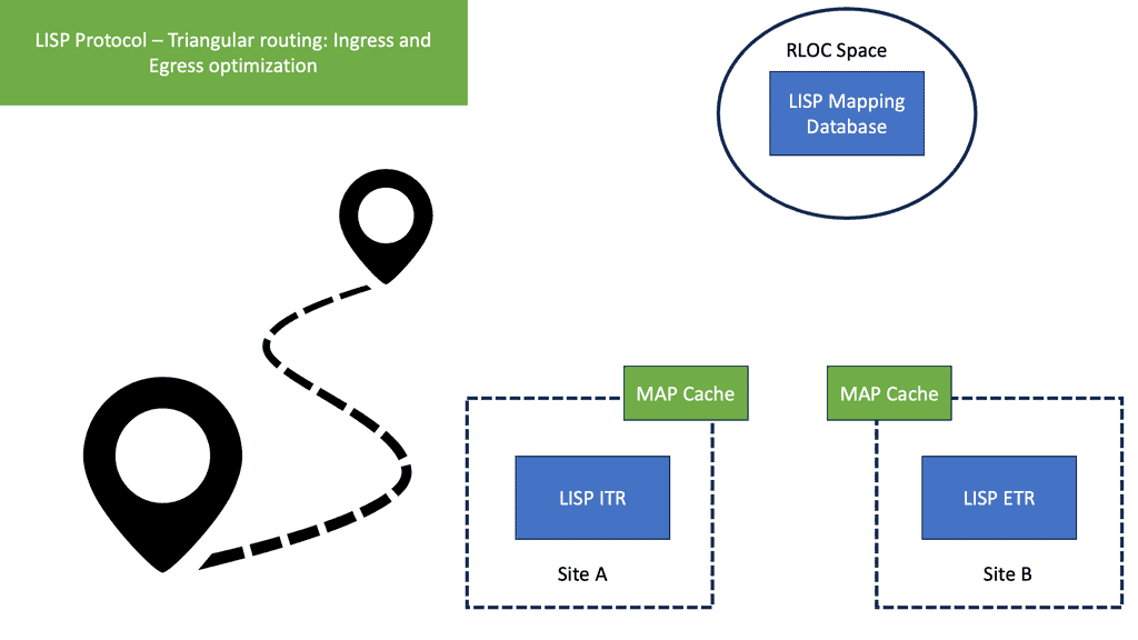
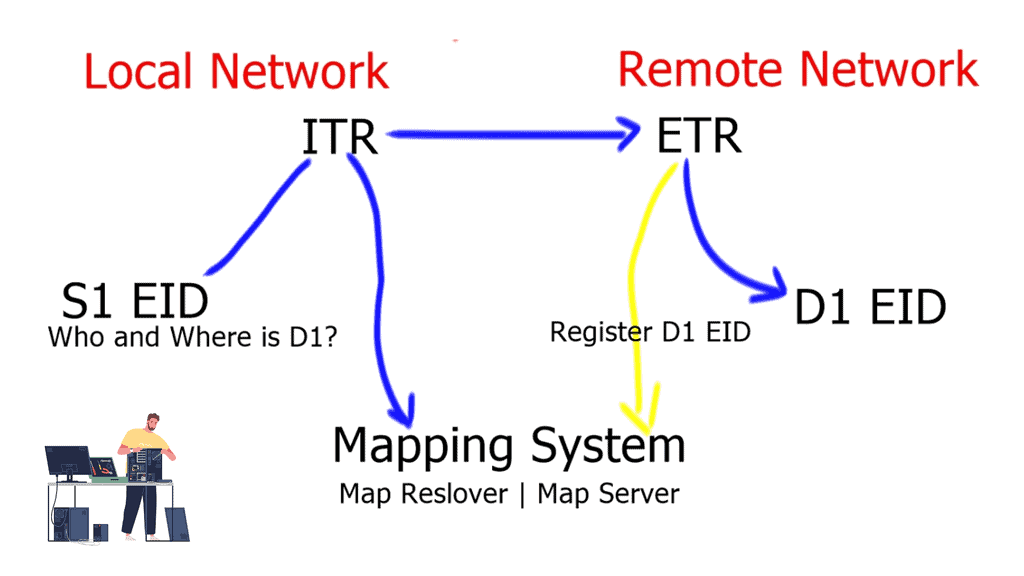
A device ( S1 ) initiates a connection and wants to communicate with another external device ( D1 ). D1 is located in a remote network. S1 will create a packet with the EID of S1 as the source IP address and the EID of D1 as the destination IP address. As the packets flow to the network’s edge on their way to D1, they are met by an Ingress Tunnel Router ( ITR ).
The ITR maps the destination EID to a destination RLOC and then encapsulates the original packet with an additional header with the source IP address of the ITR RLOC and the destination IP address of the RLOC of an Egress Tunnel Router ( ETR ). The ETR is located on the remote site next to the destination device D1.
The magic is how these mappings are defined, especially regarding VM mobility. There is no routing convergence, and any changes to the mapping systems are unknown to the source and destination hosts. We are offering complete transparency.
LISP Terminology
LISP namespaces:
LSP Name Component | LISP Protocol Description |
End-point Identifiers ( EID ) Addresses | The EID is allocated to an end host from an EID-prefix block. The EID associates where a host is located and identifies endpoints. The remote host obtains a destination the same way it obtains a normal destination address today, for example through DNS or SIP. The procedure a host uses to send IP packets does not change. EIDs are not routable. |
Route Locator ( RLOC ) Addresses | The RLOC is an address or group of prefixes that map to an Egress Tunnel Router ( ETR ). Reachability within the RLOC space is achieved by traditional routing methods. The RLOC address must be routable. |
LISP site devices:
LISP Component | LISP Protocol Description |
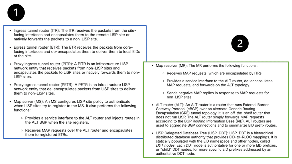
Ingress Tunnel Router ( ITR ) | An ITR is a LISP Site device that sits in a LISP site and receives packets from internal hosts. It in turn encapsulates them to remote LISP sites. To determine where to send the packet the ITR performs an EID-to-RLOC mapping lookup. The ITR should be the first-hop or default router within a site for the source hosts. |
Egress Tunnel Router ( ETR ) | An ETR is a LISP Site device that receives LISP-encapsulated IP packets from the Internet, decapsulates them, and forwards them to local EIDs at the site. An ETR only accepts an IP packet where the destination address is the “outer” IP header and is one of its own configured RLOCs. The ETR should be the last hop router directly connected to the destination. |
LISP infrastructure devices:
LISP Component Name | LISP Protocol Description |
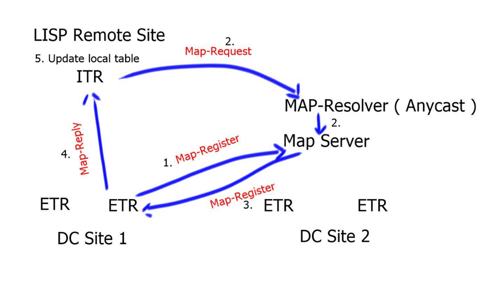
Map-Server ( MS ) | The map server contains the EID-to-RLOC mappings and the ETRs register their EIDs to the map server. The map-server advertises these, usually as an aggregate into the LISP mapping system. |
Map-Resolver ( MR ) | When resolving EID-to-RLOC mappings the ITRs send LISP Map-Requests to Map-Resolvers. The Map-Resolver is typically an Anycast address. This improves the mapping lookup performance by choosing the map-resolver that is topologically closest to the requesting ITR. |
Proxy ITR ( PITR ) | Provides connectivity to non-LISP sites. It acts like an ITR but does so on behalf of non-LISP sites. |
Proxy ETR ( PETR ) | Acts like an ETR but does so on behalf of LISP sites that want to communicate to destinations at non-LISP sites. |
VM Mobility
LISP Host Mobility
LISP VM Mobility ( LISP Host Mobility ) functionality allows any IP address ( End host ) to move from its subnet to either a) a completely different subnet, known as “across subnet,” or b) an extension of its subnet in a different location, known as “extended subnet,” while keeping its original IP address.
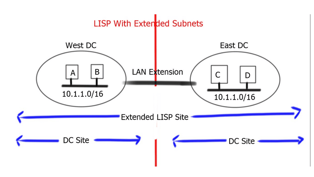
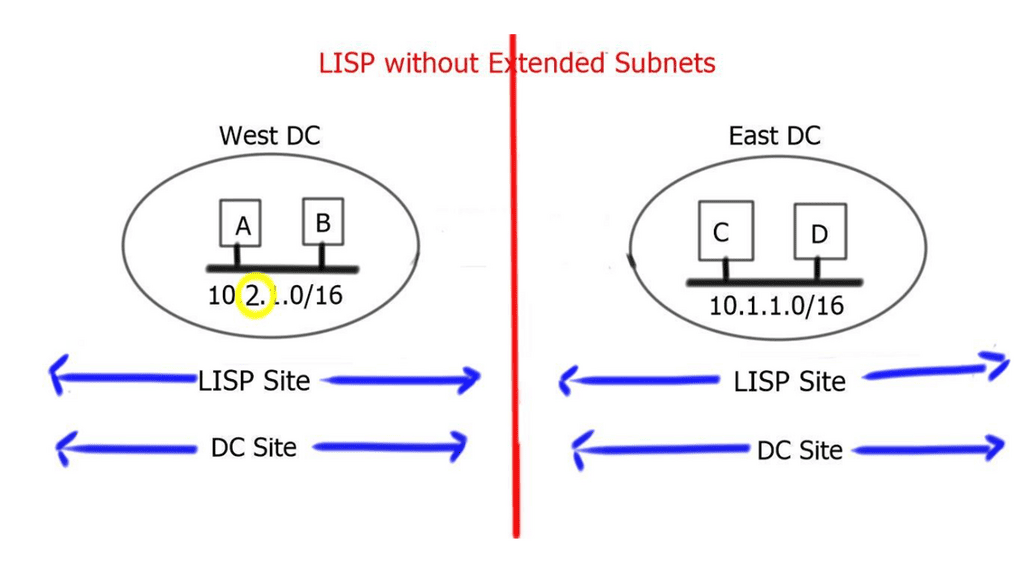
When the end host carries its own Layer 3 address to the remote site, and the prefix is the same as the remote site, it is known as an “extended subnet.” Extended subnet mode requires a Layer 2 LAN extension. On the other hand, when the end hosts carry a different network prefix to the remote site, it is known as “across subnets.” When this is the case, a Layer 2 extension is not needed between sites.
LAN extension considerations
LISP does not remove the need for a LAN extension if a VM wants to perform a “hot” migration between two dispersed sites. The LAN extension is deployed to stretch a VLAN/IP subnet between separate locations. LISP complements LAN extensions with efficient move detection methods and ingress traffic engineering.
LISP works with all LAN extensions – whether back-to-back vPC and VSS over dark fiber, VPLS, Overlay Transport Virtualization ( OTV ), or Ethernet over MPLS/IP. LAN extension best practices should still be applied to the data center edges. These include but are not limited to – End-to-end Loop Prevention and STP isolation.
A LISP site with a LAN extension extends a single site across two physical data center sites. This is because the extended subnet functionality of LISP makes two DC sites a single LISP site. On the other hand, when LISP is deployed without a LAN extension, a single LISP site is not extended between two data centers, and we end up having separate LISP sites.
LISP extended subnet
To avoid asymmetric traffic handling, the LAN extension technology must filter Hot Standby Router Protocol ( HSRP ) HELLO messages across the two data centers. This creates an active-active HSRP setup. HSRP localization optimizes egress traffic flows. LISP optimizes ingress traffic flows.
The default gateway and virtual MAC address must remain consistent in both data centers. This is because the moved VM will continue to send to the same gateway MAC address. This is accomplished by configuring the same HSRP gateway IP address and group in both data centers. When an active-active HSRP domain is used, re-ARP is not needed during mobility events.
The LAN extension technology must have multicast enabled to support the proper operation of LISP. Once a dynamic EID is detected, the multicast group IP addresses send a map-notify message by the xTR to all other xTRs. The multicast messages are delivered leveraging the LAN extension.
LISP across subnet
LISP across subnets requires the mobile VM to access the same gateway IP address, even if they move across subnets. This will prevent egress traffic triangulation back to the original data center. This can be achieved by manually setting the vMAC address associated with the HSRP group to be consistent across sites.
Proxy ARP must be configured under local and remote SVIs to correctly handle new ARP requests generated by the migrated workload. With this deployment, there is no need to deploy a LAN extension to stretch VLAN/IP between sites. This is why it is considered to address “cold” migration scenarios, such as Disaster Recovery ( DR ) or cloud bursting and workload mobility according to demands.
**Benefits of LISP**
1. Scalability: By separating the identifier from the location, LISP provides a scalable solution for network design. It allows for hierarchical addressing, reducing the size of the global routing table and enabling efficient routing across large networks.
2. Mobility: LISP’s separation of identity and location mainly benefits mobile devices. As devices move between networks, their EIDs remain constant while the RLOCs are updated dynamically. This enables seamless mobility without disrupting ongoing connections.
3. Multihoming: LISP allows a device to have multiple RLOCs, enabling multihoming capabilities without complex network configurations. This ensures redundancy, load balancing, and improved network reliability.
4. Security: LISP provides enhanced security features, such as cryptographic authentication and integrity checks, to ensure the integrity and authenticity of the mapping information. This helps mitigate potential attacks, such as IP spoofing.
**Applications of LISP**
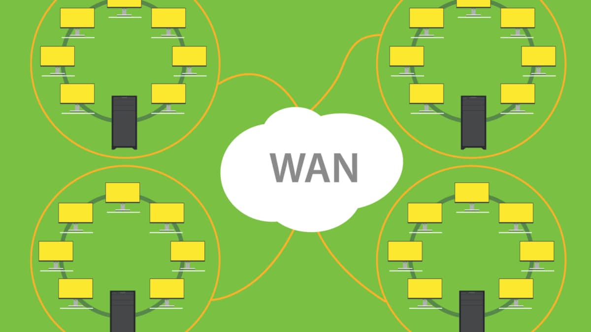
1. Data Center Interconnection: LISP can interconnect geographically dispersed data centers, providing efficient and scalable communication between locations.
2. Internet of Things (IoT): With the exponential growth of IoT devices, LISP offers an efficient solution for managing these devices’ addressing and communication needs, ensuring seamless connectivity in large-scale deployments.
3. Content Delivery Networks (CDNs): LISP can optimize content delivery by allowing CDNs to cache content closer to end-users, reducing latency and improving overall performance.
Closing Points: LISP and VM Mobility
LISP is a network architecture and protocol that separates the two functions of IP addresses: identifying endpoints and routing traffic. By doing so, it allows for more efficient routing and a reduction in the complexity of network management. This separation is fundamental to enabling VM mobility, as it allows VMs to maintain consistent identities even as their physical locations change.
One of the primary benefits of LISP VM Mobility is the enhanced flexibility it provides. Businesses can move VMs across different data centers or cloud environments without having to reconfigure their network settings. This capability is particularly beneficial for disaster recovery scenarios, load balancing, and maintenance operations. Additionally, LISP VM Mobility can lead to cost savings by optimizing resource utilization and reducing the need for redundant infrastructure.
To implement LISP VM Mobility, organizations need to ensure that their network infrastructure supports the LISP protocol. This may involve updating network equipment and software to be compatible with LISP. Additionally, IT teams should be trained to manage and troubleshoot LISP-enabled environments effectively. By taking these steps, businesses can harness the full potential of LISP VM Mobility to drive innovation and efficiency.
Despite its advantages, LISP VM Mobility is not without challenges. Organizations must carefully plan the transition to ensure compatibility and minimize disruptions. Security is another critical consideration, as the dynamic nature of VM mobility can introduce new vulnerabilities. Implementing robust security measures, such as encryption and access controls, is essential to safeguarding data as it moves across networks.