WAN Design Requirements

DMVPN

NETWORK INSIGHT · ENGINEERING GUIDE

DMVPN: Designing and Investigating Dynamic VPN Overlays

Dynamic Multipoint VPN (DMVPN) combines multipoint GRE, Next Hop Resolution Protocol (NHRP), IPsec and dynamic routing to build scalable VPN connectivity across an underlying IP network.

The engineering challenge is not simply creating a secure tunnel. A DMVPN deployment must dynamically discover remote endpoints, establish the appropriate tunnel path, maintain routing information and provide efficient communication between sites as the network grows.

This guide moves beyond configuration syntax and examines DMVPN as an operational system. You will follow the relationship between the underlay and overlay, observe how NHRP provides endpoint resolution, investigate how spoke-to-spoke connectivity develops, and correlate routing, tunnel and security evidence when troubleshooting the network.

01 · SEE DMVPN Architecture Understand the underlay, overlay, hub, spokes and core DMVPN components.
02 · OBSERVE NHRP & Tunnel Evidence Examine mappings, tunnel state, routing information and security evidence.
03 · INVESTIGATE Spoke-to-Spoke Paths Follow NHRP redirect and resolution as traffic moves toward a direct path.
04 · OPERATE Routing & Resiliency Correlate routing, IPsec and failure evidence to verify network health.
Investigation Focus
Follow the evidence

The interactive sections turn DMVPN behaviour into an engineering investigation: identify the path, inspect the evidence, determine what changed and verify the resulting network state.

Engineering Objective

By the end of the guide, you should be able to explain how DMVPN forms and optimises its overlay, identify the evidence created by NHRP and IPsec, distinguish hub-and-spoke from direct spoke-to-spoke forwarding, and use multiple observations to isolate a DMVPN failure.

The interactive sections are designed as engineering exercises rather than demonstrations. Each stage builds on the previous one so that architecture, evidence, investigation and operational verification form one continuous learning path.
ENGINEERING GUIDE · 01 — SEE

Understand the DMVPN Architecture

Start with the dependency chain. DMVPN is not a single protocol: the underlay, mGRE, NHRP, IPsec and routing functions each solve a different engineering problem. Before troubleshooting traffic, establish which layer is responsible for connectivity, discovery, security, routing and forwarding.

UNDERLAY mGRE NHRP IPsec ROUTING
ENGINEERING EVIDENCE · SECTION 01

SEE — DMVPN Architecture

Before investigating a DMVPN failure, understand how the underlay, mGRE, NHRP, IPsec and routing functions fit together to create the overlay.

DMVPN Architecture Stack
UNDERLAY
IP connectivity between the physical / NBMA endpoints
REACHABILITY
mGRE
Multipoint tunnel framework for dynamic destinations
OVERLAY
NHRP
Dynamic discovery and logical-to-NBMA mapping
CONTROL
IPsec
Encryption and protection of overlay traffic
SECURITY
ROUTING
Destination reachability and path selection
CONTROL
Underlay

The underlying IP network provides basic reachability between DMVPN routers. If the underlay cannot reach the required peer, the overlay cannot form correctly.

From Infrastructure To Application
01
UNDERLAY
IP / NBMA reachability
›
02
mGRE
Multipoint overlay
›
03
NHRP
Peer discovery
›
04
IPsec
Traffic protection
›
05
ROUTING
Path selection
›
06
APPLICATION
End-to-end traffic
DMVPN Traffic Models
PHASE 1

Hub-and-Spoke

Traffic remains logically centred on the hub. The hub provides the central connectivity point for the spokes.

PHASE 2

Spoke-to-Spoke

Spokes can dynamically establish direct connectivity when the routing and NHRP information support the destination.

PHASE 3

Hub-Initiated

The hub can participate in redirecting traffic toward a more efficient spoke-to-spoke path.

Engineering View

DMVPN should not be investigated as a single protocol. A tunnel can appear operational while NHRP mappings, IPsec security associations or routing information are incorrect.

The investigation therefore follows the dependency chain: Underlay → mGRE → NHRP → IPsec → Routing → Forwarding.

ENGINEERING QUESTIONS
Can the underlay reach the peer?
Does NHRP know where the peer is?
Are IPsec security associations present?
Is routing selecting the expected path?
Does forwarding match the design?
ENGINEERING EVIDENCE · DMVPN ARCHITECTURE

SEE — DMVPN Architecture

Interrogate the DMVPN dependency chain. Select a layer to see what it does, what evidence proves it is working, and what depends on it.
ARCHITECTURE ONLINE
DMVPN Dependency Stack
01
UNDERLAY
Physical/IP transport and NBMA reachability
REACHABLE
02
mGRE
Multipoint tunnel framework
UP
03
NHRP
Logical tunnel-to-NBMA peer mapping
MAPPED
04
IPsec
Protection of tunnel traffic
SA UP
05
ROUTING
Prefix reachability and path selection
VALID
Engineering Dependency Chain
UNDERLAY › mGRE › NHRP › IPsec › ROUTING
LAYER 01 · TRANSPORT

Underlay Reachability

The underlay provides IP reachability between the physical or NBMA endpoints. DMVPN cannot establish useful overlay behaviour if the transport network cannot reach the required peers.

Function Transport
Example 198.51.100.11
Evidence IP route / ping
Failure boundary Peer unreachable
DMVPN Operating Model
Phase 1 · Hub-and-Spoke Spokes primarily communicate through the hub.
Phase 2 · Spoke-to-Spoke Spokes can establish direct dynamic paths.
Phase 3 · Hub-Assisted Hub redirects traffic towards an optimized peer path.
Evidence Command
show ip route 198.51.100.1
Selected Layer Depends On
The underlay is the foundation. Higher DMVPN functions ultimately depend on transport reachability.
IP Reachability NBMA Transport
What This Layer Does Not Prove
A reachable underlay does not prove that the DMVPN tunnel, NHRP mappings, IPsec SAs or routing are correct.
mGRE NHRP IPsec Routing
ENGINEERING GUIDE · 02 — DISCOVER

How NHRP Builds Dynamic Peer Knowledge

Once the tunnel framework exists, DMVPN needs a way to associate logical tunnel addresses with real NBMA destinations. NHRP provides that discovery and mapping function, allowing spokes and the NHS to build the peer information required by the overlay without turning NHRP itself into the routing protocol.

REGISTRATION NHS / NHC MAPPING RESOLUTION
ENGINEERING EVIDENCE · SECTION 02

DISCOVER — NHRP and Dynamic Peer Mapping

mGRE provides the multipoint tunnel framework, but it does not tell a DMVPN router where another peer exists on the underlay. NHRP provides the discovery and mapping mechanism that connects the logical tunnel address with the peer's NBMA address.

NHRP Discovery Sequence
01
Spoke Registration
The spoke tells the NHS where it can be reached.
02
NHRP Mapping
The hub builds dynamic peer information.
03
Resolution Request
The destination peer's location is requested.
04
Resolution Reply
Logical and NBMA information is returned.
Spoke Registration
REGISTER
SPOKE 1
NHC
HUB
NHS
SPOKE 2
NHC
NHRP EVENT
The spoke registers its tunnel address and NBMA address with the NHS.
Dynamic NHRP Information

NHRP Mapping View

DEVICE ROLE TUNNEL NBMA STATE
HUB NHS 172.16.100.1 198.51.100.1 LOCAL
SPOKE 1 NHC 172.16.100.11 198.51.100.11 REGISTERED
SPOKE 2 NHC 172.16.100.12 198.51.100.12 PENDING

Engineering Interpretation

NHRP is not the routing protocol that determines which destination network should be used. Its role is to provide the information required to reach another DMVPN peer by relating a logical tunnel address to an NBMA address.

This makes NHRP an important dependency when investigating dynamically established DMVPN connectivity.

CLI EVIDENCE
show ip nhrp
show ip nhrp nhs
show dmvpn
show ip interface tunnel 0
ENGINEERING CHECKPOINT
Is the spoke registered with the correct NHS?
Does the NHRP table contain the expected NBMA mapping?
Can the discovered peer be reached across the underlay?
CORE IDEA
NHRP discovers where a DMVPN peer lives on the underlay.
Routing still determines destination reachability and path selection.
ENGINEERING EVIDENCE · NHRP DISCOVERY

DISCOVER — Dynamic Peer Mapping

Step through the NHRP control-plane sequence and watch how a DMVPN peer moves from registration to a usable logical-to-NBMA mapping.
NHRP CONTROL PLANE
Live NHRP Discovery Sequence
The hub acts as the NHS. Spokes register their tunnel/NBMA information and can subsequently resolve dynamic peer information.
SPOKE 1
NHC
172.16.100.11
198.51.100.11
HUB
NHS
172.16.100.1
198.51.100.1
SPOKE 2
NHC
172.16.100.12
198.51.100.12
INITIAL NHRP STATE
EVENT 01 · REGISTRATION
Spoke 1 sends NHRP registration information towards the NHS, advertising its logical tunnel address and NBMA address.
Control-Plane Events
01
Spoke Registration NHC registers its logical and NBMA information with the NHS.
02
NHRP Mapping The NHS records the logical-to-NBMA relationship.
03
Resolution Request A spoke requests information for a dynamic peer.
04
Resolution Reply The requested peer mapping becomes available.
NHRP Mapping Table
Node Logical NBMA State
HUB 172.16.100.1 198.51.100.1 LOCAL
SP1 172.16.100.11 198.51.100.11 REGISTERED
SP2 172.16.100.12 198.51.100.12 PENDING
Engineering Interpretation

NHRP is not a routing protocol. Its role here is to provide the information needed to map a logical DMVPN peer to its NBMA transport address.

Operational Evidence
show ip nhrp show ip nhrp nhs show dmvpn show ip interface tunnel 0
What The Mapping Tells You
Logical address → NBMA address
The mapping establishes how a DMVPN logical peer relates to its underlying transport endpoint. It does not, by itself, prove that IPsec is established or that the routing table contains the correct destination path.
ENGINEERING GUIDE · 03 — PROTECT

How IPsec Protects the DMVPN Overlay

NHRP can identify a peer, but discovery alone does not provide security. IPsec establishes the protection required for DMVPN traffic, securing the encapsulated overlay between peers. A tunnel interface being operational is therefore not sufficient evidence that encrypted traffic is successfully passing.

IKE AUTHENTICATION IPsec SA ESP ENCRYPTION
ENGINEERING EVIDENCE · SECTION 03

PROTECT — IPsec Security

NHRP can identify where a DMVPN peer exists, but discovery does not provide confidentiality or integrity. IPsec supplies the security layer that protects DMVPN traffic as it crosses the underlying network.

Security Establishment Sequence
01
IKE / Negotiation
Security parameters are negotiated between the peers.
02
Authentication
Each peer verifies the identity of the other side.
03
IPsec SA
The negotiated security association is established.
04
GRE Protection
Overlay traffic is protected before entering the underlay.
05
Protected Transport
The secured packet traverses the underlying IP network.
IKE / Security Negotiation
NEGOTIATE
DMVPN PEER A
IPsec PEER
DMVPN PEER B
IPsec PEER
UNDERLAY / NBMA NETWORK
IPSEC PROTECTED
SECURITY EVENT
The peers negotiate the parameters required to establish protected communication.
What The Router Should Show

Security Association Evidence

PEER
198.51.100.12
STATE
ESTABLISHED
PROTOCOL
ESP

Engineering Interpretation

A working tunnel interface does not by itself prove that protected traffic can pass. IPsec security associations must be established and traffic must be processed by the correct security policy.

When troubleshooting, separate the questions: Is the peer reachable? Is the security association established? Are packets actually being encrypted and decrypted?

CLI EVIDENCE
show crypto isakmp sa
show crypto ipsec sa
show crypto session
ENGINEERING EVIDENCE · IPSEC SECURITY

PROTECT — IPsec Security

Follow the security establishment process from IKE negotiation through an operational IPsec SA and protected DMVPN traffic.

SECURITY STANDBY
Live Security Path
PEER A ↔ PEER B
STAGE 1 · IKE
A
DMVPN PEER A
198.51.100.11
B
DMVPN PEER B
198.51.100.12
UNDERLAY / NBMA TRANSPORT
NBMA · 198.51.100.11 → 198.51.100.12
IKE negotiation begins The peers establish the security negotiation required before protected traffic can be exchanged.
Security Establishment
CLICK TO INSPECT
SA Telemetry
LIVE STATE
Peer
198.51.100.12
State
NEGOTIATING
Protocol
IKE
Encrypt
0 pkts
Decrypt
0 pkts
Protection
NOT ACTIVE
Selected Stage Evidence

IKE establishes the negotiation context. At this point, an operational IPsec SA has not yet been demonstrated.

R1# show crypto isakmp sa
Engineering Interpretation

A DMVPN tunnel interface being operational does not by itself prove that encrypted traffic is successfully passing between peers.

ENGINEERING PRINCIPLE: NHRP identifies the peer's NBMA information; IPsec protects the traffic. When troubleshooting, separate peer discovery, security-association establishment and actual encrypted packet counters rather than treating “tunnel up” as proof of end-to-end operation.
ENGINEERING GUIDE · 04 — ROUTE

How Routing Determines the Overlay Path

DMVPN provides the overlay connectivity, but routing protocols determine which destination prefixes are reachable and which path is preferred. EIGRP, OSPF and BGP can operate across the overlay, each applying its own path-selection logic.

EIGRP OSPF BGP BEST PATH CEF
ENGINEERING EVIDENCE · SECTION 04

ROUTE — Routing Across the DMVPN Overlay

DMVPN provides the overlay connectivity, but routing determines which destination prefixes are reachable and which path the router prefers. EIGRP, OSPF and BGP can operate across the overlay, with the routing design influencing how traffic moves between spokes and hubs.

Select A Routing Model
EIGRP
Fast convergence and native Cisco integration.
IGP
OSPF
Link-state routing across the overlay.
IGP
BGP
Policy-driven routing and path control.
EGP
Route Decision View

EIGRP Routing Model

EIGRP can exchange routes across the DMVPN overlay and is commonly used in Cisco-centric DMVPN designs. Its metrics and next-hop behaviour influence the selected path.

Metric
LOWER
Feasibility
CHECK
Next Hop
OVERLAY
Split Horizon
DESIGN
Candidate Paths
ROUTE INSTALLED
PATH A · DIRECT SPOKE
Via Tunnel0 · metric 90
→
10.40.40.0/24
Preferred path
PATH B · HUB
Via Tunnel0 · metric 120
→
10.40.40.0/24
Alternate path
PATH C · BACKUP
Via secondary path
→
10.40.40.0/24
Standby
Select a candidate path to inspect the routing decision.

Engineering Interpretation

A DMVPN tunnel being operational does not mean that the expected route will be installed. The overlay provides connectivity between routers; the routing protocol decides which prefixes are reachable and which path should be preferred.

Investigation Question

If the destination prefix exists but traffic takes the wrong path, investigate the routing information before assuming that the DMVPN tunnel itself is broken.

CLI EVIDENCE
show ip route
show ip route 10.40.40.0
show ip protocols
show ip cef 10.40.40.0

Following the Packet Through the Overlay

A DMVPN tunnel is not the packet itself. It is the transport framework that allows one router to carry an original IP packet across an underlying network. To understand forwarding behaviour, separate the inner packet from the DMVPN overlay and the underlay transport.

Consider a packet travelling from a host behind Spoke 1 to a host behind Spoke 2. The original packet might have the source 10.10.10.10 and destination 10.40.40.40. Those addresses describe the actual communication. They are not replaced simply because the packet enters the DMVPN tunnel.

Source Host → mGRE Tunnel → IPsec Protection → Underlay → Remote Peer → Destination

The Inner Packet

The original IP packet contains the addresses used by the overlay routing decision and, ultimately, the destination host. For example:

# Original IP packet
SRC       10.10.10.10
DST       10.40.40.40
PROTOCOL  IP

Spoke 1 uses its routing and forwarding information to determine that the destination prefix is reachable through the DMVPN overlay. The packet is therefore handed towards the tunnel interface rather than being forwarded directly using the physical underlay interface.

mGRE Creates the Overlay Transport

mGRE provides the multipoint tunnel framework. Instead of requiring a separate permanent tunnel interface for every possible peer, a DMVPN router can use a single multipoint GRE tunnel to support dynamically discovered peers.

The important engineering distinction is that mGRE provides the tunnel mechanism, while NHRP provides the peer discovery and logical-to-NBMA mapping information required to reach dynamic peers.

Inner

Original source and destination addresses remain associated with the actual IP communication.

Overlay

mGRE carries the original packet across the DMVPN tunnel infrastructure.

Underlay

The transport network carries the encapsulated traffic between the DMVPN peers.

IPsec Protects the Tunnel Traffic

After the tunnel traffic has been constructed, IPsec provides the security layer. Depending on the deployment, the GRE traffic is protected using IPsec security associations and ESP.

This creates an important troubleshooting boundary. A tunnel interface can appear operational while the required IPsec security association is missing or while protected traffic is not being successfully encrypted and decrypted.

Engineering Evidence

Tunnel up does not automatically mean traffic is working. Validate the tunnel, NHRP state, IPsec security associations, routing information and forwarding behaviour independently.

The Underlay Sees the Outer Transport

Once the packet has been encapsulated and protected, the underlay network forwards the resulting transport traffic. The underlay is concerned with reaching the remote DMVPN peer rather than understanding the final application destination inside the overlay.

# Example outer transport addresses
OUTER SRC  198.51.100.11
OUTER DST  198.51.100.12
PROTOCOL   IPsec / ESP

This distinction is extremely useful during troubleshooting. If the underlay cannot reach 198.51.100.12, the overlay cannot carry the packet regardless of whether the routing configuration itself is correct.

Decapsulation at the Remote Peer

At the remote DMVPN router, the process is reversed. The protected transport is received and processed by IPsec. The tunnel encapsulation is then removed, exposing the original IP packet.

The remote router can then perform normal IP forwarding towards 10.40.40.40. The final destination therefore sees the original IP communication rather than the intermediate NBMA transport addresses used by the DMVPN infrastructure.

What Each Layer Actually Knows

Overlay Routing

Determines how the destination prefix is reached through the DMVPN overlay.

IPsec

Protects the tunnel traffic and maintains the required security associations.

Underlay

Provides transport reachability between the physical/NBMA endpoints.

Engineering Principle

Follow the packet, not just the tunnel. When a DMVPN path fails, determine which layer can no longer carry the packet. A working underlay does not prove NHRP is correct. An established NHRP mapping does not prove IPsec is protecting traffic. An established IPsec SA does not prove the routing table contains the expected destination path.

Evidence to Collect

The data plane can be correlated with the control-plane state using a small set of operational commands:

# Forwarding decision
show ip cef 10.40.40.40

# Tunnel state and counters
show interfaces tunnel 0

# NHRP peer mappings
show ip nhrp

# IPsec protection and packet counters
show crypto ipsec sa

These outputs should be interpreted together. The goal is not simply to prove that individual commands return output, but to establish a continuous forwarding chain from the source host to the destination.

ENGINEERING EVIDENCE · OVERLAY ROUTING

ROUTE — Routing Across the DMVPN Overlay

Compare candidate paths and see how the routing protocol determines which overlay path becomes the forwarding decision.

ROUTE ANALYSIS READY
Candidate Route Topology
10.40.40.0/24
R1
SOURCE
10.10.10.0/24
RR
RR1
AS65001
R4
DESTINATION
10.40.40.0/24
Candidate paths discovered The same destination prefix is visible through multiple overlay paths. The routing process must select the usable best path.
Routing Protocol
SELECT MODEL
Candidate Paths
CLICK TO INSPECT
Decision Telemetry
LIVE ANALYSIS
Protocol
EIGRP
Selected
PATH A
Destination
10.40.40.0
FIB State
CANDIDATES
Routing Evidence

The routing table contains multiple candidate paths to the same destination. The selected path is the route that will be installed for forwarding.

R1# show ip route 10.40.40.0
R1# show ip cef 10.40.40.0
Engineering Interpretation

DMVPN provides the overlay connectivity. The routing protocol determines which destination prefix is reachable and which path should be preferred.

ENGINEERING PRINCIPLE: A healthy DMVPN tunnel does not automatically mean the correct route is being used. Separate overlay connectivity from route selection, then verify the installed RIB and CEF forwarding decision.
ENGINEERING GUIDE · 05 — FORWARD

FORWARD — Follow the DMVPN Data Plane

Once the overlay is built, the real engineering question is simple: how does an actual packet travel? Follow the original IP packet from the source host through the DMVPN tunnel, across the underlay, and back into the remote network. This separates the inner packet, overlay tunnel, IPsec protection, and underlay transport so failures can be isolated to the correct layer.

INNER PACKET mGRE IPsec UNDERLAY DECAPSULATION
ENGINEERING EVIDENCE · SECTION 05

FORWARD — DMVPN Data Plane & Packet Flow

Once the overlay is established and routing has selected a path, the next question is simple: what actually happens to the packet? The DMVPN data plane combines the original IP packet, the tunnel overlay, IPsec protection and the underlay transport. Understanding these layers makes it possible to identify exactly where forwarding succeeds or fails.

→
Engineering principle The original packet is not replaced by the DMVPN transport. It is encapsulated, protected and carried across the underlay, then decapsulated at the remote endpoint.
01
Source Host Original IP packet is generated.
02
Spoke Routing selects Tunnel0.
03
mGRE Overlay encapsulation is added.
04
IPsec Tunnel traffic is protected.
05
Underlay NBMA transport forwards it.
06
Remote Spoke Traffic is decapsulated.
Packet Construction

One packet, multiple forwarding views

The endpoint application creates an ordinary IP packet. The DMVPN tunnel then provides the transport framework around that packet. mGRE identifies the tunnel overlay while IPsec protects the resulting tunnel traffic before it crosses the physical network.

INNER 10.10.10.10 → 10.40.40.40
TUNNEL Spoke1 Tunnel0 → Spoke2 Tunnel0
OUTER 198.51.100.11 → 198.51.100.12
Forwarding Layers

What each layer actually sees

IP
Inner IP The original source and destination prefixes used by the overlay routing decision.
GRE
mGRE Overlay Provides the tunnel framework used to carry the original packet between DMVPN peers.
SEC
IPsec Protection Protects the tunnel traffic before it enters the physical underlay.
WAN
Underlay Forwards the transport using the outer NBMA addresses.
Remote Processing

Decapsulation restores the original forwarding context

At the remote DMVPN peer, the protected transport is processed in the reverse direction. IPsec protection is removed, the mGRE encapsulation is removed, and the original IP packet becomes available for normal forwarding toward its destination. This distinction is critical: the physical network forwards the outer transport, while the DMVPN overlay forwards the inner destination prefix.

CEF Decision

Confirm which interface and next-hop the router selected for the destination prefix.

show ip cef 10.40.40.0

Tunnel State

Confirm the tunnel interface is operational and carrying the expected traffic.

show interfaces tunnel 0

IPsec Counters

Confirm encryption and decryption counters are increasing when traffic is generated.

show crypto ipsec sa
Engineering interpretation

If the underlay is reachable but the destination cannot be forwarded, do not treat the problem as a single “DMVPN tunnel failure.” Separate the investigation into the layers: underlay transport → tunnel encapsulation → IPsec protection → overlay routing → forwarding. The point at which the packet stops progressing identifies the most useful next piece of evidence.

ENGINEERING EVIDENCE · SECTION 05

FORWARD — Follow the DMVPN Data Plane

Trace one packet from the source host to the remote destination. Select each stage to see which address, header and forwarding function is active at that point in the journey.
DATA PLANE READY
Live Packet Journey
PACKET
01
SOURCE Original IP packet
02
mGRE Overlay encapsulation
03
IPsec Protected transport
04
UNDERLAY Outer NBMA forwarding
05
DESTINATION Decapsulation + delivery
Source Host
10.10.10.10
→
Remote Host
10.40.40.40

Original IP Packet

The source creates the original IP packet. At this point there is no DMVPN tunnel header and the destination is the final host.

Stage SOURCE
Source 10.10.10.10
Destination 10.40.40.40
Forwarding HOST
Engineering Evidence
show ip cef 10.40.40.40 show interfaces tunnel 0 show crypto ipsec sa
Packet Header Inspection INNER
Inner IP
SRC 10.10.10.10
DST 10.40.40.40
DMVPN Overlay
Tunnel0
mGRE / NHRP peer
Outer Transport
NBMA 198.51.100.11
→ 198.51.100.12
STEP 01
Original Packet Host creates IP traffic.
STEP 02
mGRE Overlay encapsulation begins.
STEP 03
IPsec GRE traffic is protected.
STEP 04
Underlay Outer addresses are forwarded.
STEP 05
Decapsulation Remote peer removes tunnel layers.
RESULT
Forwarded Original packet reaches destination.
NETWORK INSIGHT · INTERACTIVE ENGINE

DMVPN — Phase 3 Explorer

Explore DMVPN Phase 3, follow the NHRP Redirect and Resolution process, and see how the resulting spoke-to-spoke path is used.
Phase 3 Network Topology
PHASE 3 · NHRP REDIRECT
Spoke 1
DMVPN SPOKE
Hub
NHRP NHS
Spoke 2
DMVPN SPOKE
NHRP REDIRECT
STEP 1 / 4
Initial traffic crosses the Hub
Spoke 1 initially sends traffic toward Spoke 2 through the DMVPN hub.
Phase 3 Detail
NHRP · OPTIMIZATION
Phase 3 — NHRP Redirect
The hub can signal that traffic between two spokes can use a more direct path.
Initial Path Spoke 1 → Hub → Spoke 2
NHRP Redirect + Resolution
Direct Path Yes
NHRP Control Plane
REGISTRATION · RESOLUTION
NHRP · CONTROL PLANE
HUB
NHRP NHS
SPOKE 1
NHRP CLIENT
SPOKE 2
NHRP CLIENT
REGISTRATION
REGISTRATION
REMOTE MAPPING / RESOLUTION
Selected Object
NHRP
NHRP Control Plane
NHRP allows DMVPN spokes to register their tunnel information and discover remote spoke mappings.
Function Peer discovery
Server Hub / NHS
Security IPsec
DMVPN Packet Encapsulation
GRE · IPSEC · UNDERLAY
ORIGINAL IP PACKET
Spoke 1
SOURCE
Spoke 2
DESTINATION
Original IP Packet
Source → Destination
GRE / mGRE
Overlay tunnel encapsulation
IPsec
Authentication / encryption protection
Underlay / Transport
Physical or routed IP transport
The original packet is carried through the DMVPN overlay and protected by IPsec.
Encapsulation Detail
PACKET FLOW
Original IP Packet
The original application packet is generated by the source network before tunnel encapsulation.
Layer Payload
Technology IP
Purpose Original traffic
ENGINEERING GUIDE · 06 — INVESTIGATE

INVESTIGATE — DMVPN Failure Workflow

A DMVPN failure should be investigated as a dependency chain, not as a single tunnel problem. Work from the underlay through mGRE, NHRP, IPsec, routing and finally forwarding to isolate the first broken layer.

Underlay mGRE NHRP IPsec Routing Forwarding
ENGINEERING EVIDENCE · SECTION 06

INVESTIGATE — DMVPN Failure Workflow

Troubleshooting DMVPN becomes much easier when the investigation follows the dependency chain established throughout this guide. Instead of treating “the tunnel is down” as the diagnosis, identify the first layer that has failed and prove it with operational evidence.

!
The first failed dependency is usually more valuable than the final symptom.

A missing route may be caused by routing policy, an unresolved NHRP peer, an unavailable IPsec security association, or a broken underlay. The correct troubleshooting sequence prevents a downstream symptom from being mistaken for the root cause.

Start With the Dependency Chain

DMVPN is not a single protocol. It is a collection of functions operating together. Each layer depends on the layers beneath it, so investigation should normally move from basic transport reachability toward the final forwarding decision.

01

Underlay

Confirm that the NBMA transport addresses are reachable before investigating the overlay.

show ip route
02

mGRE

Verify that Tunnel0 is operational and that the tunnel interface has the expected state and addressing.

show interfaces tunnel 0
03

NHRP

Check whether logical tunnel peers are correctly registered and mapped to their NBMA addresses.

show ip nhrp
04

IPsec

Confirm that the required security associations exist and that protected traffic is being encrypted and decrypted.

show crypto ipsec sa
05

Routing

Determine whether the destination prefix exists and whether the expected path has been selected.

show ip route
06

Forwarding

Verify that the selected route produces the expected CEF forwarding decision and next hop.

show ip cef

Common Failure Signatures

The same user-visible symptom can originate from different layers. The objective is therefore to correlate the symptom with the control-plane and forwarding evidence underneath it.

Underlay Unreachable

The NBMA address of the remote peer cannot be reached. NHRP, IPsec and overlay routing may subsequently appear broken because their transport dependency is unavailable.

NHRP Mapping Missing

The tunnel framework may exist, but the required logical-to-NBMA peer information is absent or incomplete. Dynamic peer communication can therefore fail.

IPsec SA Missing

Peer discovery may succeed while protected traffic still fails because the required security association has not been established or is not passing traffic.

Routing Mismatch

The DMVPN overlay can be operational while the routing process selects an unexpected path, rejects a prefix, or fails to install the destination in the forwarding table.

Evidence Before Diagnosis

A strong troubleshooting process does not begin by changing configuration. First establish what the network believes is happening. Then compare that evidence with the expected dependency state.

Peer and Tunnel Evidence

Establish whether the transport, tunnel and NHRP control plane agree about the remote peer.

! Underlay
show ip route 198.51.100.12
ping 198.51.100.12

! DMVPN / NHRP
show dmvpn
show ip nhrp

Security and Routing Evidence

Once peer reachability is established, determine whether protected transport and route installation are functioning.

! IPsec
show crypto ipsec sa
show crypto session

! Routing / forwarding
show ip route 10.40.40.0
show ip cef 10.40.40.0

The Correct Troubleshooting Order

The investigation should move from the dependency that everything else requires toward the final forwarding decision. Skipping directly to routing or application symptoms can produce misleading conclusions.

UNDERLAY
›
mGRE
›
NHRP
›
IPsec
›
ROUTING
›
FORWARDING

Engineering Conclusion

A DMVPN investigation should move from reachability → discovery → security → routing → forwarding. Each layer answers a different question. Underlay evidence proves transport reachability. NHRP proves peer discovery and mapping. IPsec proves protected transport. Routing proves the destination path. CEF and forwarding evidence prove what the router will actually do with the packet.

ENGINEERING EVIDENCE · DMVPN INCIDENT LAB

INVESTIGATE — DMVPN Failure Workflow

Inject a controlled DMVPN failure, collect evidence from each dependency layer, and identify the first failed component rather than treating the final symptom as the root cause.

NO INCIDENT
Live DMVPN Incident
CONTROL PLANE + DATA PLANE
No active failure
Select a failure scenario, inject it into the topology, then investigate the dependency chain.
S1
SPOKE 1
198.51.100.11
READY
H
HUB / NHS
198.51.100.1
READY
S2
SPOKE 2
198.51.100.12
READY
FAILURE DETECTED
Engineering target: determine which dependency fails first.
Fault Injection
SELECT INCIDENT
Evidence Collection
SEQUENTIAL
1
Underlay
WAIT
2
mGRE Tunnel
WAIT
3
NHRP
WAIT
4
IPsec
WAIT
5
Routing
WAIT
6
Forwarding
WAIT
Diagnosis
ROOT CAUSE
INVESTIGATION READY

No diagnosis yet

Inject a fault and run the investigation to correlate the evidence.

R1# show dmvpn
```
☕
Support Network Insight
Help support independent engineering guides, interactive networking tools, and future learning labs.
Support Network Insight ```
GRE over IPsec

Point-to-Point Generic Routing Encapsulation over IP Security

Point-to-Point Generic Routing Encapsulation over IP Security

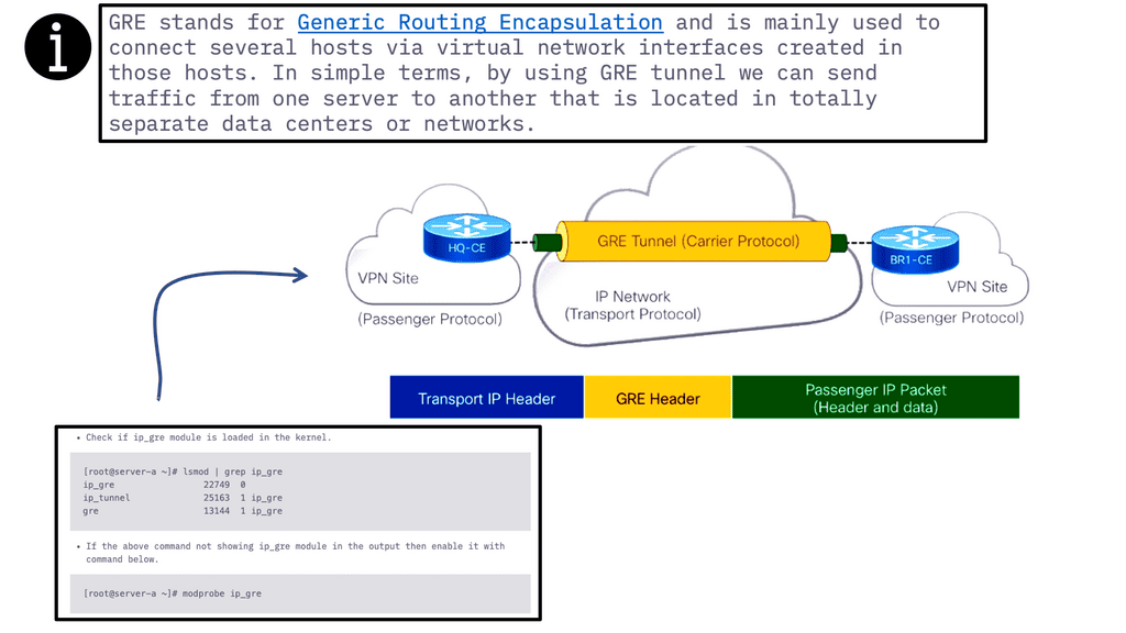
Generic Routing Encapsulation (GRE) is a widely used encapsulation protocol in computer networking. It allows the transmission of diverse network protocols over an IP network infrastructure. In this blog post, we'll delve into the details of the GRE and its significance in modern networking.

GRE acts as a tunneling protocol, encapsulating packets from one network protocol within another. By creating a virtual point-to-point link, it facilitates the transmission of data across different network domains. This enables the interconnection of disparate networks, making GRE a crucial tool for securely building virtual private networks (VPNs) and connecting remote sites.

P2P GRE is a tunneling protocol that allows the encapsulation of various network layer protocols within IP packets. It provides a secure and reliable method of transmitting data between two points in a network. By encapsulating packets in IP headers, P2P GRE ensures data integrity and confidentiality.

IP Security (IPsec) plays a crucial role in enhancing the security of P2P GRE tunnels. By leveraging cryptographic algorithms, IPsec provides authentication, integrity, and confidentiality of data transmitted over the network. It establishes a secure channel between two endpoints, ensuring that data remains protected from unauthorized access and tampering.

Enhanced Network Security: P2P GRE over IP Security offers a robust security solution for organizations by providing secure communication channels across public and private networks. It allows for the establishment of secure connections between geographically dispersed locations, ensuring the confidentiality of sensitive data.

Improved Network Performance: P2P GRE over IP Security optimizes network performance by encapsulating and routing packets efficiently. It enables the transmission of data across different network topologies, reducing network congestion and enhancing overall network efficiency.

Seamless Integration with Existing Infrastructures: One of the key advantages of P2P GRE over IP Security is its compatibility with existing network infrastructures. It can be seamlessly integrated into existing networks without the need for significant architectural changes, making it a cost-effective solution for organizations.

Security Measures: Implementing P2P GRE over IP Security requires careful consideration of security measures. Organizations should ensure that strong encryption algorithms are utilized, proper key management practices are in place, and regular security audits are conducted to maintain the integrity of the network.

Scalability and Performance Optimization: To ensure optimal performance, network administrators should carefully plan and configure the P2P GRE tunnels. Factors such as bandwidth allocation, traffic prioritization, and Quality of Service (QoS) settings should be taken into account to guarantee the efficient operation of the network.

Highlights: Point-to-Point Generic Routing Encapsulation over IP Security

Generic Tunnelling – P2P GRE & IPSec

– P2P GRE is a tunneling protocol that allows the encapsulation of different network protocols within an IP network. It provides a secure and efficient mechanism for transmitting data between two network endpoints. By encapsulating packets, P2P GRE ensures that information is protected from external threats and remains intact during transmission.

– IPsec, on the other hand, is a suite of protocols that provides security services at the IP layer. It offers authentication, confidentiality, and integrity to IP packets, ensuring that data remains secure even when traversing untrusted networks. IPsec can be combined with P2P GRE to create a robust and secure communication channel.

– The combination of P2P GRE and IPsec brings several benefits to network administrators and organizations. Firstly, it enables secure communication between geographically dispersed networks, allowing for seamless connectivity. Additionally, P2P GRE over IPsec provides strong encryption, ensuring the confidentiality of sensitive data. It also allows for the creation of virtual private networks (VPNs), offering a secure and private network environment.

– P2P GRE over IPsec finds applications in various scenarios. One common use case is connecting branch offices of an organization securely. By establishing a P2P GRE over IPsec tunnel between different locations, organizations can create a secure network environment for their remote sites. Another use case is securely connecting cloud resources to on-premises infrastructure, enabling secure and seamless integration.

**The Role of GRE**

A: In GRE, packets are wrapped within other packets that use supported protocols, allowing the use of protocols not generally supported by a network. To understand this, consider the difference between a car and a ferry. On land, cars travel on roads, while ferries travel on water.

B: Usually, cars cannot travel on water but can be loaded onto ferries. In this analogy, terrain could be compared to a network that supports specific routing protocols and vehicles to data packets. Similarly, one type of vehicle (the car) is loaded onto a different kind of vehicle (the ferry) to cross terrain it could not otherwise.

GRE tunneling: how does it work?

GRE tunnels encapsulate packets within other packets. Each router represents the end of the tunnel. GRE packets are exchanged directly between routers. When routers are between forwarding packets, they use headers surrounding them rather than opening the encapsulated packets. Every packet of data sent over a network has the payload and the header. The payload contains the data being sent, while the headers contain information about the source and group of the packet. Each network protocol attaches a header to each packet.

Unlike load limits on automobile bridges, data packet sizes are limited by MTU and MSS. An MSS measurement only measures a packet’s payload, not its headers. Including the headers, the MTU measures the total size of a packet. Packets that exceed MTU are fragmented to fit through the network.

GRE configuration

GRE Operation

GRE is a layer three protocol, meaning it works at the IP level of the network. It enables a router to encapsulate packets of a particular protocol and send them to another router, where they are decapsulated and forwarded to their destination. This is useful for tunneling, where data must traverse multiple networks and different types of hardware.

GRE encapsulates data in a header containing information about the source, destination, and other routing information. The GRE header is then encapsulated in an IP header containing the source and destination IP addresses. When the packet reaches the destination router, the GRE header is stripped off, and the data is sent to its destination.

GRE over IPsec

**Understanding Multipoint GRE**

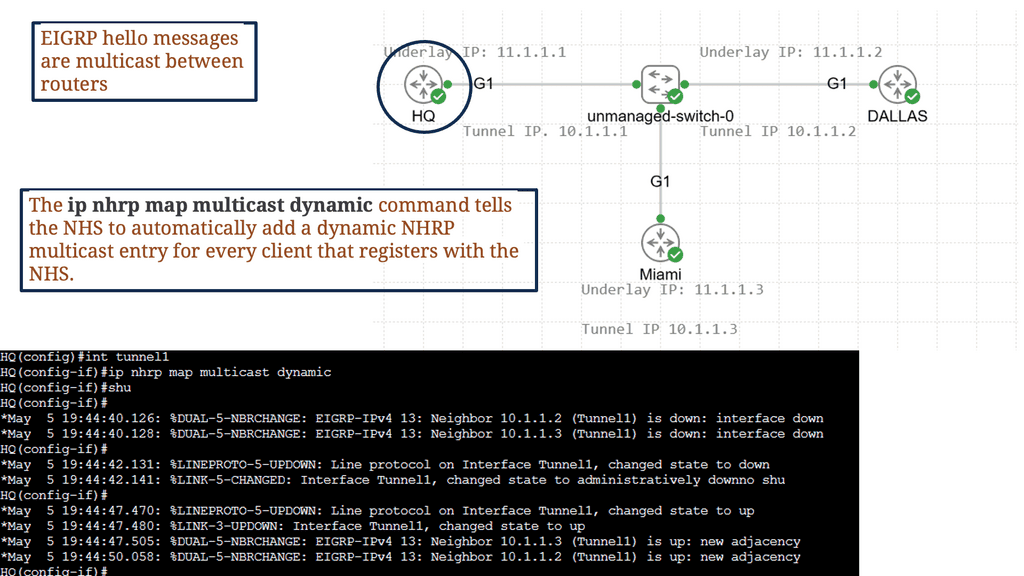
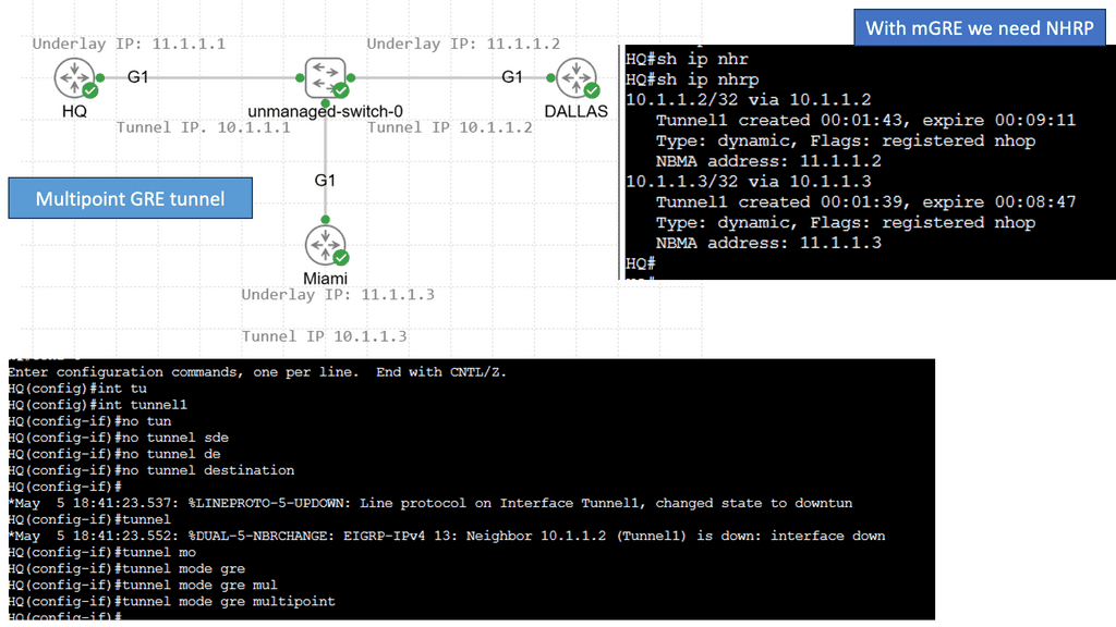
Multipoint GRE, or mGRE, is a tunneling protocol for encapsulating packets and transmitting them over an IP network. It enables virtual point-to-multipoint connections, allowing multiple endpoints to communicate simultaneously. By utilizing a single tunnel interface, mGRE simplifies network configurations and optimizes resource utilization.

One of Multipoint GRE’s standout features is its ability to transport multicast and broadcast traffic across multiple sites efficiently. It achieves this through a single tunnel interface, eliminating the need for dedicated point-to-point connections. This scalability and flexibility make mGRE an excellent choice for large-scale deployments and multicast applications.

Multipoint GRE & DMVPN:

DMVPN, as the name suggests, is a virtual private network technology that dynamically creates VPN connections between multiple sites without needing dedicated point-to-point links. It utilizes a hub-and-spoke architecture, with the hub as the central point for all communication. Using the Next Hop Resolution Protocol (NHRP), DMVPN provides a highly scalable and flexible solution for securely interconnecting sites.

Multipoint GRE, or mGRE, is a tunneling protocol my DMVPN uses to create point-to-multipoint connections. It allows multiple spokes to communicate directly with each other, bypassing the hub. By encapsulating packets within GRE headers, mGRE establishes virtual links between spokes, providing a flexible and efficient method of data transmission.

Data Analytics with GRE WAN

Data analytics becomes the intelligence layer that exposes how Point‑to‑Point Generic Routing Encapsulation (GRE) behaves when protected by IPsec across WAN and hybrid‑cloud environments. GRE‑over‑IPsec is widely used for scalable tunneling, multicast transport, and routing‑protocol carriage — but once encapsulated inside IPsec, its operational behavior becomes harder to observe. Analytics solves this by collecting telemetry at every stage: GRE header integrity, tunnel‑keepalive timing, IPsec SA lifetime, encryption‑overhead latency, packet‑loss patterns, MTU fragmentation events, and control‑plane protocol stability inside the GRE tunnel. This transforms GRE‑over‑IPsec from a “black‑box tunnel” into a measurable system.

Analytics reveals hidden issues such as asymmetric encryption paths, GRE keepalives failing due to IPsec rekeying, routing‑protocol jitter caused by ESP overhead, or fragmentation spikes when GRE+ESP headers exceed WAN MTU. By correlating GRE tunnel behavior with IPsec cryptographic performance, engineers gain precise visibility into how secure encapsulation affects routing stability and application flows.

When analytics is integrated directly with WAN controllers, IPsec key‑management engines, and routing stacks, GRE‑over‑IPsec becomes adaptive rather than fragile. Real‑time analytics feeds SD‑WAN orchestrators, IKEv2 negotiation engines, and tunnel‑health monitors with exact state: SA expiration trends, GRE keepalive loss, per‑hop encryption latency, and cross‑region tunnel symmetry.

With this intelligence, the system can rebalance tunnels across healthier paths, adjust MTU/MSS dynamically, tune rekey intervals, or pre‑emptively reroute flows before a GRE‑over‑IPsec tunnel degrades. In multi‑site or hybrid‑cloud designs, analytics validates consistency across tunnel endpoints, detects drift between IPsec policies, and predicts when GRE routing inside the encrypted tunnel is approaching instability thresholds. The result is a secure tunneling architecture that learns from telemetry, optimizes itself continuously, and maintains predictable performance even during rekey events, congestion, or heavy east‑west bursts. Data analytics transforms GRE‑over‑IPsec into a self‑optimizing, feedback‑driven secure transport fabric.

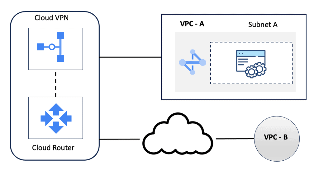
Google HA VPN

Understanding HA VPN

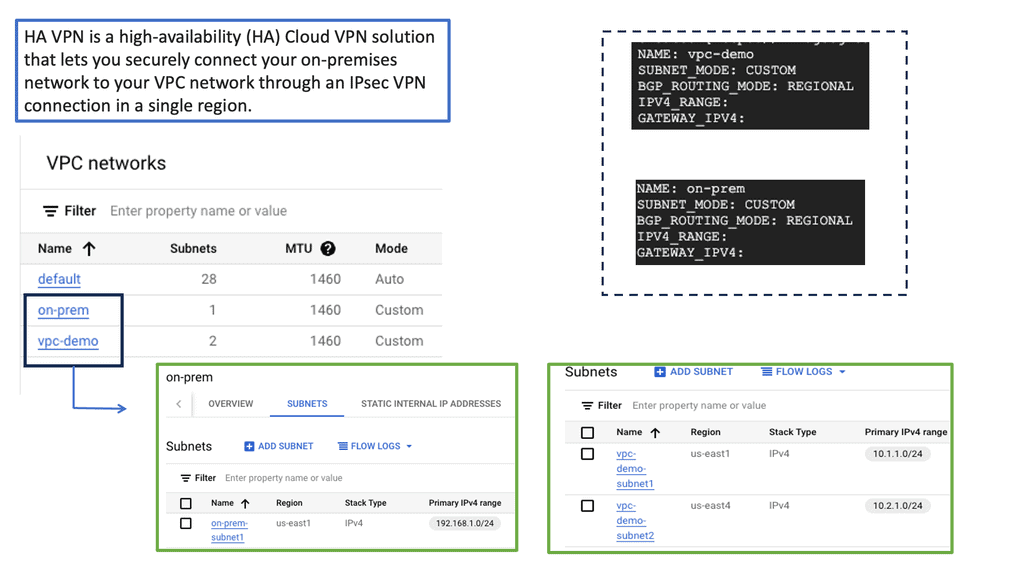
HA VPN is a highly scalable and redundant VPN solution provided by Google Cloud. It allows you to establish secure connections over the public internet while ensuring high availability and reliability. With HA VPN, you can connect your on-premises networks to Google Cloud, enabling secure data transfer and communication.

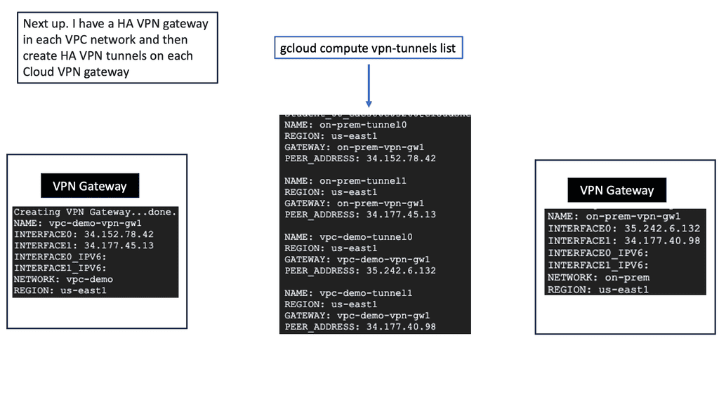
To begin configuring HA VPN, you must first set up a virtual private cloud (VPC) network in Google Cloud. This VPC network will serve as the backbone for your VPN connection. Next, you must create a VPN gateway and configure the necessary parameters, such as IP addresses, routing, and encryption settings. Google Cloud provides a user-friendly interface and comprehensive documentation to guide you through this process.

Once the HA VPN configuration is set up in Google Cloud, it’s time to establish connectivity with your on-premises networks. This involves configuring your on-premises VPN gateway or router to connect to the HA VPN gateway in Google Cloud. You must ensure that the IPsec VPN parameters, such as pre-shared keys and encryption algorithms, are correctly configured on both ends for a secure and reliable connection.

IPSec Security

Securing GRE:

IPsec, short for Internet Protocol Security, is a protocol suite that provides secure communication over IP networks. It operates at the network layer of the OSI model, offering confidentiality, integrity, and authentication services. By encrypting and authenticating IP packets, IPsec effectively protects sensitive data from unauthorized access and tampering.

Components of IPsec:

To fully comprehend IPsec, we must familiarize ourselves with its core components. These include the Authentication Header (AH), the Encapsulating Security Payload (ESP), Security Associations (SAs), and Key Management protocols. AH provides authentication and integrity, while ESP offers confidentiality and encryption. SAs establish the security parameters for secure communication, and Key Management protocols handle the exchange and management of cryptographic keys.

The adoption of IPsec brings forth a multitude of advantages for network security. First, it ensures data confidentiality by encrypting sensitive information, making it indecipherable to unauthorized individuals. Second, IPsec guarantees data integrity, as any modifications or tampering attempts would be detected. Additionally, IPsec provides authentication, verifying the identities of communicating parties, thus preventing impersonation or unauthorized access.

When IPsec and GRE are combined, they create a robust network security solution. IPsec ensures the confidentiality and integrity of data, while GRE enables the secure transmission of encapsulated non-IP traffic. This integration allows organizations to establish secure tunnels for transmitting sensitive information while extending their private networks securely.

Benefits of GRE over IPSEC:

Secure Data Transmission: By leveraging IPSEC’s encryption and authentication capabilities, GRE over IPSEC ensures the confidentiality and integrity of data transmitted over the network. This is particularly crucial when transmitting sensitive information, such as financial data or personal records.

Network Scalability: GRE over IPSEC allows organizations to create virtual private networks (VPNs) by establishing secure tunnels between remote sites. This enables seamless communication between geographically dispersed networks, enhancing collaboration and productivity.

Protocol Flexibility: GRE over IPSEC supports encapsulating various network protocols, including IPv4, IPv6, and multicast traffic. This flexibility enables the transmission of diverse data types, ensuring compatibility across different network environments.

The Role of VPNs

VPNs are deployed on an unprotected network or over the Internet to ensure data integrity, authentication, and encryption. Initially, VPNs were designed to reduce the cost of unnecessary leased lines. As a result, they now play a critical role in securing the internet and, in some cases, protecting personal information.

In addition to connecting to their corporate networks, individuals use VPNs to protect their privacy. Data integrity, authentication, and encryption through L2F, L2TP, GRE, or MPLS VPNs are impossible. However, IPsec can also benefit these protocols when combined with L2TP, GRE, and MPLS. These features make IPsec the preferred protocol for many organizations.

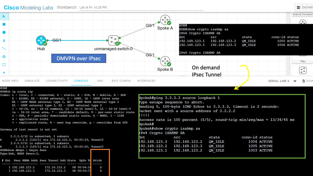
DMVPN over IPsec
Diagram: DMVPN over IPsec

GRE over IPsec

A GRE tunnel allows unicast, multicast, and broadcast traffic to be tunneled between routers and is often used to route traffic between different sites. A disadvantage of GRE tunneling is that it is clear text and offers no protection. Cisco IOS routers, however, allow us to encrypt the entire GRE tunnel, providing a safe and secure site-to-site tunnel.

RFC 2784 defines GRE (protocol 47), and RFC 2890 extends it. Using GRE, packets of any protocol (the payload packets) can be encapsulated over any other protocol (the delivery protocol) between two endpoints. Between the payload (data) and the delivery header, the GRE protocol adds its header (4 bytes plus options).

Tip:

GRE supports IPv4 and IPv6. If IPv4 or IPv6 endpoint addresses are defined, the outer IP header will be IPv4 or IPv6, respectively. In comparison to the original packet, GRE packets have the following overhead:

  • 4 bytes (+ GRE options) for the GRE header.
  • 20 bytes (+ IP options) for the outer IPv4 header (GRE over IPv4), or
  • 40 bytes (+ extension headers) for the outer IPv6 header (GRE over IPv6).

GRE over IPsec creates a new IP packet inside the network infrastructure device by encapsulating the original packets within GRE.

When GRE over IPsec is deployed in tunnel mode, the plaintext IPv4 or IPv6 packet is encapsulated into GRE. The tunnel source and destination IP addresses are then encapsulated in another IPv4 or IPv6 packet. An IPsec tunnel source and tunnel destination route the traffic to the destination with an additional outer IP header acting as a tunnel source and tunnel destination.

On the other hand, GRE over IPsec encapsulates plaintext IPv4 or IPv6 packets in GRE and then protects them with IPsec for confidentiality and integrity; the outer IP header with the source and destination addresses of the GRE tunnel enables packet routing.

IPsec site-to-site

An IPsec site-to-site VPN, also known as a gateway-to-gateway VPN, is a secure tunnel established between two or more remote networks over the internet. It enables organizations to connect geographically dispersed offices, data centers, or even cloud networks, creating a unified and secure network infrastructure. By leveraging IPsec, organizations can establish secure communication channels, ensuring confidentiality, integrity, and authentication of transmitted data.

GRE with IPsec

Advanced Topics

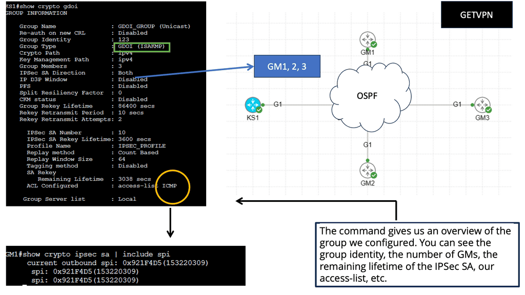
GETVPN:

– GetVPN, short for Group Encrypted Transport VPN, is a Cisco proprietary technology that provides secure site communication. It operates in the network layer and employs a key server to establish and distribute encryption keys to participating devices.

– This approach enables efficient and scalable deployment of secure VPNs across large networks. GetVPN offers robust security measures, including data confidentiality, integrity, and authentication, making it an excellent choice for organizations requiring high levels of security.

– When you run IPSec over a hub-and-spoke topology like DMVPN, the hub router has an IPSec SA with every spoke router. As a result, you are limited in the number of spoke routers you can use. Direct spoke-to-spoke traffic is supported in DMVPN, but when a spoke wants to send traffic to another spoke, it must first create an IPSec SA, which takes time.

Multicast traffic cannot be encapsulated with traditional IPSec unless first encapsulated with GRE.

GETVPN solves the scalability issue by using a single IPSec SA for all routers in a group. Multicast traffic is also supported without GRE.

Understanding IPv6 Tunneling

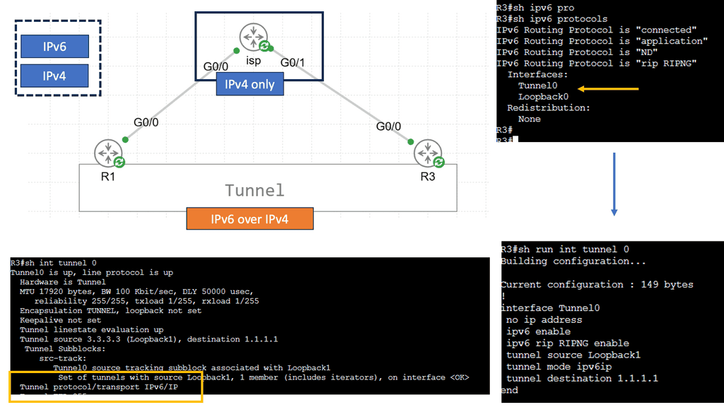
IPv6 tunneling is a mechanism that enables the encapsulation of IPv6 packets within IPv4 packets, allowing them to traverse an IPv4 network infrastructure. This allows for the coexistence and communication between IPv6-enabled devices over an IPv4 network. The encapsulated IPv6 packets are then decapsulated at the receiving end of the tunnel, restoring the original IPv6 packets.

Types of IPv6 Tunneling Techniques

There are several tunneling techniques used for IPv6 over IPv4 connectivity. Let’s explore a few prominent ones:

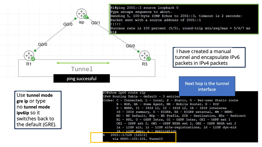
Manual IPv6 Tunneling: Manual IPv6 tunneling involves manually configuring tunnels on both ends. This method requires the knowledge of the source and destination IPv4 addresses and the tunneling protocol to be used. While it offers flexibility and control, manual configuration can be time-consuming and error-prone.

Automatic 6to4 Tunneling: Automatic 6to4 tunneling utilizes the 6to4 addressing scheme to assign IPv6 addresses to devices automatically. It allows IPv6 packets to be encapsulated within IPv4 packets, making them routable over an IPv4 network. This method simplifies the configuration process, but it relies on the availability of public IPv4 addresses.

Teredo Tunneling: Teredo tunneling is designed for IPv6 connectivity over IPv4 networks when the devices are located behind a NAT (Network Address Translation) device. It employs UDP encapsulation to transmit IPv6 packets over IPv4. Teredo tunneling can be helpful in scenarios where native IPv6 connectivity is unavailable.

Before you proceed, you may find the following posts helpful for pre-information:

  1. Dead Peer Detection
  2. IPsec Fault Tolerance
  3. Dynamic Workload Scaling 
  4. Cisco Switch Virtualization
  5. WAN Virtualization
  6. VPNOverview

Point-to-Point Generic Routing Encapsulation over IP Security

Guide on IPsec site to site

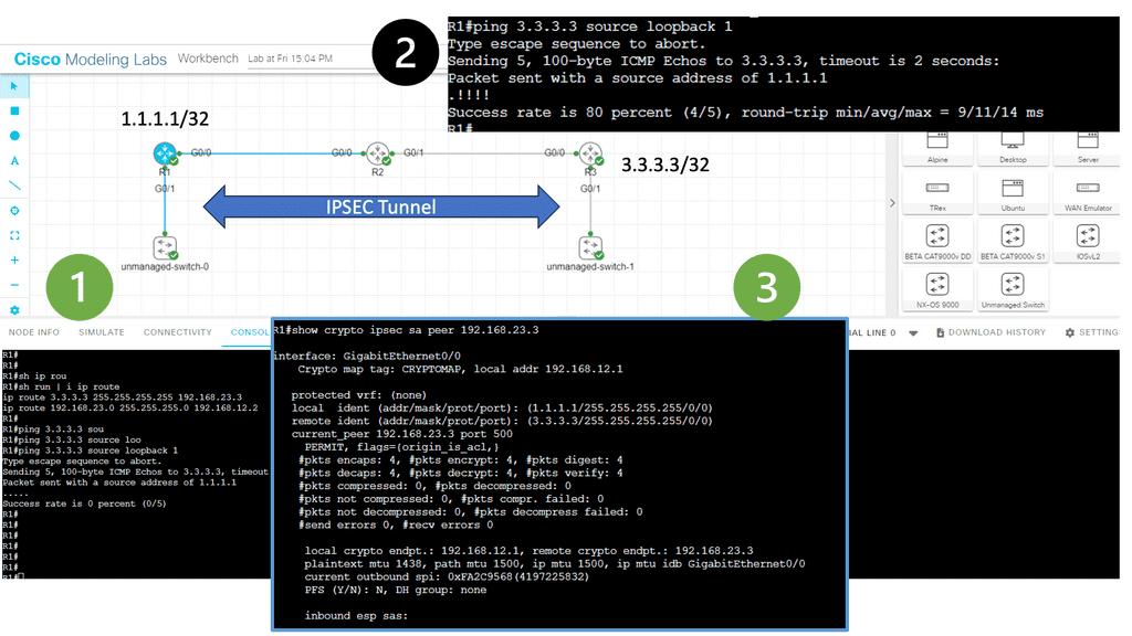
In this lesson, two Cisco IOS routers use IPSec in tunnel mode. This means the original IP packet will be encapsulated in a new IP packet and encrypted before sending it out of the network. For this demonstration, I will be using the following three routers.

R1 and R3 each have a loopback interface behind them with a subnet. We’ll configure the IPsec tunnel between these routers to encrypt traffic from 1.1.1.1/32 to 3.3.3.3/32. R2 is just a router in the middle, so R1 and R3 are not directly connected.

Notice with information 1 that we can’t ping the remote LAN. However, once the IPsec tunnel is up, we have reachability. Under the security associations, we have 4 packets encapsulated and encapsulated. However, I sent 5 pings. The first packet is lost to ARP.

ipsec tunnel
Diagram: IPsec Tunnel

IPsec relies on encryption and tunneling protocols to establish a secure connection between networks. The two primary components of IPsec are the IPsec tunnel mode and the IPsec transport mode. In tunnel mode, the entire IP packet is encapsulated within another IP packet, adding an extra layer of security. In contrast, the transport mode only encrypts the payload of the IP packet, leaving the original IP header intact.

To initiate a site-to-site VPN connection, the IPsec VPN gateway at each site performs a series of steps. These include negotiating the security parameters, authenticating the participating devices, and establishing a secure tunnel using encryption algorithms such as AES (Advanced Encryption Standard) or 3DES (Triple Data Encryption Standard). Once the tunnel is established, all data transmitted between the sites is encrypted, safeguarding it from unauthorized.

Back to basic with GRE tunnels

What is a GRE tunnel?

A GRE tunnel supplies connectivity to a wide variety of network layer protocols. GRE works by encapsulating and forwarding packets over an IP-based network. The authentic use of GRE tunnels provided a transport mechanism for non-routable legacy protocols such as DECnet and IPX. With GRE, we add header information to a packet when the router encapsulates it for transit on the GRE tunnel.

The new header information contains the remote endpoint IP address as the destination. The latest IP headers permit the packet to be routed between the two tunnel endpoints, and this is done without inspection of the packet’s payload.

After the packet reaches the remote endpoint, the GRE termination point, the GRE headers are removed, and the original packet is forwarded from the remote router. Both GRE and IPsec tunnels are used in solutions for SD WAN SASE and SD WAN Security. Both solutions abstract the complexity of configuring these technologies.

GRE Operation

GRE operates by encapsulating the original packet with a GRE header. This header contains information such as the source and destination IP addresses and additional fields for protocol identification and fragmentation support. Once the packet is encapsulated, it can be transmitted over an IP network, effectively hiding the underlying network details.

When a GRE packet reaches its destination, the receiving end decapsulates it, extracting the original payload. This process allows the recipient to receive the data as if it were sent directly over the underlying network protocol. GRE is a transparent transport mechanism, enabling seamless communication between disparate networks.

GRE Tunnel
Diagram: GRE tunnel example. Source is heficed

Guide on Point-to-Point GRE

Tunneling is putting packets into packets to transport them over a particular network. This is also known as encapsulation.

You might have two sites with IPv6 addresses on their LANs, but they only have IPv4 addresses when connected to the Internet. In normal circumstances, IPv6 packets would not be able to reach each other, but tunneling allows IPv6 packets to be routed on the Internet by converting IPv6 packets into IPv4 packets.

You might also want to run a routing protocol between your HQ and a branch site, such as RIP, OSPF, or EIGRP. By tunneling these protocols, we can exchange routing information between the HQ and branch routers.

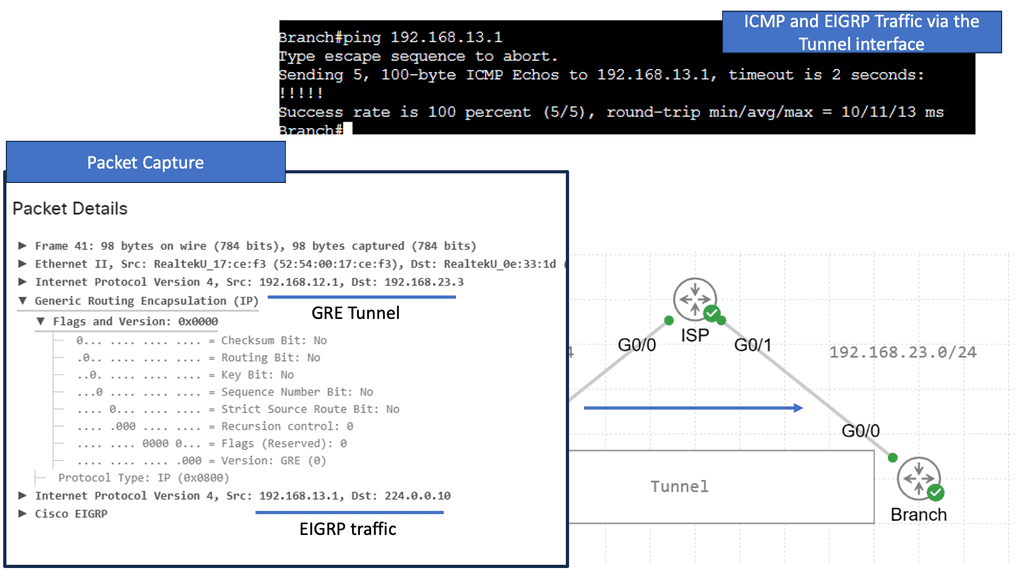
When you configure a tunnel, you’re creating a point-to-point connection between two devices. We can accomplish this with GRE (Generic Routing Encapsulation). Let me show you a topology to demonstrate the GRE.

GRE configuration

In the image above, we have three routers connected. We have our headquarters router on the left side. On the right side, there is a “Branch” router. There is an Internet connection on both routers. An ISP router is located in the middle, on top. This topology can be used to simulate two routers connected to the Internet. A loopback interface represents the LAN on both the HQ and Branch routers.

EIGRP will be enabled on the loopback and tunnel interfaces. Through the tunnel interface, both routers establish an EIGRP neighbor adjacency. The next hop is listed as the tunnel interface in the routing table. We use GRE to tunnel our traffic, but it does not encrypt it like a VPN does. Our tunnel can be encrypted using IPSEC, one of the protocols.GRE without IPsec

Guide on Point-to-Point GRE with IPsec

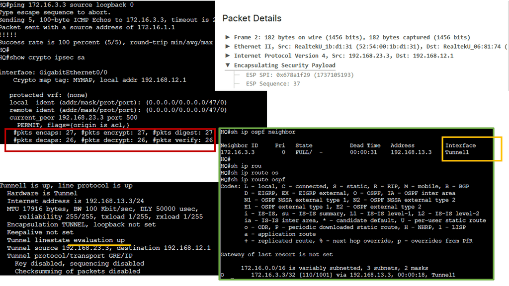
A GRE tunnel allows unicast, multicast, and broadcast traffic to be tunneled between routers and is often used to send routing protocols between sites. GRE tunneling has the disadvantage of being clear text and unprotected. Cisco IOS routers, however, support IPsec encryption of the entire GRE tunnel, allowing a secure site-to-site tunnel. The following shows an encrypted GRE tunnel with IPsec.

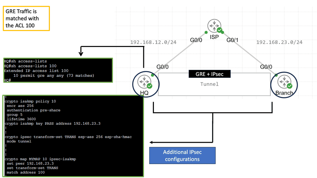
We have three routers above. Each HQ and Branch router has a loopback interface representing its LAN connection. The ISP router connects both routers to “the Internet.” I have created a GRE tunnel between the HQ and Branch routers; all traffic between 172.16.1.0 /24 and 172.16.3.0 /24 will be encrypted with IPsec.

GRE with IPsec

For the IPsec side of things, I have configured an ISAKMP policy. In the example, I specify that I want 256-bit AES encryption and that we want a pre-shared key. We rely on Diffie-Hellman Group 5 for key exchange. The ISAKMP security association’s lifetime is 3600 seconds. The pre-shared key needs to be on both routers highlighted with a circle. Also, I created a transform-set called ‘TRANS’ that specifies we want ESP AES 256-bit and HMAC-SHA authentication.

Then, we create a crypto map that tells the router what traffic to encrypt and what transform set to use.

ipsec plus GRE

**How GRE and IPSec Work Together**

GRE and IPSec often work together to enhance network security. GRE provides the encapsulation mechanism, allowing the creation of secure tunnels between networks. IPSec, on the other hand, provides the necessary security measures, such as encrypting and authenticating the encapsulated packets. By combining both technologies’ strengths, organizations can establish secure and private connections between networks, ensuring data confidentiality and integrity.

**Benefits of GRE and IPSec**

The utilization of GRE and IPSec offers several benefits for network security. Firstly, GRE enables the transport of multiple protocols over IP networks, allowing organizations to leverage different network layer protocols without compatibility issues. Secondly, IPSec provides a robust security framework, protecting sensitive data from unauthorized access and tampering. GRE and IPSec enhance network security, enabling organizations to establish secure connections between geographically dispersed networks.

Topologies and routing protocol support

– Numerous technologies connect remote branch sites to HQ or central hub. P2P Generic Routing Encapsulation ( GRE network ) over IPsec is an alternative design to classic WAN technologies like ATM, Frame Relay, and Leased lines. GRE over IPsec is a standard deployment model that connects several remote branch sites to one or more central sites. Design topologies include the hub-and-spoke, partial mesh, and full mesh.

– Both partial and full-mesh topologies experience limitations in routing protocol support. A full mesh design is limited by the overhead required to support a design with a full mesh of tunnels. Following a complete mesh requirement, a popular design option would be to deploy DMVPN. Regarding the context of direct connectivity from branch to hub only, hub-and-spoke is by far the most common design.

Guide with DMVPN and GRE

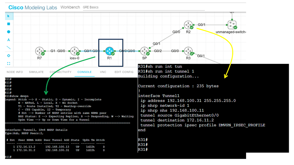
The lab guide below shows a DMVPN network based on Generic Routing Encapsulation (GRE), which is the overlay. Specifically, we use GRE in point-to-point mode, which means deploying DMVPN Phase 1, a true VPN hub-and-spoke design, where all traffic from the spokes must go via the hub. With the command show dmvpn, we can see that two spokes are dynamically registered over the GRE tunnel; notice the “D” attribute.

The beauty of using DMPVN as a VPN technology is that the hub site does not need a specific spoke configuration as it uses GRE in multi-point mode. On the other hand, the spokes need to have a hub configuration with the command: IP nhrp nhs 192.168.100.11. IPsec encryption is optional with DMVPN. In the other command snippet, we are running IPsec encryption with the command: tunnel protection ipsec profile DMVPN_IPSEC_PROFILE.

DMVPN configuration
Diagram: DMVPN Configuration.

One of GRE’s primary use cases is creating VPNs. By encapsulating traffic within GRE packets, organizations can securely transmit data across public networks such as the Internet. This provides a cost-effective solution for connecting geographically dispersed sites without requiring dedicated leased lines.

Another use of the GRE is network virtualization. By leveraging GRE tunnels, virtual networks can be created isolated from the underlying physical infrastructure. This allows for more efficient resource utilization and improved network scalability.

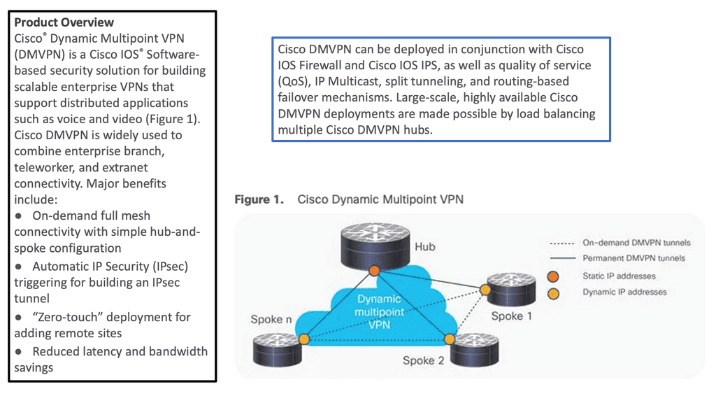
**DMVPN (Dynamic Multipoint VPN)**

DMVPN is based on the principle of dynamic spoke-to-spoke tunneling, which allows for dynamic routing and scalability. It also allows for the creation of a dynamic mesh topology, allowing multiple paths between remote sites. This allows for increased redundancy and improved performance.

DMVPN also offers the ability to establish a secure tunnel over an untrusted network, such as the Internet. This is achieved with a series of DMVPN phases. DMVPN phase 3 offers better flexibility by using IPSec encryption and authentication, ensuring that all traffic sent over the tunnel is secure. This makes DMVPN an excellent choice for businesses connecting multiple sites over an unsecured network.

Dynamic Multipoint VPN
Diagram: Example with DMVPN. Source is Cisco

GRE Network: Head-end Architecture 

Single-tier and dual-tier

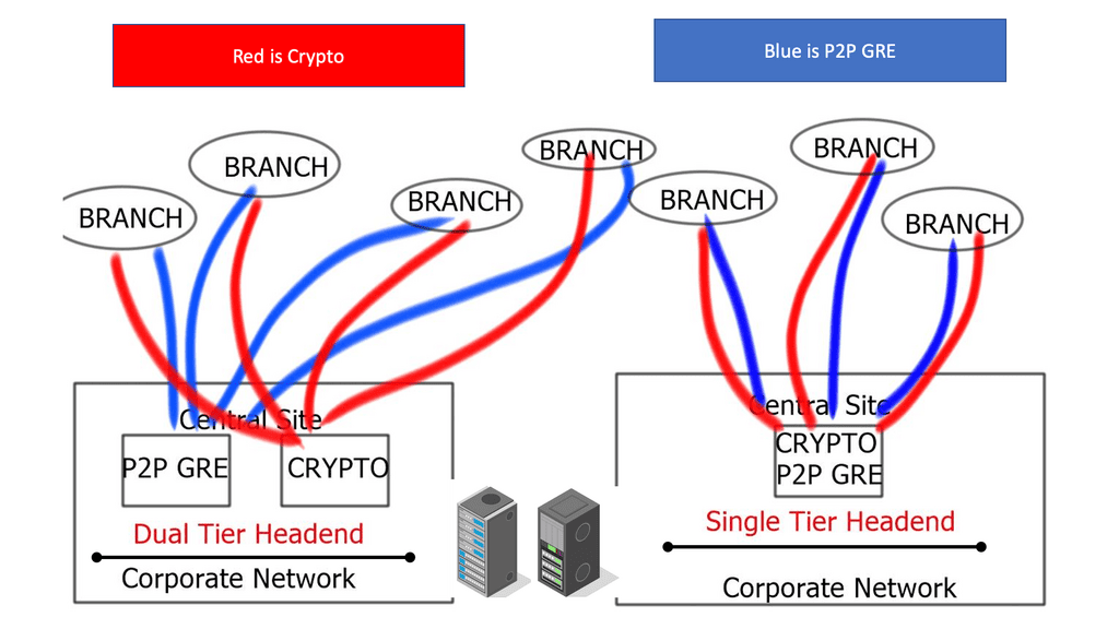
Head-end architectures include a single-tier head-end where the point-to-point GRE network and crypto functionality co-exist on the same device. Dual-tier designs are where the point-to-point GRE network and crypto functionality are not implemented on the same device. In dual-tier designs, the routing and GRE control planes are located on one device, while the IPsec control plane is housed on another.

what is generic routing encapsulation
Diagram: What is generic routing encapsulation?

Headend

Router

Crypto

Crypto IP

GRE  

GRE IP

Tunnel Protection

Single Tier

Headend

Static or Dynamic

Static

p2p GRE static

Static

Optional 


Branch

Static

Static or Dynamic

p2p GRE static

Static

Optional 

Dual Tier

Headend

Static or Dynamic

Static

p2p GRE static

Static

Not Valid


Branch

Static

Static or Dynamic

p2p GRE static

Static

Not Valid

“Tunnel protection” requires the same source and destination IP address for the GRE and crypto tunnels. Implementations of dual-tier separate these functions, resulting in the different IP addresses for the GRE and crypto tunnels. Tunnel protection is invalid with dual-tier mode.

GRE over IPsec

GRE (Generic Routing Encapsulation) is a tunneling protocol that encapsulates multiple protocols within IP packets, allowing the transmission of diverse network protocols over an IP network. On the other hand, IPSEC (IP Security) is a suite of protocols that provides secure communication over IP networks by encrypting and authenticating IP packets. Combining these two protocols, GRE over IPSEC offers a secure and flexible solution for transmitting network traffic over public networks.

Preliminary design considerations

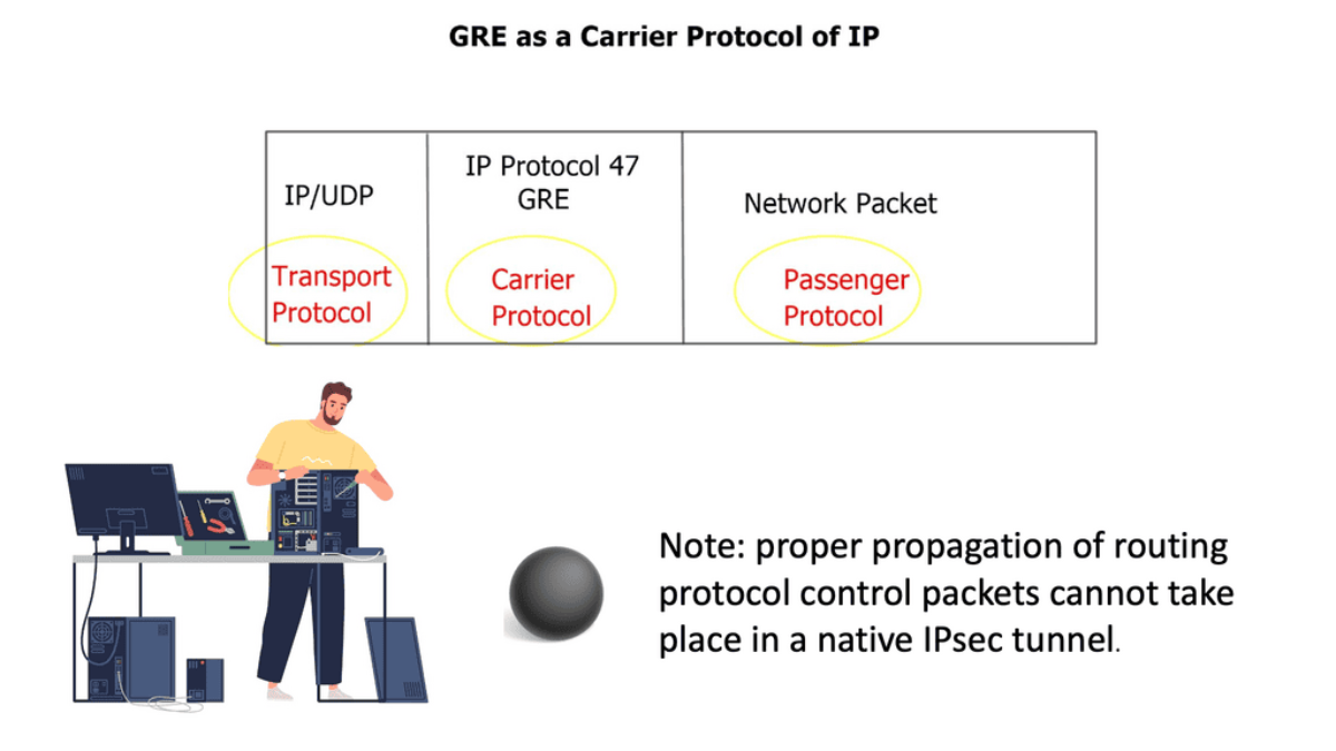
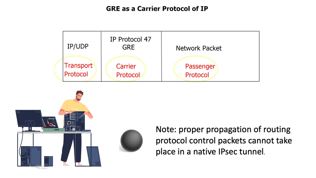
Diverse multi-protocol traffic requirements force the use of a Generic Routing Encapsulation ( GRE ) envelope within the IPsec tunnel. The p2p GRE tunnel is encrypted inside the IPsec crypto tunnel. Native IPsec is not multi-protocol and lacks IP multicast or broadcast traffic support. As a result, proper propagation of routing protocol control packets cannot occur in a native IPsec tunnel.

However, OSPF design cases allow you to run OSPF network type non-broadcast and explicitly configure the remote OSPF neighbors, resulting in OSPF over the IPsec tunnel without GRE. With a GRE over IPsec design, all traffic between hub and branch sites is first encapsulated in the p2p GRE packet before encryption.

GRE over IPsec
Diagram: GRE over IPSec.

**GRE over IPSec Key Points**

Redundancy:

Redundant designs are implemented with the branch having two or more tunnels to the campus head. The head-end routers can be geographically separated or co-located. Routing protocols are used with redundant tunnels, providing high availability with dynamic path selection.

The head-end router can propagate a summary route ( 10.0.0.0/8 ) or a default route ( 0.0.0.0/0 ) to the branch sites, and a preferred routing metric will be used for the primary path. If OSPF is RP, the head-end selection is based on OSPF costs.

Recursive Routing:

Each branch must add a static route to their respective ISP IP addresses for each head-end. The static avoids recursive routing through the p2p GRE tunnel. Recursive routing occurs when the route to the GRE tunnel source outside the IP address of the opposing router is learned via a route with a next-hop of the inside IP address of the opposing p2p GRE tunnel.

Recursive routing causes the tunnel to flap and the p2p GRE packets to route into their p2p GRE tunnel. To overcome recursive routing, my best practice is to ensure that the outside tunnel is routed directly to ISP instead of inside the p2p GRE tunnel.

%TUN-5-RECURDOWN: Tunnel0 temporarily disabled due to recursive routing

Recursive routing and outbound interface selection pose significant challenges in tunnel or overlay networks. Therefore, routing protocols should be used with utmost caution over network tunnels. A router can encounter problems if it attempts to reach the remote router’s encapsulating interface (transport IP address) via the tunnel. Typically, this issue occurs when the transport network is advertised using the same routing protocol as the overlay network.

Routers learn the destination IP address for tunnel interfaces through recursive routing. First, the IP address of the tunnel’s destination is removed from the routing table, making it unreachable.

Split tunneling

If the head-end advertises a summary route to the branch, split tunneling is enabled on all packets not destined for the summary. Any packets not destined for the summary are split-tunneled to the Internet. For example, split tunneling is not used for the branch sites in a design where the head-end router advertises a default route ( 0.0.0.0/0 ) through the p2p GRE tunnel.

A key point: Additional information on Split tunneling.

Split tunneling is a networking concept that allows users to selectively route traffic from their local device to a local or remote network. It gives users secure access to corporate networks and other resources from public or untrusted networks. Split tunneling can also be used to reduce network congestion. For example, if a user is on a public network and needs to access a resource on a remote network, the user can set up a split tunnel to send only the traffic that needs to go over the remote network. This reduces the traffic on the public network, allowing it to perform more efficiently.

Control plane

Routing protocol HELLO packets initiated from the branch office force the tunnel to establish—routing protocol control plane packets to maintain and keep the tunnel up. HELLO packets provide a function similar to GRE keepaways. The HELLO routing protocol operates in layer 3, and GRE is maintained in layer 2.

 Branch router considerations

The branch router can have p2p GRE over IPSEC with a static or dynamic public address. The GRE and crypto tunnels are sourced from a static address with a static public IP address. With dynamic address allocation, the GRE is sourced from a loopback address privately assigned (non-routable), and the crypto tunnel is sourced from a dynamically assigned public IP address.

Closing Points on GRE with IPsec

GRE allows for the encapsulation of packets from various network protocols, providing a versatile solution for creating point-to-point links. Meanwhile, IPsec ensures these connections are secure, encrypting the data to protect it from interception and tampering. In this blog post, we’ll explore how to implement a point-to-point GRE tunnel secured by IPsec on Google Cloud, helping you create a robust and secure network architecture.

The first step in establishing a secure point-to-point link is setting up GRE tunnels. GRE is a tunneling protocol that encapsulates a wide variety of network layer protocols inside virtual point-to-point links. When configuring GRE on Google Cloud, you’ll need to create a Virtual Private Cloud (VPC) network, assign static IP addresses to your virtual machines, and configure the GRE tunnels on both ends. This setup allows for seamless data transfer across your network, regardless of underlying network infrastructure.

Once the GRE tunnel is established, the next step is to secure it using IPsec. IPsec provides encryption and authentication services for your data, ensuring that only authorized users can access it and that the data remains unaltered during transmission. On Google Cloud, you can configure IPsec by setting up Cloud VPN or using third-party tools to establish a secure IPsec tunnel. This involves generating and exchanging security keys, configuring security policies, and ensuring that your firewall rules allow IPsec traffic. With IPsec, your GRE tunnel becomes a secure conduit for your data, protected from potential threats.

One of the key advantages of using Google Cloud for your GRE and IPsec setup is the seamless integration with other Google Cloud services. Whether you’re connecting different regions, linking on-premises networks with cloud resources, or setting up a hybrid cloud environment, Google Cloud’s suite of services can enhance your network’s functionality and performance. Services like Google Cloud Interconnect, Cloud DNS, and Cloud Load Balancing can be incorporated into your architecture to optimize data flow, manage traffic, and ensure high availability.

Summary: Point-to-Point Generic Routing Encapsulation over IP Security

Point-to-Point Generic Routing Encapsulation (P2P GRE) over IP Security (IPsec) stands out as a robust and versatile solution in the vast realm of networking protocols and security measures. This blog post will delve into the intricacies of P2P GRE over IPsec, exploring its features, benefits, and real-world applications.

Understanding P2P GRE

P2P GRE is a tunneling protocol that encapsulates various network layer protocols over IP networks. It establishes direct communication paths between multiple endpoints, creating virtual point-to-point connections. By encapsulating data packets within IP packets, P2P GRE enables secure transmission across public or untrusted networks.

Exploring IPsec

IPsec serves as the foundation for securing network communications. It provides authentication, confidentiality, and integrity to protect data transmitted over IP networks. By combining IPsec with P2P GRE, organizations can achieve enhanced security and privacy for their data transmissions.

Benefits of P2P GRE over IPsec

– Scalability: P2P GRE supports the creation of multiple tunnels, enabling flexible and scalable network architectures.

– Versatility: The protocol is platform-independent and compatible with various operating systems and network devices.

– Efficiency: P2P GRE efficiently handles encapsulation and decapsulation processes, minimizing overhead and ensuring optimal performance.

– Security: Integrating IPsec with P2P GRE ensures end-to-end encryption, authentication, and data integrity, safeguarding sensitive information.

Real-World Applications

P2P GRE over IPsec finds extensive use in several scenarios:

– Secure Site-to-Site Connectivity: Organizations can establish secure connections between geographically dispersed sites, ensuring private and encrypted communication channels.

– Virtual Private Networks (VPNs): P2P GRE over IPsec forms the backbone of secure VPNs, enabling remote workers to access corporate resources securely.

– Cloud Connectivity: P2P GRE over IPsec facilitates secure connections between on-premises networks and cloud environments, ensuring data confidentiality and integrity.

Conclusion:

P2P GRE over IPsec is a powerful combination that offers secure and efficient communication across networks. Its versatility, scalability, and robust security features make it an ideal choice for organizations seeking to protect their data and establish reliable connections. By harnessing the power of P2P GRE over IPsec, businesses can enhance their network infrastructure and achieve higher data security.