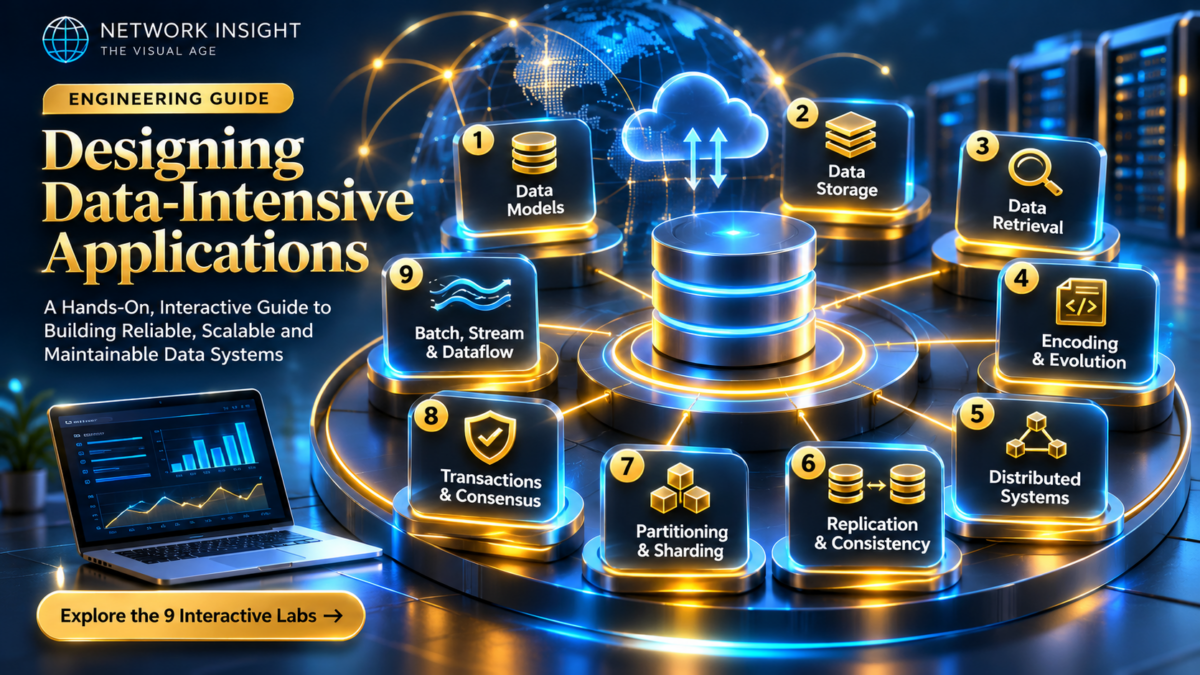
Designing Data-Intensive Applications: The Big Ideas Behind Reliable, Scalable, and Maintainable Systems
Modern applications are not simply programs connected to databases. They are distributed systems composed of storage engines, caches, message brokers, replicas, partitions, stream processors and services that must continue operating despite failures, unpredictable workloads and constantly evolving requirements.
The engineering challenge is to understand how data moves, where state lives, what happens when components fail, and which guarantees an architecture can actually provide.
Select a workload scenario to explore how requests travel between application services, caches, databases, replicas and asynchronous processing systems. Select any architecture component to inspect its engineering responsibilities and failure modes.
Application services coordinate business logic, access persistent storage, interact with caches and publish asynchronous events. Their reliability depends on timeouts, retries, idempotency, backpressure and well-defined failure boundaries.
Why Data-Intensive Applications Are Fundamentally Different
A traditional application may appear to perform a straightforward operation: receive a request, process some logic, store information and return a response. At small scale, the design may be relatively simple.
At production scale, the same operation can involve multiple independently failing systems. A request may pass through a gateway, query a cache, retrieve information from a replicated database, publish an event and trigger additional processing in another service.
Every boundary introduces engineering questions. What if the database acknowledges a write but the response is lost? What if a replica returns stale information? What if an event is delivered twice? What happens when a storage partition becomes overloaded?
These are not isolated implementation details. They are architectural properties that determine whether an application can remain dependable under real-world operating conditions.
The Central Engineering Principle
A reliable distributed application is not one in which failures never happen. It is one whose architecture explicitly anticipates failures, defines the guarantees users can rely on, and provides mechanisms to recover without violating critical correctness requirements.
Continue Operating Under Failure
Reliability means maintaining specified correctness and service guarantees despite hardware faults, software defects, network interruptions and operational mistakes. Redundancy, recovery, fault isolation and observability are central design concerns.
Handle Growing Workloads
Scalability is the ability to accommodate increasing load through deliberate architectural changes. Engineers must understand workload characteristics, latency distributions, throughput, data volume, hotspots and the limits of vertical or horizontal expansion.
Enable Safe System Evolution
Maintainability allows teams to diagnose, modify and extend systems without excessive complexity or operational risk. Clear interfaces, understandable data flows, automation, testing and compatibility strategies support long-term engineering success.
From Components to System Guarantees
The critical shift in distributed systems engineering is to stop evaluating components only in isolation. A database may offer durable writes, a message broker may offer replicated storage, and a cache may deliver sub-millisecond access, but these individual capabilities do not automatically create end-to-end reliability.
For example, writing a database record and subsequently publishing an event creates a potential consistency gap. The database transaction might commit while the event publication fails. Without an explicit mechanism such as a transactional outbox, the two operations may diverge.
Similarly, introducing replicas can improve availability and read capacity, but asynchronous replication may expose stale reads. Partitioning can distribute storage and workload, but a poor partition key can create hotspots. Retries may improve resilience to transient failures, but unsafe retries can duplicate side effects.
The objective of this guide is to connect these trade-offs into a coherent engineering model: data models, storage engines, replication, partitioning, transactions, distributed coordination and dataflow processing all contribute to the behavior of the complete application.
What You Will Engineer in This Guide
You will investigate database storage strategies, model replication lag, explore partitioning behavior, compare consistency guarantees, examine transaction anomalies and trace event-driven data pipelines. The interactive laboratories will turn architectural theory into observable system behavior, failure analysis and practical design decisions.
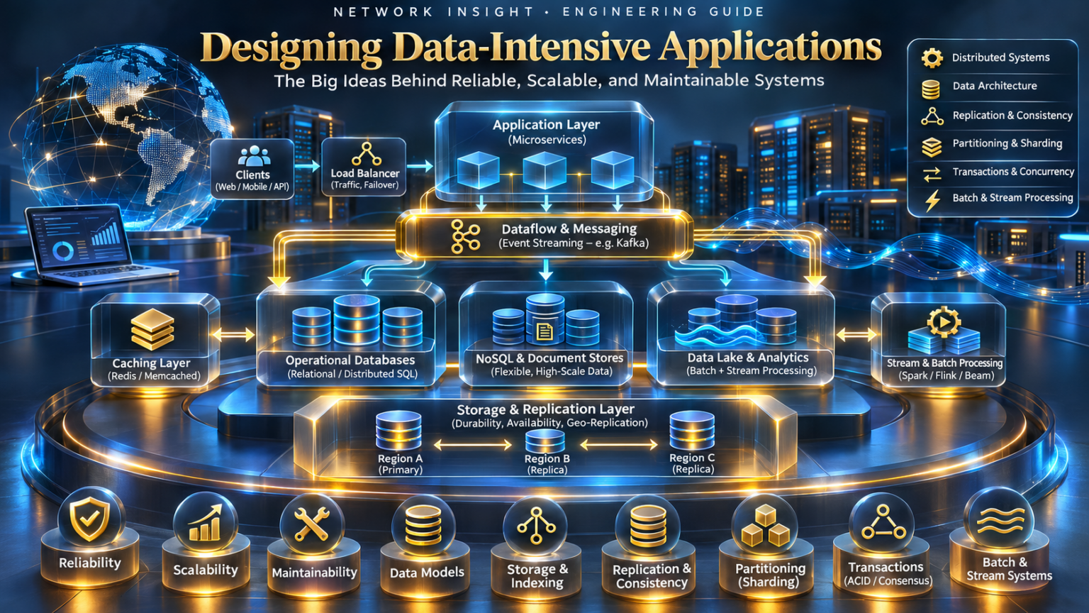
Explore the Architecture of Data-Intensive Systems
Nine connected engineering disciplines. One interactive journey through the systems that make modern applications reliable, scalable and maintainable.
Select a topic to inspect its engineering principles, then open the corresponding section and interactive laboratory.
Foundations of Data-Intensive Systems
Explore how clients, application services, databases, caches and event brokers combine to form a production data-intensive architecture.
Reliability, Scalability & Maintainability
The quality of a data-intensive application is determined not only by whether it works under normal conditions, but by how it behaves when hardware fails, workloads increase, software changes and operational complexity accumulates.
Three foundational engineering properties provide a framework for evaluating these systems: reliability, scalability and maintainability. Each property influences architectural decisions, operational processes and the guarantees experienced by users.
Correctness Despite Failure
Reliable systems continue satisfying defined requirements despite faults. A node failure should not necessarily become a service outage, but redundancy alone does not guarantee correctness. Recovery, failover, durable state, monitoring and fault isolation must work together.
Predictable Behavior Under Load
Scalability concerns how a system responds as workload characteristics change. Request rates, data volumes, read/write ratios, concurrency and hotspot distributions determine whether additional resources actually improve performance.
Safe Evolution Over Time
Maintainable systems are understandable, operable and adaptable. Clear interfaces, observability, automation, testing and controlled deployments reduce the cost and risk of changing complex software.
Adjust incoming workload and the number of application instances. Inject an instance failure or enable graceful degradation to observe how the modeled system responds. The simulator uses a simplified queueing and capacity model to illustrate engineering trade-offs; it does not measure real infrastructure.
System Operating Normally
The current workload is within the modeled processing capacity.
Engineering Experiment
Increase the request rate until the application approaches saturation. Then add instances and observe the modeled capacity increase. Inject a failure and compare the result with graceful degradation enabled. Consider why a real application might still be constrained by its database, shared locks, network or downstream dependencies.
Faults Are Inevitable. Outages Are Not Always Inevitable.
Distributed systems operate across multiple processes, machines and networks. Each component introduces potential failure modes: hardware defects, process crashes, network partitions, storage corruption, software defects and operational mistakes.
A fault is a deviation in one component. A failure occurs when the overall system stops providing its required service or violates a specified guarantee. A resilient architecture attempts to prevent individual faults from propagating into system-wide failures.
Techniques include replication, redundancy, health checks, automatic failover, bounded retries, circuit breakers, bulkheads, checkpointing and disaster recovery.
However, fault tolerance introduces additional complexity. A retry can duplicate a payment. An incorrectly configured failover can create competing leaders. An asynchronous replica can lose recently acknowledged writes if promoted without appropriate safeguards.
Engineers must therefore define the actual correctness requirements before selecting recovery mechanisms. Availability alone is not sufficient if the system returns incorrect information or silently loses critical data.
Reliability Design Question
If an application service writes a database record successfully but crashes before sending the HTTP response, should the client retry? The answer depends on whether the operation is idempotent and whether the system can safely recognize an already completed request.
Understanding Load Before Adding Infrastructure
A system cannot meaningfully be described as scalable without specifying the workload being scaled. Ten thousand lightweight cache reads may require very different resources from ten thousand database writes involving transactions, indexing and synchronous replication.
Useful load parameters include requests per second, concurrent users, read/write ratios, average payload size, database cardinality, query complexity, event ingestion rate and the distribution of requests across keys or partitions.
Performance must also be measured carefully. Average response time can hide severe user-visible degradation. Percentile latency, particularly P95 and P99, reveals how slower requests behave under contention, queueing and overload.
Horizontal scaling adds processing instances, while vertical scaling increases the resources available to an existing instance. Neither strategy automatically eliminates bottlenecks in shared databases, coordination mechanisms, locks, storage or network dependencies.
Why Tail Latency Matters
Consider a service that fans out to multiple downstream requests. Even if most dependencies respond quickly, the slowest required response may determine the end-to-end latency. As fan-out increases, the probability of encountering a slow dependency can rise.
Designing Systems That Engineers Can Understand and Change
Distributed applications evolve continuously. New features, schema changes, infrastructure migrations, security requirements and workload growth place sustained pressure on the architecture.
Maintainability is supported by three closely related properties: operability, simplicity and evolvability. Operability enables teams to run and diagnose the system. Simplicity reduces unnecessary complexity and makes system behavior easier to reason about. Evolvability allows the architecture to adapt safely as requirements change.
Clear ownership boundaries, explicit interfaces, versioned schemas, automated testing, structured logging, distributed tracing, infrastructure automation and documented recovery procedures help reduce operational risk.
Maintainability is therefore not merely a code-quality concern. It is a fundamental architectural property that influences deployment safety, incident response, recovery time and long-term engineering cost.
Network Insight Engineering Principle
A production architecture should be evaluated not only by its steady-state performance, but by how safely it fails, how predictably it scales and how effectively engineers can understand, operate and evolve it.
Inside a Data-Intensive Application
Modern applications are not simply a web server connected to a database. They combine distributed services, caching, durable storage, asynchronous messaging and replicated infrastructure. Explore how these components cooperate—and what happens when one fails.
Live Application Architecture
System healthyComponent Inspector
Application Service
Engineering Insight
Select a component or run a trace to investigate its role.
Request Trace
Logical execution sequenceEngineering Console
Local simulationSection 1 · The Fundamental Engineering Principle
A reliable data-intensive application must account for data correctness, response latency, throughput, partial failure and operational complexity. Each infrastructure component solves a particular problem, but also introduces new dependencies and failure modes.
Investigation: Compare the read and write paths. Then inject a primary database failure. Why might a cached read succeed while a new durable write fails?
Reliability, Scalability & Maintainability
The quality of a data-intensive application is determined not only by whether it works under normal conditions, but by how it behaves when hardware fails, workloads increase, software changes and operational complexity accumulates.
Three foundational engineering properties provide a framework for evaluating these systems: reliability, scalability and maintainability. Each property influences architectural decisions, operational processes and the guarantees experienced by users.
Correctness Despite Failure
Reliable systems continue satisfying defined requirements despite faults. A node failure should not necessarily become a service outage, but redundancy alone does not guarantee correctness. Recovery, failover, durable state, monitoring and fault isolation must work together.
Predictable Behavior Under Load
Scalability concerns how a system responds as workload characteristics change. Request rates, data volumes, read/write ratios, concurrency and hotspot distributions determine whether additional resources actually improve performance.
Safe Evolution Over Time
Maintainable systems are understandable, operable and adaptable. Clear interfaces, observability, automation, testing and controlled deployments reduce the cost and risk of changing complex software.
Adjust incoming workload and the number of application instances. Inject an instance failure or enable graceful degradation to observe how the modeled system responds. The simulator uses a simplified queueing and capacity model to illustrate engineering trade-offs; it does not measure real infrastructure.
System Operating Normally
The current workload is within the modeled processing capacity.
Engineering Experiment
Increase the request rate until the application approaches saturation. Then add instances and observe the modeled capacity increase. Inject a failure and compare the result with graceful degradation enabled. Consider why a real application might still be constrained by its database, shared locks, network or downstream dependencies.
Faults Are Inevitable. Outages Are Not Always Inevitable.
Distributed systems operate across multiple processes, machines and networks. Each component introduces potential failure modes: hardware defects, process crashes, network partitions, storage corruption, software defects and operational mistakes.
A fault is a deviation in one component. A failure occurs when the overall system stops providing its required service or violates a specified guarantee. A resilient architecture attempts to prevent individual faults from propagating into system-wide failures.
Techniques include replication, redundancy, health checks, automatic failover, bounded retries, circuit breakers, bulkheads, checkpointing and disaster recovery.
However, fault tolerance introduces additional complexity. A retry can duplicate a payment. An incorrectly configured failover can create competing leaders. An asynchronous replica can lose recently acknowledged writes if promoted without appropriate safeguards.
Engineers must therefore define the actual correctness requirements before selecting recovery mechanisms. Availability alone is not sufficient if the system returns incorrect information or silently loses critical data.
Reliability Design Question
If an application service writes a database record successfully but crashes before sending the HTTP response, should the client retry? The answer depends on whether the operation is idempotent and whether the system can safely recognize an already completed request.
Understanding Load Before Adding Infrastructure
A system cannot meaningfully be described as scalable without specifying the workload being scaled. Ten thousand lightweight cache reads may require very different resources from ten thousand database writes involving transactions, indexing and synchronous replication.
Useful load parameters include requests per second, concurrent users, read/write ratios, average payload size, database cardinality, query complexity, event ingestion rate and the distribution of requests across keys or partitions.
Performance must also be measured carefully. Average response time can hide severe user-visible degradation. Percentile latency, particularly P95 and P99, reveals how slower requests behave under contention, queueing and overload.
Horizontal scaling adds processing instances, while vertical scaling increases the resources available to an existing instance. Neither strategy automatically eliminates bottlenecks in shared databases, coordination mechanisms, locks, storage or network dependencies.
Why Tail Latency Matters
Consider a service that fans out to multiple downstream requests. Even if most dependencies respond quickly, the slowest required response may determine the end-to-end latency. As fan-out increases, the probability of encountering a slow dependency can rise.
Designing Systems That Engineers Can Understand and Change
Distributed applications evolve continuously. New features, schema changes, infrastructure migrations, security requirements and workload growth place sustained pressure on the architecture.
Maintainability is supported by three closely related properties: operability, simplicity and evolvability. Operability enables teams to run and diagnose the system. Simplicity reduces unnecessary complexity and makes system behavior easier to reason about. Evolvability allows the architecture to adapt safely as requirements change.
Clear ownership boundaries, explicit interfaces, versioned schemas, automated testing, structured logging, distributed tracing, infrastructure automation and documented recovery procedures help reduce operational risk.
Maintainability is therefore not merely a code-quality concern. It is a fundamental architectural property that influences deployment safety, incident response, recovery time and long-term engineering cost.
Network Insight Engineering Principle
A production architecture should be evaluated not only by its steady-state performance, but by how safely it fails, how predictably it scales and how effectively engineers can understand, operate and evolve it.
Reliability, Scalability & Maintainability
Operate a simulated production application. Increase request traffic, inject infrastructure failures and investigate how capacity, response latency and availability change. Restore service by applying engineering recovery actions.
Production Infrastructure
Incident Diagnosis
The application is operating within modeled capacity. Increase traffic or inject a failure to investigate the system.
Workload Generator
Engineering Event Console
Reliability Engineering Principles
Reliability
Maintain correct service behavior despite faults, overload and partial infrastructure failure.
Scalability
Understand how latency, throughput and resource requirements change as workload grows.
Maintainability
Design systems that engineers can understand, operate, repair and evolve safely.
Engineering Challenge
Increase traffic to 2,000 requests per second. Observe the application and database utilization. Add application instances, then inject a cache failure. Can scaling the application alone restore performance, or has the database become the limiting resource?
Data Models & Query Languages
A database is more than a place to store information. Its data model determines how application concepts are represented, how relationships are expressed, which queries are natural, and how the system can evolve as requirements change.
Relational, document and graph databases provide different abstractions for the same underlying information. Understanding their trade-offs is essential when designing reliable, scalable data-intensive applications.
Switch between relational, document and graph representations of the same sample application. Select a query to inspect its logical execution strategy and execute it against the built-in demonstration dataset.
Select a node to inspect how the model represents data and relationships.
Relational Data Model
Relational systems represent data as relations and use declarative queries to describe the required results.
Engineering Experiment
Execute the same query pattern using all three data models. Observe the logical operations involved and how relationships are represented. The reported counts describe this small demonstration dataset, not benchmarked database performance. Real execution costs depend on indexing, storage layout, caching, cardinality, query optimizers and workload.
Relational Models: Structured Data and Declarative Queries
The relational model organizes information into relations, commonly presented as tables. Each row represents a tuple and each column represents an attribute. Keys and constraints help preserve data integrity.
SQL provides a declarative interface: applications specify which results they require rather than manually describing every physical access step.
The database query optimizer can select indexes, join algorithms and access paths based on statistics, available resources and estimated execution costs.
Relational databases are especially useful when applications require complex queries, structured relationships, transactional consistency and strong integrity constraints.
Normalization reduces unnecessary duplication and helps prevent update anomalies, although carefully selected denormalization can improve specific read patterns.
The physical cost of joins depends on cardinality, indexing, data distribution and the selected execution plan. A join is not inherently slow, nor is a denormalized design inherently faster.
Document Models: Locality, Flexibility and Aggregates
Document databases represent information as self-contained records, commonly using JSON-like structures. Related information may be embedded within a single document, reducing the need for some cross-record lookups.
This model can be effective when application entities form natural aggregates, such as a customer profile with preferences and frequently accessed nested attributes.
However, embedding data introduces trade-offs. Frequently changing shared information may become duplicated across documents, and large embedded collections can create update or document-size challenges.
Document systems can support indexes, aggregation pipelines, transactions and cross-document queries, depending on the database implementation. The important architectural decision is how document boundaries align with application access patterns and consistency requirements.
Graph Models: Relationships as First-Class Data
Graph databases represent information using vertices and edges. Vertices describe entities, while edges explicitly represent relationships between them. Both may carry properties.
Graph models are particularly expressive when applications need to explore variable relationship paths, such as social networks, dependency maps, fraud detection systems, recommendation relationships and network topology analysis.
Rather than repeatedly reconstructing relationships through joins or application logic, a graph query can express traversal patterns directly.
Graph databases are not automatically faster for every workload. Traversal efficiency depends on the graph structure, indexing, partitioning, query planner and the selectivity of the starting nodes.
Choosing the Right Data Model
| Engineering Concern | Relational | Document | Graph |
|---|---|---|---|
| Primary Abstraction | Relations and tuples | Documents and aggregates | Vertices and edges |
| Relationship Representation | Keys and joins | Embedding and references | Explicit edges |
| Common Strength | Complex queries and integrity | Aggregate-oriented access | Relationship traversal |
| Potential Challenge | Complex joins and schema evolution | Duplication and document boundaries | Partitioning highly connected graphs |
| Typical Applications | Financial and transactional systems | Profiles and content systems | Topology and dependency analysis |
Network Insight Engineering Principle
Choose a data model according to the relationships your application must represent, the queries it must execute, the consistency guarantees it requires and the changes it must support. Database selection should follow workload analysis rather than technology popularity.
Data Models & Query Languages
Explore how the same application data can be represented using relational tables, JSON documents and graph relationships. Execute equivalent queries and inspect the logical operations required to retrieve connected information.
Relational Data Model
Interactive data representationQuery Workbench
Execution Trace
Engineering Interpretation
Choose a database model to investigate its strengths and trade-offs.
Engineering Challenge
Execute all three queries using each data model. Compare how relational databases use keys and joins, document databases use embedded or referenced data, and graph databases traverse explicit relationships. Which representation is most natural for your application's dominant access patterns?
Storage Engines & Indexing Architecture
Every database must translate logical operations into physical storage activity. Behind a simple read or write request are data structures, memory buffers, indexes, disk pages, transaction logs and background maintenance operations.
Two influential storage-engine families are B-tree-based engines and log-structured merge-tree (LSM-tree) engines. Their design choices affect read amplification, write amplification, space amplification, latency and operational behavior under sustained workloads.
Select a storage engine and execute write, read, flush and compaction operations. Observe the logical storage path and inspect how records move between memory and persistent structures. This is a deterministic teaching model, not a database benchmark.
LSM-Tree Write Path
A write is appended to a write-ahead log and inserted into an in-memory memtable. When the memtable reaches its threshold, it can be flushed to an immutable SSTable.
Engineering Experiment
Write several records into the LSM-tree. Observe automatic memtable flushes, create multiple SSTables and run compaction. Then switch to the B-tree model and perform the same logical operations. Compare the different storage paths and consider the effects on read, write and space amplification.
How Databases Turn Logical Records into Physical Storage
A storage engine is responsible for managing the physical representation of data and providing efficient mechanisms for reading, writing and recovering records.
A simple key-value interface may expose operations such as PUT, GET and DELETE, but the implementation must decide how records are organized on disk, how indexes are maintained and how updates survive process or machine failures.
Storage engines often use memory buffers, persistent logs, sorted data structures, page caches and background maintenance processes to balance performance and durability.
The main engineering trade-offs are often described through three forms of amplification.
Read amplification measures how much physical work is required to satisfy a logical read.
Write amplification measures how much physical data is written relative to the logical data being updated.
Space amplification describes additional storage consumed by indexes, obsolete versions, fragmentation and maintenance structures.
B-Trees: Page-Oriented Indexed Storage
B-trees organize sorted keys into a balanced hierarchy of pages. Internal pages contain separator keys and references to child pages, while leaf pages contain indexed entries or references to records.
A lookup traverses the tree from the root toward the appropriate leaf. Because each page can contain many keys, B-trees have high fan-out and relatively shallow depth.
Updates modify the relevant logical pages. Depending on the storage engine, these changes may first be recorded in a write-ahead log and applied through a buffer pool before modified pages are persisted.
B-trees are widely used in transactional databases because they support indexed lookups, range scans and ordered access patterns efficiently.
Engineering Consideration
B-tree performance depends on page size, cache effectiveness, tree height, insertion patterns, page splits, storage characteristics and concurrency control. Random updates may create additional storage I/O, although buffering and logging can substantially change the physical write pattern.
LSM-Trees: Sequential Writes and Background Compaction
Log-structured merge-trees organize updates around in-memory write buffers and immutable sorted files. Incoming writes are typically appended to a write-ahead log and inserted into a memtable.
When the memtable reaches a configured threshold, its contents are written to an immutable sorted-string table, or SSTable. Over time, multiple SSTables accumulate and must be merged or reorganized through compaction.
Compaction removes obsolete versions, can reclaim space associated with deleted records and reduces the number of overlapping files that must be consulted during reads.
This architecture can be effective for sustained write-heavy workloads, but compaction consumes CPU, memory bandwidth and storage I/O. Poorly tuned compaction can increase tail latency and create unpredictable resource contention.
Engineering Consideration
LSM-tree performance depends on memtable sizing, SSTable organization, compaction strategy, Bloom filters, block caches, key distributions and available I/O bandwidth. Write efficiency must be evaluated alongside read amplification and background maintenance costs.
Choosing Between B-Tree and LSM-Tree Designs
| Engineering Property | B-Tree | LSM-Tree |
|---|---|---|
| Primary Structure | Balanced page hierarchy | Memtables and immutable sorted files |
| Write Pattern | Logical page updates | Buffered writes and sequential flushes |
| Read Path | Tree traversal | Memtable and SSTable lookup |
| Background Maintenance | Page management and structural changes | Flushes and compaction |
| Potential Bottleneck | Random I/O and page contention | Compaction I/O and read amplification |
| Common Strength | Indexed reads and range access | Buffered write-heavy workloads |
Network Insight Engineering Principle
Storage-engine design is a trade-off between read efficiency, write efficiency, storage overhead, durability and operational predictability. Evaluate the complete workload and physical storage behavior rather than assuming that one indexing architecture is universally superior.
B-Tree vs LSM-Tree Storage Engines
Investigate two fundamental database storage architectures. Insert keys, execute lookups, observe B-tree node splitting and explore how log-structured merge trees use memory buffers, immutable files and background compaction.
B-Tree Page Structure
Engine readyStorage Operation Workbench
Enter an integer key from 1 to 999, then select an operation.
Execution Trace
Engineering Interpretation
B-trees maintain ordered keys in pages. LSM-trees buffer writes and merge sorted files in the background.
Engineering Challenge
Insert several keys into both engines. Observe how a B-tree reorganizes its pages, while an LSM-tree accumulates records in a memtable and flushes them into immutable SSTables. Then run compaction and consider the trade-off between write throughput, read amplification and background I/O.
Encoding, Serialization & Data Evolution
Data-intensive applications evolve continuously. Services are upgraded, database schemas change, events are retained for years, and different software versions may operate simultaneously during rolling deployments.
The central engineering challenge is ensuring that data written by one software version can still be interpreted correctly by another. This requires careful serialization design, schema evolution rules and compatibility testing.
Select an encoding format, producer schema and consumer schema. Execute the compatibility test to observe how different application versions interpret the same logical record. The laboratory models common schema-evolution rules rather than implementing full binary serialization libraries.
Schema Evolution Laboratory
Compatibility depends on the encoding format, field identifiers, default values and the rules used by producers and consumers.
Engineering Experiment
Begin with a Version 1 producer and Version 2 consumer. Then reverse the versions. Finally, select Version 3 to explore a deliberately incompatible field-type change. Repeat the experiment across JSON, Protocol Buffers and Avro-style representations.
Why Applications Need Encoding and Decoding
Applications operate on in-memory objects, structures and values. To transmit data over a network or persist it in storage, those values must be represented as a sequence of bytes.
Encoding, also called serialization, converts application data into a transferable representation. Decoding, or deserialization, reconstructs information from that representation.
Different formats make different trade-offs involving readability, payload size, schema enforcement, type information and compatibility.
Text-oriented formats such as JSON are easy to inspect and widely supported, but may require additional conventions for precise numeric types, binary values and schema validation.
Binary formats such as Protocol Buffers and Avro can provide compact representations and explicit schema evolution mechanisms.
The best format depends on application requirements, interoperability, operational tooling and the expected lifetime of encoded records.
Backward and Forward Compatibility
Backward compatibility means that newer software can read data written by older software. This is particularly important when services are upgraded while historical records remain stored in databases or event logs.
Forward compatibility means that older software can read data written by newer software. This matters during rolling deployments when updated producers may communicate with consumers that have not yet been upgraded.
Compatibility depends on the exact encoding and schema rules. Adding an optional field is often compatible, but changing a field's type, reusing a Protocol Buffers field number or removing a required Avro field without a suitable default can break decoding.
Engineering Design Principle
Treat schema evolution as an explicit compatibility contract. Validate producer and consumer combinations before deployment, especially when data is retained longer than the lifetime of an individual application release.
Why Multiple Software Versions Must Coexist
Large distributed applications rarely upgrade every component simultaneously. Rolling deployments replace instances incrementally to preserve service availability and reduce deployment risk.
During an upgrade, an application may contain old producers, new producers, old consumers and new consumers at the same time.
Schema changes must therefore be designed around a period of mixed versions. A common approach is to introduce compatible fields first, deploy consumers that understand the new representation, update producers and only later remove obsolete fields when safe.
This is often described as an expand-and-contract migration. It reduces the need for coordinated deployment across all services.
JSON vs Protocol Buffers vs Avro
| Property | JSON | Protocol Buffers | Avro |
|---|---|---|---|
| Representation | Text | Binary | Binary or JSON encoding |
| Schema | Optional external validation | Explicit message schema | Explicit writer/reader schemas |
| Field Identification | Field names | Numeric field tags | Schema-based field resolution |
| Evolution Mechanism | Application-defined rules | Stable field numbers and compatible types | Writer/reader schema resolution |
| Common Use | REST APIs and configuration | RPC and service communication | Event pipelines and data storage |
Network Insight Engineering Principle
A data format is not merely a serialization choice. It is a long-lived interface between software versions, services and stored information. Design schemas for compatibility, validate evolution rules and ensure that deployments can tolerate mixed-version operation.
Encoding & Schema Evolution
Explore how producers and consumers exchange encoded data while applications evolve independently. Introduce schema changes, test reader/writer compatibility and simulate the deployment risks of changing data contracts.
Producer → Consumer Architecture
Schema version transition: V1 → V2Schema V1
Schema V2
Select a schema change and run the compatibility test.
Compatibility Matrix
| Direction | Result |
|---|---|
| New reader ← Old writer | — |
| Old reader ← New writer | — |
| Both directions | — |
Deployment Sequence
Engineering Interpretation
Compatibility depends on the encoding format, reader behavior, field identity and the application's assumptions—not simply whether a field exists.
Engineering Challenge
First add a field with a default. Then introduce a required field without a default and test a rolling deployment. Investigate why new consumers may fail when reading older records and why field renaming can behave differently in name-based and tag-based encodings.
Replication & Consistency Engineering
Replication allows distributed databases to maintain multiple copies of information across independent machines or locations. It can improve availability, increase read capacity and support disaster recovery.
However, replication introduces fundamental engineering challenges: when does a write become visible, how do replicas remain synchronized, and what happens when a leader fails before its latest changes have propagated?
Write records to the leader, control replication delay and compare reads from the leader and followers. Inject a leader failure and promote a replica to investigate availability and the risk of losing unreplicated writes.
Leader / Follower Replication
Writes are accepted by the leader and propagated asynchronously to followers. Reads from lagging followers may return earlier versions of the data.
Engineering Experiment
Set replication delay to five seconds. Write a new value, then immediately read from Follower 1. Compare that result with a leader read. Next, fail the leader before the followers catch up and promote the most advanced replica. Investigate which acknowledged writes may have been lost.
Why Distributed Databases Maintain Multiple Copies
Replication maintains copies of data across multiple database nodes. It can reduce dependence on a single machine and improve resilience against hardware failures.
Replicas may also serve read traffic, reducing load on the primary node. Geographically distributed replicas can improve locality for some application workloads.
However, each additional copy must be kept synchronized. Network delays, process failures and concurrent updates create consistency challenges.
In leader-based replication, one node accepts writes and propagates changes to follower replicas.
Asynchronous replication allows the leader to acknowledge writes before followers have applied them. This can reduce write latency, but creates a window in which replicas contain older state.
Synchronous replication waits for selected replicas to acknowledge required stages of replication, potentially improving durability guarantees at the cost of additional latency or availability.
Understanding Stale Reads and Read-After-Write Guarantees
Replication lag occurs when a follower has not yet applied all changes accepted by the leader. A read directed to that follower may return an older value.
This behavior is commonly associated with eventual consistency. If writes stop and replication continues successfully, replicas are expected to converge toward the same state.
Applications may require stronger guarantees. Read-after-write consistency ensures that a client can observe its own completed writes. Monotonic reads prevent a client from observing progressively older versions as requests move between replicas.
Such guarantees can be implemented through leader reads, session affinity, version tracking, replica catch-up checks or stronger coordination, depending on the system architecture.
Engineering Consideration
A user updates a profile and immediately refreshes the page. If the subsequent read is served by a lagging replica, the old profile may reappear. Read-after-write consistency mechanisms can prevent this confusing behavior.
Failover, Promotion and the Risk of Data Loss
When a leader becomes unavailable, a replication system may promote a follower to accept new writes. The promotion process must determine which replica is sufficiently current and ensure that the old leader cannot continue accepting conflicting writes.
Asynchronous replication creates a potential data-loss window. If the leader acknowledged a write before any follower received it, promoting a lagging replica may discard that acknowledged update.
Production systems use combinations of replication positions, quorum protocols, leader epochs, fencing tokens and coordination services to manage these risks.
Failover is therefore not simply a matter of selecting another machine. It is a distributed correctness problem involving state, ordering and leadership.
Common Replication Architectures
| Architecture | Primary Characteristic | Engineering Trade-Off |
|---|---|---|
| Single-Leader | One node coordinates writes | Simple write ordering; failover required |
| Multi-Leader | Multiple nodes accept writes | Conflict detection and resolution |
| Leaderless | Clients coordinate with replicas | Quorum choices and reconciliation |
| Synchronous | Selected acknowledgements required | Stronger durability options; added latency |
| Asynchronous | Replication follows accepted writes | Lower acknowledgement latency; lag risk |
Network Insight Engineering Principle
Replication improves resilience only when its consistency guarantees, acknowledgement rules and failover behavior are explicitly understood. More replicas do not automatically eliminate stale reads, conflicting leadership or data-loss risk.
Replication, Consistency & Failover Engineering
Operate a simulated leader/follower database cluster. Commit writes, inspect replica lag, compare acknowledgement policies and investigate what happens when a leader fails before its followers receive the latest data.
Three-Node Replication Cluster
Cluster healthyConceptual replication architecture. The log index represents applied records, not a physical database WAL implementation.
Consistency Investigation
All replicas currently contain the same data. Introduce replication lag and compare read results.
Replication Controls
Replication Timeline
Distributed Systems Event Console
Replication / acknowledgement / failoverEngineering Challenge
Set replication delay to 10 seconds and select asynchronous acknowledgement. Commit two writes, immediately read from follower C, then fail the leader before replication completes. Elect a new leader and inspect the acknowledged writes that were not preserved. Reset and repeat using synchronous acknowledgement.
Partitioning & Distributed Data Engineering
When a dataset becomes too large for one machine, distributed databases divide information into partitions or shards and assign those partitions to different storage nodes.
The engineering challenge is not simply distributing records. It is ensuring that data placement remains predictable, workloads stay balanced and the cluster can expand or recover without excessive data movement.
Choose a partitioning strategy, generate a workload, add storage nodes and simulate failures. Observe how records are mapped to shards, how load becomes uneven and how many keys move during rebalancing.
Cluster Initialized
Four storage nodes are available. Generate a workload to observe key distribution and load.
Awaiting Workload
The simulator will identify uneven traffic, partition movement and the effects of node failure.
Engineering Experiment
Generate a uniform workload using modulo hashing. Add a node and rebalance. Then reset and repeat with consistent hashing. Compare how many stored keys change owners. Finally, select a hot-key workload to investigate why adding capacity does not necessarily remove a single-key hotspot.
Why Databases Partition Data
Partitioning divides a logical dataset into smaller subsets that can be placed on separate machines. Each partition typically owns a particular subset of keys or key ranges.
This allows storage capacity and processing demand to be distributed across multiple nodes. Queries can be routed to the partition that owns the required records.
Partitioning is distinct from replication. Partitioning distributes different records, while replication maintains multiple copies of the same records.
Production distributed databases often combine both techniques, using partitioning for scale and replication for fault tolerance.
Hash, Range and Consistent Hashing Strategies
Hash partitioning applies a hash function to a key and uses the result to select a partition. This can distribute well-chosen keys evenly, but a simple modulo-based scheme may remap many keys when node counts change.
Range partitioning assigns contiguous key ranges to partitions. It supports efficient range queries but can concentrate traffic if frequently accessed or sequentially increasing keys fall into the same range.
Consistent hashing places nodes and keys onto a logical hash ring. When membership changes, ownership can shift for only part of the keyspace rather than requiring a complete modulo remapping.
Engineering Consideration
Real systems commonly use virtual nodes, fixed logical partitions or token ranges to improve balance and control data movement. The simulator demonstrates the core placement principles using a simplified single-copy model.
Why Evenly Distributed Data Can Still Produce Uneven Traffic
A database may distribute stored keys evenly while still experiencing severe workload imbalance. A popular customer, product or account identifier can attract a disproportionate share of requests.
If all operations for that identifier must reach the same partition, its storage node can become overloaded while other nodes remain underutilized.
Mitigation techniques include caching, request coalescing, careful partition-key design, selective replication, workload isolation and, where semantics permit, splitting a logical hot key across multiple physical keys.
Moving Partitions Without Destabilizing the Cluster
Rebalancing changes the ownership of records or partitions when nodes are added, removed or overloaded. The objective is to improve capacity utilization without disrupting application availability.
Data migration consumes network bandwidth, disk I/O and CPU resources. Large migrations can compete with foreground queries and increase application latency.
Production systems may throttle migration, move partitions incrementally, track ownership epochs and coordinate cutover so that reads and writes are routed correctly throughout the transition.
Network Insight Engineering Principle
Effective partitioning distributes both data and workload while keeping ownership changes predictable. Evaluate key distribution, traffic skew, rebalancing cost and recovery behavior together rather than optimizing only the number of records per node.
Choosing a Data Placement Strategy
| Strategy | Strength | Primary Risk |
|---|---|---|
| Modulo Hashing | Simple deterministic placement | Broad remapping when node count changes |
| Range Partitioning | Efficient ordered and range access | Sequential-key and workload hotspots |
| Consistent Hashing | Reduced ownership movement | Ring imbalance without sufficient tokens |
| Fixed Logical Shards | Logical ownership separated from physical nodes | Shard metadata and migration complexity |
Database Sharding, Hot Partitions & Rebalancing
Operate a distributed database partitioning layer. Select a routing strategy, increase workload, inject a hot key and investigate how partition placement influences throughput, utilization and fault tolerance.
Distributed Shard Architecture
Four active shardsEngineering Diagnosis
Workload is distributed evenly across the four shards. Introduce skew or failure to investigate bottlenecks.
Partitioning Controls
Architecture Interpretation
Hash partitioning distributes keys using a deterministic hash function. It generally balances uniformly distributed keys, but a single hot key still maps to one partition.
Partitioning Event Console
Routing / capacity / failure analysisEngineering Challenge
Increase workload to 4,000 RPS, inject a hot key accounting for 60% of traffic, and observe shard saturation. Try rebalancing. Why does moving ordinary partitions fail to eliminate a hotspot caused by a single indivisible key? Consider key salting, workload splitting and replication-aware read distribution.
Transactions, Isolation & Distributed Consensus
Distributed applications must preserve correctness even when multiple clients modify shared data, transactions overlap and infrastructure failures interrupt communication.
The central challenge is determining which operations may execute concurrently, which updates can safely commit and how distributed nodes agree on a consistent sequence of decisions.
Switch between two engineering environments. First, investigate concurrent transactions modifying a shared account balance. Then explore how a three-node replicated cluster handles quorum acknowledgements, leader failure and network isolation.
Transaction Laboratory Ready
Run a concurrent transaction scenario to investigate lost updates and isolation behavior.
Engineering Experiment
Execute two concurrent balance increments using unsafe read-modify-write, then repeat using optimistic version validation and serializable execution. Switch to the consensus laboratory, isolate the leader, compare acknowledgement policies and investigate why a majority is required before committing a replicated decision.
Why Databases Need Transactions
Transactions group database operations into logical units of work. They allow applications to reason about changes without exposing arbitrary intermediate states to other clients.
The ACID properties describe important transaction guarantees: atomicity, consistency, isolation and durability. These properties address different aspects of correctness.
Atomicity ensures that a transaction's changes are applied as a unit. Isolation controls interference between concurrent transactions. Durability concerns the persistence of committed changes.
Database consistency refers to preserving application-defined invariants, which must still be expressed through constraints, transaction logic and correct data models.
Lost Updates, Write Skew and Isolation Levels
A lost update occurs when two transactions read the same value, independently calculate a replacement and write their results without detecting the conflict.
For example, two clients read a balance of 100 and each add 10. If both write 110, one increment is lost. Correct execution should produce 120.
Other anomalies include dirty reads, non-repeatable reads, phantom reads and write skew. The guarantees associated with named isolation levels can differ between database implementations.
Serializable isolation aims to make concurrent transactions behave as though they executed in some valid sequential order, even when the database internally uses concurrency.
Engineering Consideration
Snapshot isolation can prevent many anomalies but does not automatically eliminate write skew. Applications with cross-record invariants may need serializable transactions, explicit constraints or additional coordination.
Consensus, Quorums and Replicated Logs
Distributed consensus allows a group of nodes to agree on decisions despite certain failures and communication delays. Consensus protocols are central to replicated state machines, metadata services and strongly coordinated distributed databases.
Majority-based consensus systems typically require more than half the voting members to participate in decisions. With three voting nodes, a majority consists of two nodes.
A leader may propose log entries and replicate them to followers. Under protocol-specific safety rules, an entry can become committed after the required acknowledgements.
Leader terms, log matching and election restrictions help prevent conflicting leaders from committing incompatible histories. These mechanisms are more sophisticated than merely counting acknowledgements.
Availability, Consistency and Failure Boundaries
A network partition prevents some distributed nodes from communicating with others. Systems must decide whether to continue accepting operations when coordination becomes impossible.
A majority-based replicated state machine normally prevents an isolated minority from committing new decisions. This protects agreement but can make some requests unavailable.
The CAP theorem concerns the trade-off between availability and linearizable consistency during network partitions, under its specific formal definitions. It does not mean every database must permanently choose only two of three desirable properties.
Network Insight Engineering Principle
Transaction correctness and distributed agreement are separate but related engineering problems. Isolation protects application invariants during concurrent execution, while consensus coordinates shared decisions across potentially failing nodes.
Concurrency and Coordination Mechanisms
| Mechanism | Purpose | Important Limitation |
|---|---|---|
| Read Committed | Avoid reading uncommitted changes | Does not prevent every lost update or write skew |
| Snapshot Isolation | Consistent transaction snapshot | Write skew may remain possible |
| Serializable Isolation | Equivalent to a valid serial order | Coordination, retries or contention costs |
| Optimistic Validation | Detect conflicting writes before commit | Applications must handle aborts and retries |
| Majority Consensus | Coordinate replicated decisions | Minority partitions cannot make progress |
Transactions, Isolation & Distributed Consensus
Investigate concurrent database operations, transaction anomalies and the coordination required to safely commit data across multiple nodes.
Concurrent Transaction Timeline
Interactive execution modelEngineering Diagnosis
Select a concurrency scenario and isolation level, then execute the transactions.
Execution Trace
Engineering Interpretation
Isolation determines which interleavings are permitted and which conflicts must be prevented or resolved.
Engineering Event Console
Engineering Challenge
Run the write-skew scenario under snapshot isolation and then under serializable isolation. Observe why protecting individual rows from concurrent updates does not necessarily preserve a cross-row invariant. Next, switch to the consensus environment and investigate how losing a majority affects write availability.
Batch Processing, Stream Processing & Dataflow Systems
Modern data-intensive applications continuously generate events from services, users, databases and infrastructure. These events must be collected, transported, transformed and delivered to downstream systems.
The engineering challenge is designing reliable data pipelines that preserve ordering where required, control processing lag, recover from failures and support replay without corrupting downstream state.
Adjust producer throughput, consumer capacity and the number of active consumers. Generate events, inspect partition lag, inject a consumer failure and replay events from the last committed checkpoint.
Pipeline Initialized
Generate events to observe throughput, processing lag and consumer capacity.
Checkpoint State
No events have been processed. Checkpoint offsets are currently zero.
Engineering Experiment
Set producer throughput to 200 events per tick and consumer capacity to 20. Run several ticks and observe backlog growth. Increase the consumer group size and investigate how partition count limits parallelism. Commit a checkpoint, process more events, inject a consumer failure and replay from the checkpoint to explore at-least-once processing behavior.
How Event-Driven Systems Move Information
Event-driven architectures represent changes as records that can be published to durable logs or messaging systems. Producers generate events while downstream consumers process them.
A partitioned log provides an ordered sequence within each partition. Consumers track their progress using offsets that identify positions in those sequences.
Partitioning allows event processing to scale horizontally. Multiple consumers in one consumer group can process different partitions concurrently.
Ordering is generally guaranteed within a partition rather than across the entire distributed topic. Partition-key selection therefore affects both ordering and throughput.
Two Complementary Models for Data Computation
Batch processing operates on bounded datasets. Jobs read a defined collection of records, perform transformations and produce outputs.
Stream processing operates on potentially unbounded sequences of events. It can continuously update aggregates, detect patterns and respond to incoming changes.
Modern dataflow systems often combine these models. A streaming pipeline may process historical events through replay while also handling new events as they arrive.
The distinction is therefore not necessarily the underlying data, but how computations define input boundaries, progress and completion.
What Happens When Producers Outrun Consumers
Backpressure emerges when incoming work exceeds the rate at which downstream components can process it.
In durable event-log architectures, unprocessed records accumulate as consumer lag. This provides temporary buffering but does not eliminate capacity limits.
Sustained lag increases processing delay and may eventually exceed retention or resource budgets.
Engineers respond by scaling consumers, increasing processing efficiency, adjusting partition counts, reducing unnecessary work or applying upstream rate control.
Engineering Consideration
Adding consumers beyond the number of partitions does not increase partition-level parallelism within one consumer group. Capacity planning must account for partition ownership, processing cost and traffic skew.
Recovering Dataflow State After Failure
Stream processors track progress using offsets, checkpoints or durable state snapshots.
After a failure, a consumer can resume from a committed checkpoint. If some records were processed after that checkpoint, those records may be processed again.
This is a common basis for at-least-once delivery semantics. Downstream systems must therefore consider duplicate processing.
Exactly-once effects require stronger coordination, such as transactional sinks, idempotent writes, deduplication or atomic checkpoint-and-output mechanisms, depending on the system.
Building Reliable Production Dataflows
| Engineering Concern | Typical Mechanism | Failure Risk |
|---|---|---|
| Ordering | Partition keys and ordered logs | Unexpected cross-partition reordering |
| Throughput | Partitioning and consumer scaling | Processing lag and hot partitions |
| Recovery | Offsets and durable checkpoints | Replay and duplicate processing |
| Correctness | Idempotency and transactional outputs | Duplicate or missing side effects |
| Observability | Lag, throughput and failure metrics | Undetected pipeline degradation |
Network Insight Engineering Principle
A reliable data pipeline must coordinate event ordering, processing capacity, durable progress and downstream correctness. High throughput alone does not guarantee reliable or consistent results.
Connecting the Principles of Data-Intensive Applications
Reliable distributed systems are built from a collection of interacting architectural decisions: storage engines, data models, replication strategies, partitioning algorithms, transaction guarantees and dataflow mechanisms.
Every decision creates trade-offs involving latency, throughput, operational complexity, availability and correctness.
The central engineering skill is understanding how these mechanisms behave under real workloads and infrastructure failures, rather than evaluating components in isolation.
Batch, Stream & Dataflow Systems
Operate a partitioned event-streaming architecture. Generate events, control producer and consumer throughput, investigate backpressure, checkpoint offsets and simulate consumer recovery through event replay.
Event Streaming Architecture
Pipeline idlePartition Offsets
Engineering Diagnosis
The pipeline is idle. Start event generation to observe producer and consumer behavior.
Pipeline Engineering Controls
Processing Semantics
Stream mode processes available records incrementally. Checkpoints store consumer positions. Replaying from an older checkpoint may reprocess records whose effects were already applied.
Batch vs Stream Processing
Architectural comparisonContinuously consumes newly available events.
Supports low-latency transformations and event-driven applications.
Requires offset management, recovery and backpressure handling.
Processes bounded collections of records.
Useful for historical analysis, bulk transformations and recomputation.
Scheduling and batch size influence processing delay.
Dataflow Engineering Event Console
Offsets / lag / checkpoint / recoveryEngineering Challenge
Start the stream with producer throughput above consumer capacity. Observe growing lag. Commit a checkpoint, process additional events, then replay from the checkpoint and inspect the number of repeated processing attempts. Finally, fail a consumer and investigate how the remaining consumer capacity affects the partition backlog.

- Designing Data-Intensive Applications: Reliable, Scalable, and Maintainable Systems - November 22, 2026
- AI Model Serving Performance Engineering Explained - November 20, 2026
- NVIDIA InfiniBand Networking Architecture Explained - November 20, 2026