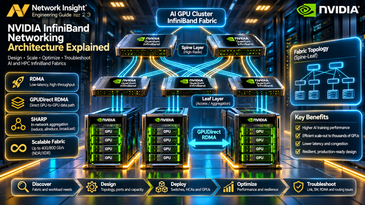
NVIDIA InfiniBand Networking Architecture Explained
How NVIDIA Quantum InfiniBand fabrics connect thousands of GPUs using high-bandwidth switching, RDMA, GPUDirect RDMA, adaptive routing and collective communication acceleration.
Modern AI training clusters rely on coordinated communication between many GPU servers. During distributed training, accelerators exchange gradients, model parameters and other intermediate data. The network must carry these transfers with predictable performance while supporting large numbers of concurrent flows.
InfiniBand is a high-performance networking architecture designed around low-latency transport, hardware-assisted communication, lossless link-level flow control and fabric-wide management. NVIDIA's Quantum switch families and ConnectX/SuperNIC adapters provide the infrastructure used in supported large-scale AI and HPC deployments.
Inside a High-Performance InfiniBand GPU Cluster
A scale-out GPU cluster connects server host channel adapters (HCAs) to an InfiniBand switching fabric. Separate rails can provide additional aggregate bandwidth and distinct failure domains, depending on how the topology is engineered.
The Technologies Behind an InfiniBand Fabric
NVIDIA Quantum Switches
High-bandwidth InfiniBand switches interconnect HCAs and provide the physical switching topology for scale-out workloads.
Host Channel Adapters
HCAs connect hosts to the InfiniBand fabric and implement hardware-assisted transport and RDMA operations.
Remote Direct Memory Access
RDMA enables supported memory transfers with hardware offload and reduced CPU involvement in the data path.
GPUDirect RDMA
Supported GPU, PCIe and network adapter configurations allow network devices to access registered GPU memory without mandatory host-memory staging.
Subnet Manager
The Subnet Manager discovers the fabric, assigns local identifiers and programs forwarding information for InfiniBand operation.
NVIDIA SHARP
Supported switch and software configurations can accelerate selected collective communication operations through in-network processing.
Follow the InfiniBand Communication System
Select a component to explore its role in GPU cluster networking and the corresponding logical data path.
GPU servers connect through HCAs to a switched InfiniBand fabric. Leaf-spine and multi-rail designs can provide scalable bandwidth and multiple communication paths when engineered with appropriate topology and routing.
Understanding the Architectural Differences
InfiniBand and Ethernet-based RoCEv2 can both support RDMA, but they use different link, addressing, transport and management models. RoCEv2 carries RDMA traffic over an Ethernet/IP network; native InfiniBand uses InfiniBand fabric addressing and transport.
| Characteristic | InfiniBand | Ethernet with RoCEv2 |
|---|---|---|
| Network architecture | InfiniBand link, switching and transport architecture. | Ethernet switching with IP/UDP-encapsulated RDMA traffic. |
| Fabric control | Subnet Manager and InfiniBand fabric configuration. | Ethernet/IP control plane and network management. |
| Flow control | InfiniBand credit-based link flow control. | Ethernet mechanisms such as PFC/ECN where designed and supported. |
| RDMA capability | Native InfiniBand transport and RDMA operations. | RDMA over Converged Ethernet v2. |
| Operational emphasis | Fabric discovery, LIDs, ports, links, routes and congestion. | IP routing, QoS, ECN/PFC, congestion and loss management. |
Engineering distinction: NVLink and NVSwitch typically address high-bandwidth GPU connectivity within supported server or rack-scale domains, while InfiniBand commonly provides scale-out connectivity between servers. They complement one another rather than representing interchangeable network technologies.
What You Will Be Able to Investigate
Across the nine sections, we will progress from physical InfiniBand topology and Quantum switching through RDMA queue pairs, GPU memory transfers, fabric management, adaptive routing, congestion control, SHARP acceleration and production GPU cluster troubleshooting.
The focus is practical: understanding why a fabric forwards traffic, where bottlenecks arise, how RDMA communication is established, and how engineers isolate failures across adapters, switches, routing, software and GPU workloads.
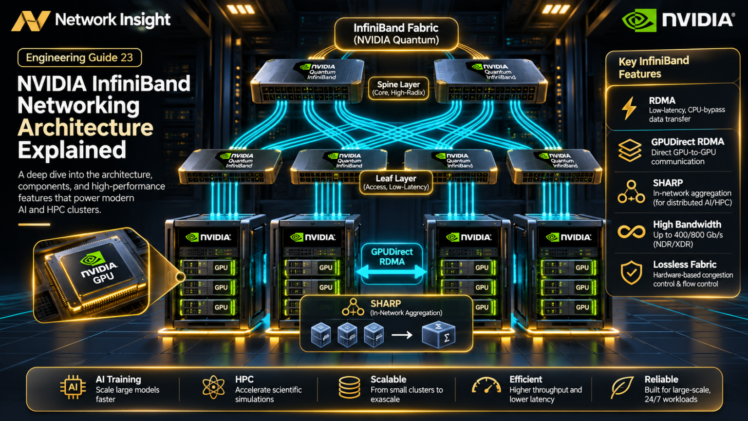
Explore the InfiniBand Architecture
Navigate nine advanced engineering sections covering NVIDIA Quantum switching, RDMA transport, GPUDirect, subnet management, adaptive routing, SHARP, GPU cluster design and production troubleshooting.
GPU nodes connect through HCAs to leaf switches, which provide fabric connectivity through the Quantum spine tier.
Progress reflects sections reached while browsing this page. It does not represent a knowledge assessment.
Follow the engineering journey from fabric architecture to production-scale AI cluster troubleshooting.
InfiniBand Architecture Fundamentals
InfiniBand is a switched, high-performance interconnect architecture that connects compute nodes, accelerators and storage systems using dedicated transport semantics, hardware-assisted communication and fabric-wide management.
In AI GPU clusters, InfiniBand provides scale-out connectivity between servers. Applications and communication libraries use the host networking stack and RDMA-capable adapters to exchange data across the fabric.
Understanding the physical topology, InfiniBand addressing model, HCA resources and fabric management functions is the foundation for engineering reliable GPU cluster networks.
How GPU Servers Connect Through an InfiniBand Network
A typical InfiniBand fabric consists of server HCAs, high-speed links and interconnected switches. Leaf-spine designs provide multiple paths between hosts, while multi-rail deployments can increase aggregate bandwidth and separate traffic across distinct fabrics.
Core InfiniBand Hardware and Logical Components
Host Channel Adapter
The HCA implements InfiniBand transport capabilities and exposes hardware resources used by RDMA applications.
InfiniBand Switch
Switches forward InfiniBand packets according to configured forwarding state and supported routing mechanisms.
Ports and Links
Physical ports connect adapters and switches using supported cable, optical and link-speed configurations.
Subnet Manager
Discovers the subnet, assigns LIDs and programs forwarding information required for fabric operation.
Queue Pair
Send and receive work queues support communication operations through the HCA.
Completion Queue
Reports completion information for supported RDMA work requests.
GUIDs, LIDs and InfiniBand Addressing
InfiniBand uses several identifiers for different purposes. A Globally Unique Identifier (GUID) identifies fabric entities, while a Local Identifier (LID) supports forwarding within an InfiniBand subnet.
The Subnet Manager assigns and manages LIDs as part of subnet initialization. InfiniBand also supports Global Identifiers (GIDs), which are important in broader addressing and transport contexts.
| Identifier | Purpose | Engineering Relevance |
|---|---|---|
| Node GUID | Identifies an InfiniBand node. | Inventory, discovery and fabric management. |
| Port GUID | Identifies an InfiniBand port. | Port identity and diagnostic correlation. |
| LID | Local identifier assigned within a subnet. | Subnet-local packet forwarding and route investigation. |
| GID | 128-bit global identifier. | Addressing and supported transport contexts. |
| QP Number | Identifies a queue pair in its relevant transport context. | RDMA connection and work-request troubleshooting. |
Engineering distinction: An InfiniBand LID is not an IP address. IP over InfiniBand (IPoIB) can carry IP traffic over an InfiniBand fabric, but native RDMA applications do not require conventional TCP/IP forwarding for their InfiniBand transport operations.
How RDMA Work Requests Become Fabric Traffic
RDMA applications typically register memory and create the required communication resources before posting work requests to a queue pair.
The HCA processes supported work requests and generates InfiniBand transport traffic. Remote adapters process the received operations according to the selected transport service and resource state.
Reliable Connection (RC), Unreliable Connection (UC) and Unreliable Datagram (UD) are examples of InfiniBand transport services. Their semantics and supported operations differ.
Why the Subnet Manager Is Essential
The Subnet Manager is a central component of InfiniBand subnet operation. It discovers the topology, assigns LIDs, establishes routing state and manages selected fabric attributes.
Production deployments may use redundant management instances, but only the active master Subnet Manager performs the authoritative subnet-management role at a given time.
| Management Function | Purpose | Failure Impact |
|---|---|---|
| Fabric discovery | Identify connected devices and links. | Topology changes may not be incorporated correctly. |
| LID assignment | Provide subnet-local forwarding identifiers. | New or reinitialized ports may not become operational. |
| Route programming | Configure switch forwarding state. | Connectivity or path availability can be affected. |
| Partition configuration | Manage supported partition membership. | Communication permissions may differ from the intended design. |
| Management failover | Maintain subnet-management continuity. | Loss of active management can impair recovery and topology changes. |
Follow Six InfiniBand Architecture Functions
Select an architecture function to inspect its role and the corresponding logical processing path.
A GPU server hosts accelerators, CPUs, memory and networking adapters. Communication libraries coordinate distributed operations and use supported RDMA interfaces to transfer data between hosts.
Inspecting InfiniBand Devices and Links
Linux systems with the appropriate InfiniBand software stack and hardware can expose adapter, port and fabric information through standard utilities.
Operational caution: InfiniBand tools depend on installed RDMA software packages, supported HCAs, driver versions and fabric permissions. Avoid modifying Subnet Manager configuration or switch forwarding state during an incident without an approved change procedure.
Engineering a Reliable InfiniBand Fabric
Bandwidth and Oversubscription
Evaluate HCA bandwidth, leaf uplinks, switch capacity and expected communication patterns.
Fabric Fault Domains
Separate rails, switches, links and management dependencies where required by the design.
Monitoring and Diagnostics
Track link state, port counters, congestion indicators, topology changes and application performance.
High-performance fabric design requires more than selecting the fastest available link speed. The complete topology must be evaluated for collective communication patterns, bandwidth distribution, congestion behaviour, resiliency and operational visibility.
The InfiniBand Architecture Mental Model
InfiniBand is a managed, switched high-performance fabric. HCAs implement transport operations, switches provide connectivity, the Subnet Manager establishes subnet configuration and RDMA applications use queue pairs and registered memory to communicate efficiently.
These fundamentals form the basis for understanding NVIDIA Quantum switching, advanced routing, GPUDirect RDMA, congestion control and large-scale AI GPU cluster design.
Interactive InfiniBand Fabric Architecture Explorer
Explore how GPU servers, Host Channel Adapters, leaf switches and spine switches form a high-performance InfiniBand fabric. Inspect physical links, model GPU communication and investigate fabric failures.
InfiniBand Spine-Leaf Fabric
Select any GPU server, HCA, leaf switch, spine switch or Subnet Manager to inspect its role. Trace communication between GPU servers through the fabric.
InfiniBand Fabric Engineering Console
Fabric Health Controls
InfiniBand Forwarding Decision Matrix
| Component | Responsibility | Status |
|---|
GPU Communication Pipeline
InfiniBand Engineering CLI
Fabric Root Cause and Performance Analysis
InfiniBand Architecture — Engineering Principles
InfiniBand is a switched, low-latency interconnect designed for high-performance computing and AI infrastructure. GPU servers connect through Host Channel Adapters (HCAs), which provide access to the InfiniBand fabric.
InfiniBand switches forward traffic through fabric paths configured by subnet management. In larger deployments, multi-stage topologies provide connectivity between large numbers of compute nodes. Physical connectivity, link rate, switch radix and path diversity influence fabric capacity.
InfiniBand supports RDMA transports that allow applications to transfer data between registered memory regions with reduced CPU involvement. GPUDirect RDMA can enable supported network adapters to access GPU memory without staging every transfer through host memory.
The Subnet Manager discovers the fabric, assigns local identifiers, initializes switch forwarding information and manages subnet configuration. Existing data paths may continue temporarily after a Subnet Manager failure; recovery and topology changes require appropriate management availability.
InfiniBand link speeds depend on the hardware generation, port configuration, cabling and optics. A configured nominal link rate does not represent guaranteed application payload throughput.
Educational simulation. The topology, route selection, latency and transfer calculations are illustrative. Real InfiniBand fabrics require validated hardware compatibility, subnet management, routing configuration and performance testing.
NVIDIA Quantum Switch Architecture
NVIDIA Quantum InfiniBand switches form the high-bandwidth switching infrastructure of large AI training and HPC clusters, interconnecting server HCAs across scalable, managed network fabrics.
The Quantum family provides InfiniBand switching capabilities designed for demanding distributed workloads. Switch radix, physical port configurations, supported link speeds, routing features and collective communication capabilities determine how a fabric can be scaled and operated.
A production architecture must consider more than raw switch bandwidth. Engineers must calculate endpoint bandwidth, uplink capacity, topology depth, oversubscription, rail separation, cable infrastructure and the communication patterns generated by GPU workloads.
Quantum-2 and Quantum-X800 InfiniBand Platforms
NVIDIA Quantum-2 introduced a 400 Gb/s NDR InfiniBand generation. NVIDIA Quantum-X800 extends the platform into the 800 Gb/s XDR generation. These are generation-level capabilities; exact port modes, switch form factors, aggregate bandwidth and supported features depend on the particular product and software release.
| Characteristic | Quantum-2 Generation | Quantum-X800 Generation |
|---|---|---|
| InfiniBand generation | NDR | XDR |
| Representative maximum link generation | 400 Gb/s | 800 Gb/s |
| Fabric role | High-bandwidth AI/HPC switching | Next-generation high-bandwidth AI/HPC switching |
| Topology | Leaf-spine and larger supported fabrics | Leaf-spine and larger supported fabrics |
| Advanced capabilities | Generation-specific adaptive routing, congestion and SHARP capabilities | Generation-specific routing, congestion and collective acceleration capabilities |
| Engineering requirement | Validate SKU, port modes, firmware and topology | Validate SKU, port modes, firmware and topology |
Important: A 400 Gb/s or 800 Gb/s generation label is not a guarantee that every physical port on every product supports that rate simultaneously. Always use the selected switch's published port configuration, lane breakout and bandwidth specifications for capacity planning.
Animated Quantum Spine-Leaf GPU Fabric
A two-tier Clos-style design connects server-facing leaf switches to spine switches. For a fully connected leaf-spine fabric, each leaf has uplinks to the available spines, creating multiple paths between different leaf domains.
Why Port Count Determines Fabric Scale
Switch radix describes the number of available switching ports at a particular interface speed or port mode. Higher radix can reduce the number of switching devices and topology stages required to connect a target number of endpoints.
However, port count must be interpreted together with link speed, breakout capabilities, cable requirements, switch forwarding capacity and the intended ratio between downlinks and uplinks.
Port Radix
Determines how many physical or logically configured interfaces are available for endpoint and fabric connectivity.
Bandwidth per Port
Defines nominal link throughput for a supported speed and mode. Actual application throughput is lower after overhead.
Uplink Allocation
Determines how much bandwidth can leave a leaf switch toward the spine fabric relative to its server-facing bandwidth.
Understanding Oversubscription
Oversubscription compares aggregate server-facing bandwidth with aggregate uplink bandwidth at a switch or network tier.
A leaf with 16 server-facing links operating at 400 Gb/s has 6.4 Tb/s of nominal downlink capacity. If its uplinks total 3.2 Tb/s, the nominal downlink-to-uplink oversubscription ratio is 2:1.
Interactive InfiniBand Leaf Capacity Calculator
Enter the number and speed of server-facing and spine-facing links. The calculator estimates nominal bandwidth and the oversubscription ratio.
Capacity caveat: This calculator models nominal link bandwidth only. It does not validate physical port feasibility, spine radix, switch ASIC throughput, rail connectivity, cabling, packet overhead, traffic distribution or application-level throughput. Multiple rails are counted as separate capacity domains, not as one universally shared pool.
Investigate Six Quantum Fabric Design Scenarios
Select an engineering scenario to examine the forwarding topology, capacity implications and operational trade-offs.
In a nominally non-blocking leaf-spine design, server-facing and fabric-facing capacities are balanced at the relevant tier. Sufficient spine ports and correctly provisioned paths are also necessary.
Engineering check: verify leaf uplink capacity, complete leaf-to-spine connectivity and spine port availability.
Separating GPU Communication Across Independent Fabrics
Multi-rail InfiniBand designs connect GPU servers to multiple network fabrics using distinct HCA ports or adapters. The arrangement can provide additional aggregate bandwidth and help isolate failures, provided the rails do not share unintended critical dependencies.
Applications and communication libraries must be configured to use the intended network devices. Simply installing multiple HCAs does not guarantee balanced traffic distribution or automatic recovery from every failure.
| Design Element | Single-Rail Fabric | Multi-Rail Fabric |
|---|---|---|
| Network connectivity | One principal InfiniBand fabric path domain. | Multiple fabric path domains. |
| Aggregate bandwidth | Limited by the provisioned rail capacity. | Can increase with additional usable rails. |
| Fault isolation | Failures can affect the shared fabric domain. | Independent rails can reduce common failure exposure. |
| Software requirements | Standard supported RDMA communication configuration. | Appropriate multi-device communication and placement configuration. |
| Operations | One fabric to monitor and maintain. | Multiple fabrics, paths and device mappings to validate. |
How Quantum Switches Support Fabric Performance
Large GPU workloads create simultaneous communication flows, including all-reduce, all-to-all and point-to-point exchanges. Depending on the traffic pattern, many flows can converge on particular fabric links.
Supported Quantum platforms provide generation-dependent routing and congestion-management capabilities. Adaptive routing can help distribute traffic across eligible paths, while InfiniBand flow-control and congestion mechanisms help manage contention.
Adaptive Routing
Uses supported fabric routing mechanisms to choose among eligible paths according to configured policies and network conditions.
Credit-Based Links
InfiniBand link-level credits control when a sender may transmit data into available receive buffering.
QoS and Virtual Lanes
Service levels and virtual lanes help classify traffic and manage supported forwarding and flow-control resources.
Engineering principle: High link bandwidth alone does not eliminate congestion. Oversubscription, synchronized collective operations, uneven path utilization and receiver limitations can still create bottlenecks in an otherwise healthy fabric.
Quantum Switch Architecture Validation Checklist
| Validation Area | Engineering Question | Evidence Required |
|---|---|---|
| Switch SKU | Does the selected platform provide the required ports and bandwidth? | Published hardware specification and port-mode configuration. |
| Fabric topology | Are all required leaf-to-spine connections provisioned? | Physical topology, port map and discovery output. |
| Oversubscription | Is aggregate uplink capacity sufficient for expected traffic? | Capacity model and workload communication profile. |
| Multi-rail design | Are rails physically and operationally isolated as intended? | Rail-specific device mapping and failure-domain analysis. |
| Subnet management | Is fabric management resilient and correctly scoped? | Subnet Manager configuration and failover validation. |
| Performance | Do latency and bandwidth meet workload requirements? | RDMA benchmarks and representative application tests. |
The Quantum Fabric Design Mental Model
NVIDIA Quantum switches provide the switching infrastructure, while topology, port allocation, uplink capacity, subnet routing and workload communication patterns determine the usable performance of the complete InfiniBand fabric.
A robust architecture balances server-facing bandwidth against fabric capacity, avoids unintended oversubscription, validates fault domains and provides the operational visibility required to troubleshoot large GPU clusters.
NVIDIA Quantum Fabric Topology Designer
Design an InfiniBand spine-leaf network for AI GPU clusters. Explore Quantum-2 NDR and Quantum-X800 XDR generation profiles, switch port budgets, spine capacity, oversubscription and path resilience.
Quantum Spine-Leaf Architecture
Select any architecture component to inspect its role. Change the topology parameters and run the capacity model to update the design.
Quantum Fabric Design Console
Failure Injection
Fabric Capacity and Port Budget
| Engineering Metric | Calculated Value | Interpretation |
|---|
Fabric Design Validation
Quantum Fabric Engineering CLI
Architecture and Failure Analysis
Production Engineering Notes
NVIDIA Quantum-2 is associated with NDR-generation InfiniBand fabrics, including 400 Gb/s-class connectivity. Quantum-X800 represents an XDR-generation architecture supporting 800 Gb/s-class connectivity in supported configurations. Exact usable radix, port breakout options, switch models and supported speeds must be verified against product specifications.
In a two-stage leaf-spine design, each leaf connects GPU servers through Host Channel Adapters and forwards inter-leaf traffic through spine switches. A nonblocking design generally requires sufficient uplink bandwidth to match the expected server-facing traffic demand.
A single InfiniBand HCA port can provide a network attachment for a GPU server. Multi-rail designs use multiple independent network attachments and may require separate fabrics, routing arrangements and carefully planned GPU-to-HCA affinity.
Switch port count alone is insufficient for production capacity planning. Engineers must account for cable and transceiver compatibility, physical switch port mapping, effective link speeds, HCA capabilities, topology constraints, traffic patterns, congestion and collective communication behavior.
The simulation treats each configured logical port as operating at the selected generation's nominal link rate. It does not model physical breakout, mixed-speed ports, chassis variants or switch internal bandwidth limitations.
Educational design calculator. The diagram displays two representative leaves and spines even when the numeric model includes additional switches. All bandwidth values are nominal, not measured application throughput.
RDMA and InfiniBand Transport Architecture
Remote Direct Memory Access allows compatible network adapters to move data between registered memory regions with hardware-assisted transport processing and reduced CPU involvement in the data path.
InfiniBand applications typically use the verbs programming model to allocate communication resources, register memory, establish queue-pair state and submit work requests. The HCA translates these operations into transport activity across the switched fabric.
Understanding queue pairs, protection domains, memory keys, completion queues and transport reliability is essential when diagnosing performance problems in large AI and HPC clusters.
How a Work Request Crosses an InfiniBand Fabric
The application prepares registered memory and communication resources before posting a work request. The source HCA processes the request, transmits the necessary transport packets and interacts with the remote HCA according to the operation and transport service.
Protection Domains, Memory Regions and Queue Pairs
Protection Domain
Groups compatible RDMA resources within a protection boundary enforced by the adapter.
Memory Region
Registered memory exposes permissions and keys used to authorize supported local and remote operations.
Queue Pair
Contains send and receive work queues associated with the selected transport service.
Work Request
Describes an operation such as SEND, RDMA WRITE or RDMA READ and its associated buffers.
Completion Queue
Holds completion information that applications can poll or receive through supported notification mechanisms.
Host Channel Adapter
Processes posted operations, packetizes transport data and manages supported reliability mechanisms.
How an RC Queue Pair Becomes Ready
A Reliable Connection queue pair progresses through defined states as the application configures local resources and establishes the required communication context.
The QP state machine is not the same as a TCP connection state machine. Applications must configure transport-specific attributes and ensure the remote endpoint is prepared for the selected operation.
READ, WRITE and SEND/RECEIVE
| Operation | Data Movement | Remote-Side Requirement |
|---|---|---|
| RDMA WRITE | Local source memory to remote registered memory. | Valid remote address, key and write permission. |
| RDMA READ | Remote registered memory to local destination memory. | Valid remote address, key and read permission. |
| SEND/RECEIVE | Sender transmits a message into a matching posted receive buffer. | Appropriate receive work request and transport state. |
| Atomic operations | Supported atomic modification or comparison of remote memory. | Compatible transport, permissions and hardware capabilities. |
Important: RDMA WRITE and RDMA READ are not equivalent to SEND/RECEIVE. Ordinary RDMA WRITE does not require a matching posted receive work request. Remote application notification requires an appropriate synchronization or notification mechanism.
Reliable and Unreliable InfiniBand Communication
| Transport | Characteristics | Typical Engineering Consideration |
|---|---|---|
| Reliable Connection (RC) | Connection-oriented reliable transport with supported RDMA operations. | QP state, acknowledgements, retries and remote access permissions. |
| Unreliable Connection (UC) | Connection-oriented transport without RC reliability guarantees. | Application-level handling of loss and supported operation restrictions. |
| Unreliable Datagram (UD) | Connectionless datagram transport. | Address handles, message size limits and receive-buffer availability. |
Investigate Six RDMA Communication Scenarios
Select an operation to inspect the data movement, required resources and transport behaviour.
The source HCA transfers data from local registered memory to an authorized remote memory region. The operation requires the appropriate remote address, memory key and access permissions.
Engineering check: validate rkey, remote address, QP state and access permissions.
What Determines RDMA Performance?
Transport and Fabric Delay
Adapter processing, PCIe behaviour, fabric hops and congestion contribute to end-to-end operation latency.
Link and Memory Bandwidth
Effective throughput depends on adapter speed, memory access, transfer size and the available fabric capacity.
Outstanding Work
Queue depth, completion processing and the number of outstanding operations affect the ability to keep hardware busy.
Small-message latency and large-message throughput should be measured separately. Benchmark results also depend on transport type, CPU placement, NUMA locality, memory registration strategy and the selected HCA configuration.
Inspecting RDMA Devices and Benchmarking Transport
Operational caution: Performance benchmarks can generate substantial fabric traffic. Run load tests only within an approved maintenance or test environment, and verify the correct HCA, port and fabric before starting.
The RDMA Transport Mental Model
RDMA applications register memory, create protected transport resources, configure queue pairs and submit work requests. HCAs execute supported data movement operations across the InfiniBand fabric, while completion queues provide operation status.
Understanding these resources is fundamental to diagnosing GPU communication performance, memory-access failures, queue-pair errors and transport-level reliability issues.
Interactive RDMA Packet and Queue-Pair Simulator
Investigate how InfiniBand RDMA operations move data through queue pairs, registered memory regions, HCAs and completion queues. Experiment with transport state, remote memory permissions, posted receives and failure conditions.
InfiniBand RDMA Transport Architecture
Inspect the source and destination queue pairs, registered memory regions and transport fabric. Select a component to understand its responsibility.
RDMA Queue-Pair Engineering Console
Memory and Transport Controls
RDMA Transport Decision Matrix
| Validation Stage | Transport Requirement | Status |
|---|
Work Request Processing Pipeline
RDMA Engineering CLI
RDMA Transport Analysis
RDMA and InfiniBand Transport — Engineering Principles
RDMA enables data transfer between registered memory regions without requiring the remote application CPU to copy every payload through a conventional socket receive path. The HCA executes transport operations submitted by applications through RDMA verbs.
A Queue Pair consists of a Send Queue and a Receive Queue. Applications submit Work Requests, which the HCA processes according to the selected transport and operation.
Reliable Connection transport uses a connected QP relationship and provides reliable, ordered delivery semantics within the transport's rules. The QP typically transitions through RESET, INIT, RTR and RTS during connection setup.
RDMA Write places data into an authorized remote memory region. RDMA Read retrieves data from remote memory. Send/Receive requires a matching posted receive. RDMA Write with Immediate also requires a suitable remote receive work request for immediate-data delivery.
Remote access requires appropriate memory registration, address, rkey and permissions. The access rights for RDMA Read, RDMA Write and atomic operations are distinct in real RDMA implementations.
Successful signaled Work Requests generate completion entries on the relevant local Completion Queue. Unsignaled successful sends may not produce individual local completion entries. Errors can generate completions and may transition a QP to an error state.
Educational simulation. The widget models major RDMA dependencies but does not implement actual InfiniBand packets, ACK/retry behavior, packet sequence numbers, RNR retry, responder resources, atomic alignment rules or device-specific verbs limits. No live RDMA operations are executed.
GPUDirect RDMA and GPU-to-GPU Communication
NVIDIA GPUDirect RDMA enables supported network adapters to directly access registered GPU memory across the system I/O fabric, reducing the need to stage network data through host memory.
In distributed AI training, GPU communication libraries such as NVIDIA NCCL coordinate collective operations across multiple GPUs and servers. Depending on topology, hardware support and software configuration, communication may use NVLink, NVSwitch, PCIe and InfiniBand.
The engineering challenge is to understand where data physically moves, how GPU memory is exposed to an HCA, which transport path the communication library selects and where performance bottlenecks arise.
How GPU Memory Connects to the InfiniBand Fabric
GPU servers contain accelerators, host processors, system memory and one or more networking adapters. The GPU-to-HCA path depends on the PCIe topology, I/O switches, root complexes and platform-specific connectivity.
When GPUDirect RDMA is supported and enabled, the network adapter can perform DMA operations involving registered GPU memory. The application still coordinates memory registration, synchronization and communication operations.
Why GPUDirect RDMA Matters
Without a supported direct GPU-memory networking path, applications may need to copy data between GPU memory and host memory before network transmission or after reception.
GPUDirect RDMA can remove those intermediate host-memory copies for supported transfers. This may reduce CPU involvement and memory-copy overhead, but it does not eliminate PCIe, network transport or synchronization costs.
| Characteristic | Host-Memory Staging | GPUDirect RDMA |
|---|---|---|
| Source buffer | GPU memory copied to host memory before transmission. | HCA accesses registered GPU memory through a supported path. |
| Intermediate copies | May require additional GPU/CPU memory transfers. | Can avoid mandatory host-memory staging copies. |
| CPU involvement | May involve additional CPU-managed copy operations. | Hardware-assisted transfer with reduced CPU data-path work. |
| Dependencies | Compatible GPU and network software. | Supported GPU, HCA, platform topology, drivers and memory registration. |
| Performance | Potentially limited by staging bandwidth and copy overhead. | Potentially improved, but constrained by PCIe, HCA, fabric and workload. |
Engineering distinction: GPUDirect RDMA is not a guarantee that every GPU buffer transfer bypasses host memory. The actual data path depends on the communication library, supported hardware and runtime configuration.
Why GPU-to-HCA Placement Affects Performance
GPU and HCA placement within the server can influence achievable throughput and latency. Communication paths may traverse PCIe switches, CPU root complexes or other platform-specific I/O interconnects.
In multi-socket systems, cross-socket paths can introduce additional constraints. Engineers should inspect the topology rather than assuming that every HCA has equivalent access to every GPU.
PCIe Topology
Determines the I/O path between GPU memory and the network adapter.
NUMA Placement
Influences CPU, memory and adapter locality in multi-socket platforms.
GPU-to-HCA Mapping
Communication software should select compatible adapters and efficient paths for the workload.
How Distributed Training Uses GPU Communication Libraries
NVIDIA Collective Communications Library (NCCL) provides communication primitives used by distributed GPU applications. Collective operations include all-reduce, all-gather, reduce-scatter and broadcast.
NCCL selects supported communication algorithms and transports according to the available topology, software environment and workload characteristics. In multi-node systems, InfiniBand and GPUDirect RDMA can form part of the scale-out communication path.
| Collective | Communication Purpose | AI Training Relevance |
|---|---|---|
| All-Reduce | Combines values across participants and distributes the result. | Gradient aggregation and synchronization. |
| All-Gather | Collects participant data and makes the combined data available to all participants. | Distributed tensor assembly. |
| Reduce-Scatter | Reduces values and distributes portions of the result. | Sharded gradient or tensor operations. |
| Broadcast | Distributes data from one participant to others. | Parameter or state distribution. |
| Point-to-Point | Transfers data between selected participants. | Pipeline parallelism and explicit data exchange. |
Using Multiple InfiniBand Adapters and Fabrics
Large GPU servers may use multiple HCAs or HCA ports to connect to separate InfiniBand rails. Multi-rail configurations can increase usable communication bandwidth when the workload and communication library effectively distribute transfers across the available adapters.
Physical rail separation, GPU-to-HCA mapping, adapter bandwidth and software selection must all be validated. Adding adapters alone does not ensure that traffic will be balanced or that a failed rail will be transparently bypassed.
Production consideration: Validate the mapping between GPU devices, HCA ports, InfiniBand rails and NCCL communication channels. Poor placement can leave available network bandwidth unused or force inefficient server-internal data movement.
Investigate Six GPU-to-GPU Communication Paths
Select a scenario to explore how data moves between GPUs, HCAs and the InfiniBand fabric.
A supported HCA accesses registered GPU memory through the system I/O fabric, transferring data across InfiniBand without requiring an intermediate host-memory copy.
Engineering check: verify GPU/HCA support, memory registration, driver compatibility and selected transport.
Where GPU Communication Bottlenecks Occur
PCIe Bandwidth
The GPU-to-HCA path can constrain throughput independently of InfiniBand link speed.
Fabric Congestion
Collective operations can generate synchronized traffic that concentrates on shared links.
Transport Selection
NCCL and RDMA configuration influence adapter selection, transfer strategy and effective performance.
Performance analysis should compare GPU workload throughput, NCCL collective timing, HCA bandwidth, fabric counters and server topology. A fast network link does not guarantee fast distributed training when GPU synchronization, I/O locality or collective communication algorithms dominate.
Inspecting GPU, PCIe and InfiniBand Connectivity
Diagnostic caution: NCCL logs and performance tests should be interpreted alongside the actual GPU/HCA topology. A communication library may select a fallback transport or a different network device when the preferred direct path is unavailable.
The GPUDirect RDMA Mental Model
GPUDirect RDMA enables supported HCAs to access registered GPU memory through the server I/O fabric. NCCL and other communication libraries coordinate data movement across local GPU interconnects and scale-out InfiniBand networks.
The usable performance of GPU-to-GPU communication depends on the complete path: GPU memory, PCIe topology, HCA resources, InfiniBand fabric capacity, collective algorithms and software configuration.
GPU-to-GPU Data Path Explorer
Explore GPU memory communication through PCIe, Host Channel Adapters, InfiniBand switches and NCCL collective operations. Compare GPUDirect RDMA with a host-memory staging model and investigate performance bottlenecks.
Distributed GPU Communication Architecture
Select GPUs, HCAs, PCIe bridges, CPU memory or fabric switches to inspect their roles. Trace the selected transfer path between two GPU servers.
GPUDirect RDMA Engineering Console
GPU Communication Health Controls
GPU-to-GPU Transfer Validation
| Component | Engineering Requirement | Status |
|---|
GPU Communication Pipeline
GPUDirect and NCCL Engineering CLI
Performance and Root Cause Analysis
GPUDirect RDMA and GPU Cluster Networking — Engineering Principles
GPUDirect RDMA allows supported network adapters to directly read or write GPU memory through an appropriately configured platform, avoiding mandatory staging through host system memory for every network transfer. The application, CUDA runtime, RDMA stack, drivers and platform must support the chosen path.
InfiniBand connects GPUs across servers using Host Channel Adapters and a switched fabric. This is distinct from NVLink and NVSwitch, which provide high-bandwidth GPU interconnects within supported server and rack-scale architectures.
PCIe topology, GPU-to-HCA proximity, NUMA placement, IOMMU configuration, memory registration and supported driver combinations can influence whether GPUDirect RDMA is available and how efficiently it operates.
NCCL selects communication algorithms and transport paths according to the platform, topology and configuration. Collective operations such as AllReduce, AllGather and ReduceScatter may use multiple GPU and network connections simultaneously.
Host-memory staging introduces additional transfers between GPU memory and CPU-accessible buffers. It may remain necessary when direct GPU memory access is unavailable or unsupported.
Educational simulation. Bandwidth and timing estimates are simplified and do not represent measured NVIDIA GPU, PCIe, NCCL or InfiniBand performance. Hardware support, GPU memory registration, PCIe peer-to-peer access and actual routing must be validated on production systems.
InfiniBand Subnet Management and Fabric Discovery
The InfiniBand Subnet Manager is responsible for discovering the physical fabric, assigning local identifiers, configuring forwarding information and establishing the subnet state required for communication.
Unlike a conventional Ethernet fabric that commonly relies on distributed switching and routing protocols, InfiniBand uses a dedicated subnet-management architecture. A master Subnet Manager coordinates discovery, LID assignment and switch forwarding configuration.
Engineers must understand how the Subnet Manager interacts with HCAs, switches, Subnet Management Agents and the Subnet Administrator to diagnose initialization failures, unreachable endpoints, partitioning errors and topology changes.
How the Subnet Manager Controls the Fabric
Each managed InfiniBand device exposes a Subnet Management Agent (SMA) that processes supported subnet-management operations. The master Subnet Manager communicates with these agents to discover and configure the fabric.
The Subnet Administrator (SA) provides query services for subnet information. Applications and communication libraries can use SA information to obtain supported path and service records.
Six Stages of InfiniBand Subnet Initialization
Subnet Manager Election
Available managers determine the active master role according to supported election and priority mechanisms.
Fabric Discovery
The master discovers switches, HCAs, ports and physical connectivity using subnet-management operations.
LID Assignment
Subnet-local identifiers are assigned to applicable ports according to the management configuration.
Routing Calculation
The selected routing engine calculates forwarding paths through the discovered topology.
Forwarding Configuration
Switch forwarding tables and relevant subnet attributes are configured.
Operational Fabric
Ports and paths become usable according to their link state, subnet configuration and communication permissions.
Engineering note: These stages are a simplified conceptual sequence. Real Subnet Manager implementations may overlap discovery, configuration, sweeps and state transitions. A port's physical link state alone does not prove that its subnet configuration is complete.
How InfiniBand Identifies and Reaches Endpoints
GUIDs provide persistent identifiers for InfiniBand entities, while LIDs are subnet-local addresses used in forwarding. The Subnet Manager assigns LIDs and configures switches so that packets can be delivered toward the intended destination.
| Identifier | Function | Operational Importance |
|---|---|---|
| Node GUID | Identifies an InfiniBand node. | Hardware inventory and discovery. |
| Port GUID | Identifies an InfiniBand port. | Port correlation and management. |
| LID | Subnet-local forwarding identifier. | Switch routing and reachability. |
| GID | 128-bit global identifier. | Global addressing and supported transport contexts. |
| P_Key | Partition membership and communication enforcement. | Logical fabric isolation. |
How a Linear Forwarding Table Directs Traffic
In a typical LID-routed InfiniBand subnet, a switch uses the destination LID to select an output port from its forwarding information. The Subnet Manager programs the forwarding state according to the selected routing algorithm and topology.
Routing algorithms may optimize different goals, including path distribution, topology awareness and resilience. The selected algorithm must be supported by the Subnet Manager and compatible with the deployed fabric.
Logical Isolation Inside an InfiniBand Fabric
InfiniBand partitions use partition keys (P_Keys) to define membership and enforce supported communication restrictions between endpoints. Partitioning is distinct from physical fabric separation.
Membership can be full or limited, with communication permissions determined by the partition model and configured membership relationships.
| Concept | Purpose | Engineering Consideration |
|---|---|---|
| Partition | Defines a logical communication domain. | Map workloads to intended membership groups. |
| P_Key | Identifies partition membership in supported transport contexts. | Validate correct endpoint configuration. |
| Full membership | Allows communication with compatible full or limited members of the same partition. | Confirm intended access relationships. |
| Limited membership | Allows communication with full members, but not other limited members of the same partition. | Prevent unintended limited-to-limited communication. |
Security distinction: P_Key partitioning provides fabric-level communication controls, but it is not a replacement for workload identity, operating-system isolation, authorization or comprehensive security architecture.
Investigate Six Subnet Management Functions
Select a management function to inspect its role, operational workflow and troubleshooting implications.
Available Subnet Manager instances participate in the supported election process to establish a master management role. Standby managers can provide continuity when the master becomes unavailable.
Engineering check: verify the expected master, standby visibility and election configuration.
Designing Management High Availability
Redundant Subnet Manager instances can improve operational resilience by allowing a standby manager to assume the master role after a failure.
However, management redundancy must be designed carefully. Election priorities, management reachability, fabric boundaries, routing configuration and the selected implementation all influence failover behaviour.
Active Subnet Manager
Coordinates authoritative subnet discovery and configuration.
Standby Manager
Can assume management responsibility following supported election and failover behaviour.
Failover Testing
Confirms that topology changes and management recovery operate as intended.
Operational distinction: Loss of the active Subnet Manager does not necessarily stop existing InfiniBand traffic immediately. Previously programmed forwarding state may continue operating, while new topology changes and recovery operations can be impaired until management is restored.
Inspecting Subnet State and Fabric Routing
Operational caution: Fabric-wide management tools may require elevated privileges and suitable access to subnet-management services. Avoid restarting the active Subnet Manager or changing routing configuration during production incidents without an approved procedure.
The InfiniBand Control-Plane Mental Model
The Subnet Manager discovers the InfiniBand topology, assigns subnet-local identifiers, calculates routes and configures switch forwarding state. Subnet Management Agents expose device management capabilities, while the Subnet Administrator provides supported information services.
Understanding these relationships is essential when diagnosing missing endpoints, invalid LIDs, unreachable paths, partition mismatches, topology changes and management failover.
Interactive InfiniBand Subnet Manager and Routing Explorer
Explore how an InfiniBand Subnet Manager discovers a fabric, assigns LIDs, programs forwarding tables and enforces partition membership. Inject link and management failures to investigate how fabric control and data-plane connectivity interact.
InfiniBand Fabric Discovery and Routing Architecture
Select the Subnet Manager, switches or HCA endpoints to inspect their roles. The diagram highlights the modeled traffic path and failure conditions.
Subnet Management Engineering Console
Fabric State Controls
Subnet Initialization Decision Matrix
| Control Plane | Engineering Requirement | Status |
|---|
Subnet Discovery and Routing Pipeline
InfiniBand Engineering CLI
Fabric Root Cause Analysis
InfiniBand Subnet Management — Production Engineering Principles
InfiniBand uses a Subnet Manager to initialize and manage the subnet. The manager discovers the topology, assigns Local Identifiers and programs switch forwarding information. The master Subnet Manager is responsible for coordinating subnet configuration.
Each InfiniBand port has a globally unique identifier associated with its hardware identity. LIDs provide local addressing within the subnet and are used for destination-based forwarding. The Subnet Manager maintains the mapping between physical topology, port identities and assigned LIDs.
InfiniBand switches use Linear Forwarding Tables in common unicast routing configurations. These tables associate destination LIDs with outgoing ports. Actual routing may also involve other forwarding mechanisms and vendor-specific capabilities.
Partition Keys allow administrators to define logical communication domains within a subnet. Full and limited membership semantics matter: two endpoints sharing a partition number are not necessarily authorized to communicate under every membership combination.
A Subnet Manager failure does not automatically imply that existing data traffic immediately stops. Previously programmed forwarding may remain usable while topology and endpoint state remain unchanged. However, discovery, reconfiguration and recovery can be affected.
Production fabrics commonly deploy redundant Subnet Managers with priority-based master selection and failover. Operational behavior depends on configuration, topology and the specific Subnet Manager implementation.
Educational simulation. The widget uses simplified endpoint LID assignment, P_Key membership and forwarding checks. It does not execute real Subnet Management Packets, subnet sweeps, SMInfo exchanges, multicast routing, adaptive routing or device-specific management commands.
InfiniBand Adaptive Routing, Congestion Control and QoS
InfiniBand fabrics combine hardware flow control, subnet routing, virtual lanes and supported congestion-management mechanisms to carry demanding RDMA workloads across high-bandwidth switched networks.
AI training clusters generate synchronized communication patterns that can create network hot spots. Even a high-bandwidth fabric can experience congestion when many flows compete for the same switch output port or link.
Engineers must understand how credit-based flow control prevents transmission into unavailable receive buffering, how routing distributes traffic across eligible paths and how QoS and congestion mechanisms affect application performance.
How Multiple Paths Carry InfiniBand Traffic
In a leaf-spine fabric, multiple spine switches can provide alternative routes between source and destination leaf switches. The Subnet Manager establishes forwarding state, while supported adaptive-routing features may use eligible paths according to hardware and configuration.
How InfiniBand Manages Receive Buffer Availability
InfiniBand uses link-level credit-based flow control. A sender tracks available receive-buffer capacity for the relevant virtual lane and avoids transmitting data that exceeds the receiver's advertised credit availability.
This mechanism helps prevent buffer overflow at the link level, but it does not eliminate congestion. When credits are exhausted, traffic can stall and backpressure may propagate upstream.
Available Credits
Represent receive-buffer availability according to the supported link flow-control mechanism.
Transmission Eligibility
The sender transmits only when the relevant flow-control state permits additional data.
Backpressure
Insufficient downstream credits can delay traffic and propagate contention through upstream links.
Understanding InfiniBand QoS
InfiniBand provides service levels and virtual lanes as part of its QoS architecture. Service levels are mapped to virtual lanes according to fabric configuration and supported hardware behaviour.
Virtual lanes provide separate logical buffering and flow-control resources over a physical link. This can help isolate traffic classes and reduce certain head-of-line blocking effects.
| Mechanism | Function | Engineering Relevance |
|---|---|---|
| Service Level (SL) | Identifies a traffic service class. | Traffic classification and policy mapping. |
| Virtual Lane (VL) | Provides logical link-level traffic resources. | Buffering, arbitration and flow-control separation. |
| SL-to-VL mapping | Maps service levels to virtual lanes. | Controls the traffic resources used on each link. |
| VL arbitration | Determines supported scheduling between virtual lanes. | Bandwidth allocation and priority behaviour. |
| Credit flow control | Regulates transmission using receive-buffer availability. | Prevents unsupported transmission into exhausted buffers. |
Why Lossless Links Can Still Experience Congestion
A fabric may avoid ordinary buffer-overflow packet drops through link-level flow control while still suffering from queue buildup, increased latency and throughput limitations.
InfiniBand congestion-management mechanisms can signal congestion and influence supported traffic-injection behaviour. The available capabilities and tuning parameters depend on the hardware generation and management software.
Engineering principle: Lossless link-level flow control does not mean zero queueing, zero latency variation or unlimited throughput. Congestion remains a capacity and traffic-distribution problem.
How a Congested Output Can Affect Other Traffic
Head-of-line blocking occurs when queued traffic waiting for a constrained resource delays other traffic that might otherwise be able to progress.
Virtual lanes and appropriate traffic mapping can reduce certain forms of interference, while adaptive routing may help distribute eligible traffic across less-congested paths.
Neither mechanism can compensate for persistent demand exceeding the total physical capacity of a bottleneck.
Investigate Six Fabric Traffic Scenarios
Select a scenario to inspect the underlying congestion mechanism and its operational implications.
Traffic is distributed across provisioned paths without exceeding the relevant link capacities. Queueing remains limited when offered load and traffic distribution stay within the fabric's available resources.
Engineering check: compare per-port utilization and application throughput across the fabric.
Estimate Offered Load Against Fabric Capacity
This simplified model compares aggregate offered traffic with available uplink capacity. It illustrates when contention becomes unavoidable at the modeled boundary.
InfiniBand Congestion Capacity Calculator
Model limitation: This is an aggregate capacity comparison, not a packet-level congestion simulator. It does not model virtual-lane buffers, credits, routing algorithms, burstiness, transport overhead, receiver constraints or the distribution of flows across individual links.
Investigating InfiniBand Congestion
| Symptom | Possible Cause | Investigation |
|---|---|---|
| High collective latency | Congestion, queueing or workload synchronization. | Correlate application timing with fabric counters. |
| Uneven link utilization | Traffic placement or routing imbalance. | Inspect topology, forwarding and per-port traffic. |
| Low throughput | Oversubscription, receiver limitation or transport configuration. | Compare offered load with capacity and endpoint performance. |
| Intermittent stalls | Credit backpressure or other transport delays. | Inspect supported flow-control and congestion indicators. |
The InfiniBand Congestion Mental Model
InfiniBand uses credit-based link flow control, service levels, virtual lanes and supported routing and congestion-management mechanisms to control how traffic progresses through the fabric.
Reliable GPU cluster performance depends on sufficient physical capacity, suitable routing, effective traffic distribution, appropriate QoS configuration and continuous observation of application and fabric behaviour.
InfiniBand Congestion and Adaptive Routing Simulator
Engineer an InfiniBand fabric carrying distributed AI training traffic. Compare deterministic and adaptive routing, inspect switch queues, model receiver backpressure and investigate how congestion control affects throughput and fabric stability.
AI Cluster InfiniBand Fabric
Two spine paths connect GPU servers. The simulator models traffic distribution, queue occupancy, congestion notification and available forwarding capacity. Select a component for engineering details.
Fabric Traffic Engineering Console
Congestion Control and Fabric State
Spine Path Utilization
Path A · Spine 1
Awaiting simulation
Path B · Spine 2
Awaiting simulation
Congestion and QoS State
Fabric Congestion Decision Matrix
| Control | Engineering Behavior | Status |
|---|
InfiniBand Congestion Engineering CLI
Root Cause and Performance Analysis
InfiniBand Congestion Control — Production Engineering Principles
InfiniBand fabrics use credit-based link-level flow control to prevent transmitters from overrunning available receive buffering. This is different from end-to-end congestion control, which manages persistent traffic pressure across multiple hops.
Virtual Lanes provide logically separate buffering and scheduling resources on physical links. Service Levels classify traffic, while switch configuration determines how service levels map to virtual lanes and arbitration behavior.
Adaptive routing can select alternative forwarding paths for eligible traffic according to congestion and routing state. Availability, granularity and ordering mechanisms depend on the switch generation and fabric configuration.
Congestion notification mechanisms allow supported endpoints and fabric components to respond to congestion conditions. The exact algorithms and notification behavior are implementation-specific.
AI training workloads can create synchronized communication bursts, especially during collective operations such as AllReduce and AllGather. Such traffic can produce transient hotspots, queue buildup and backpressure even when aggregate fabric capacity appears sufficient.
Production troubleshooting should correlate link utilization, transmit waits, congestion counters, virtual-lane state, routing decisions and application collective performance.
Educational simulation. Traffic distribution, queue occupancy, congestion notification and throughput are simplified models. Actual InfiniBand congestion control, credit accounting, adaptive routing and service-level arbitration depend on hardware, firmware, configuration and workload behavior.
NVIDIA SHARP and In-Network Computing
NVIDIA SHARP accelerates supported collective communication operations by performing aggregation and reduction work within capable InfiniBand switching infrastructure, reducing the amount of intermediate data that must travel through the network.
Distributed AI training frequently requires many GPUs to combine numerical values, such as gradients. Traditional collective algorithms perform communication and reduction operations using participating compute endpoints.
SHARP introduces an in-network aggregation model for supported operations, allowing capable switches to participate in reduction processing. Actual acceleration depends on the SHARP generation, supported data types and operations, topology, software stack and workload.
Moving Collective Reduction Work Into the Fabric
In a collective reduction, multiple participants contribute values that are combined using a selected operation, such as sum, minimum or maximum.
In-network aggregation can reduce the volume of intermediate collective data traversing certain fabric links. SHARP uses supported aggregation resources and a managed reduction-tree structure to coordinate the operation.
Why All-Reduce Is Important for Distributed AI Training
Data-parallel training commonly requires GPU workers to combine gradient information before updating model parameters. An all-reduce collective combines values across participants and makes the reduced result available to every participant.
Collective communication time can become significant as model size, GPU count and synchronization frequency increase.
| Collective | Purpose | SHARP Relevance |
|---|---|---|
| Reduce | Combines participant values into a result. | Core aggregation concept. |
| All-Reduce | Reduces values and distributes the result to participants. | Important supported acceleration use case. |
| Broadcast | Distributes data from one participant. | May be relevant to supported collective workflows. |
| All-Gather | Collects and distributes participant data. | Not equivalent to a numerical reduction. |
| Reduce-Scatter | Reduces data and distributes portions of the result. | Support and acceleration depend on the software and SHARP generation. |
How Hierarchical Reductions Reduce Intermediate Traffic
A reduction tree combines values progressively. Leaf-level aggregation nodes combine contributions from local participants, while higher-level nodes combine partial results.
This can reduce the number of full-sized intermediate contributions that must traverse selected upper-tier links compared with a naive scheme that sends every contribution independently to one destination.
GPU Workers
Produce values or buffers that participate in a collective operation.
SHARP-Capable Nodes
Perform supported in-network reduction operations according to the configured aggregation tree.
Collective Completion
The combined result is made available to participants according to the selected collective protocol.
How Communication Libraries Use In-Network Aggregation
Applications generally invoke collective communication through libraries rather than programming switch aggregation hardware directly.
In supported environments, SHARP integration components can provide access to in-network acceleration. Depending on the deployment, this may involve an appropriate communication-library plugin, SHARP management services and compatible InfiniBand software.
Important: Installing NCCL does not automatically mean that SHARP is active. Engineers must verify the supported integration, management configuration and runtime evidence that the intended collective operation is using in-network acceleration.
When In-Network Aggregation Can Improve Performance
SHARP can improve supported collective workloads by reducing intermediate network traffic and offloading selected reduction work from participating compute endpoints.
The actual benefit depends on message size, participant count, collective algorithm, switch capabilities, fabric topology and the application's compute-to-communication balance.
Intermediate Traffic
Aggregation can reduce the amount of partial-result data traversing selected network links.
Reduction Offload
Supported reduction work is performed by capable in-network resources.
Collective Latency
Supported workloads may complete collective operations faster when network and software conditions are favorable.
SHARP does not eliminate every collective communication bottleneck. Endpoint bandwidth, fabric congestion, synchronization overhead and unsupported operations can still limit performance.
Investigate Six In-Network Computing Scenarios
Select an architecture scenario to inspect the reduction process and engineering implications.
GPU participants contribute values to supported aggregation nodes. Partial reductions are combined hierarchically, and the resulting value is distributed according to the collective operation.
Engineering check: validate aggregation-tree configuration and supported collective operations.
Explore a Four-Participant SHARP Reduction
Enter four participant values to calculate the partial reductions and final SUM result. This demonstrates the mathematics of hierarchical aggregation rather than emulating SHARP hardware or packet scheduling.
Interactive Hierarchical SUM Reduction
(1 + 2) + (3 + 4) = 10
The same final SUM is available to every participant after a completed all-reduce operation.
Validating SHARP in an AI GPU Cluster
| Validation Area | Engineering Question | Evidence |
|---|---|---|
| Hardware support | Does the fabric support the required SHARP generation and features? | Switch SKU, firmware and supported feature documentation. |
| Software compatibility | Are SHARP, RDMA and collective libraries compatible? | Installed versions and supported compatibility matrix. |
| Management services | Are required aggregation and management services operational? | Service status and deployment logs. |
| Collective selection | Is the intended workload using SHARP acceleration? | Supported runtime diagnostics and integration logs. |
| Performance | Does acceleration improve representative workload results? | Controlled benchmark comparison. |
Production caution: SHARP management commands, service names and integration procedures vary by software release. Validate the vendor-supported deployment guide before changing aggregation-tree configuration or restarting management components.
The SHARP In-Network Computing Mental Model
NVIDIA SHARP enables supported InfiniBand switches to participate in collective reduction operations, allowing aggregation work to occur inside the network rather than exclusively at compute endpoints.
Effective SHARP deployment requires compatible hardware, supported collective operations, appropriate software integration, correctly configured aggregation resources and workload-specific performance validation.
NVIDIA SHARP Collective Communication Visualizer
Investigate switch-assisted collective reductions in an InfiniBand fabric. Compare conventional host-based aggregation with a simplified SHARP aggregation tree, inspect reduction stages and identify the operational dependencies of in-network computing.
Hierarchical SHARP Aggregation Tree
Eight GPU ranks contribute values to two leaf aggregation groups and a root aggregation stage. Select a GPU, switch or root node to inspect its role.
Collective Execution Progress
Awaiting collective operation.
SHARP Engineering Console
SHARP Fabric Dependencies
Reduction Pipeline
SHARP Dependency Validation
| Dependency | Engineering requirement | Status |
|---|
Collective Communication Engineering CLI
Performance and Root Cause Analysis
NVIDIA SHARP and In-Network Computing — Production Engineering Principles
NVIDIA SHARP (Scalable Hierarchical Aggregation and Reduction Protocol) accelerates supported collective operations by allowing capable InfiniBand network devices to perform reduction processing. Instead of forwarding every intermediate contribution to a host for aggregation, participating network elements can combine data along an aggregation tree.
SHARP does not replace GPU compute or eliminate all collective communication. Participating ranks still exchange data with the network, and collective results must reach the required endpoints. Actual offload support depends on the operation, data type, software stack, device generation and configuration.
AllReduce combines a reduction with result distribution to all participating ranks. AllGather is a different collective operation and should not be assumed to benefit from the same reduction-offload mechanisms.
Production deployments must validate SHARP-capable fabric devices, aggregation-manager configuration, collective-library integration, routing, job allocation and software compatibility. Failures may involve unavailable aggregation resources, incomplete trees, unsupported operations or registration problems.
Performance improvements vary with message size, rank count, topology, collective algorithm and workload. SHARP should be evaluated using representative application benchmarks rather than theoretical speedup factors alone.
Educational simulation. The reduction values are computed correctly for the selected example operation. Timing estimates are deliberately simplified and are not NVIDIA benchmark results. The illustrated tree is conceptual, not a device-specific SHARP implementation.
AI GPU Cluster InfiniBand Design
Large AI GPU clusters require a network architecture capable of supporting synchronized distributed training, high-volume collective communication and predictable GPU-to-GPU data movement.
InfiniBand fabric design involves more than selecting high-speed switches. Engineers must coordinate GPU server topology, HCA placement, rail architecture, spine-leaf capacity, routing, fault isolation and operational observability.
The objective is to build a scale-out fabric that delivers sufficient bandwidth for the intended workload while providing manageable failure domains and a clear path for future cluster expansion.
Designing a Dual-Rail InfiniBand Network
Multi-rail designs use multiple network adapters or ports to connect GPU servers to distinct fabric paths. Rails can be implemented as separate InfiniBand subnets or other supported configurations, depending on the design.
Separate physical fabrics can reduce shared failure exposure. However, application-level resilience and traffic distribution must be validated rather than assumed.
Building High-Bisection-Bandwidth Fabrics
Leaf-spine and Clos-style designs provide multiple paths between groups of GPU servers. A non-blocking design aims to provision sufficient network capacity so that the intended traffic matrix does not encounter systematic oversubscription at the relevant fabric boundaries.
In practice, non-blocking characteristics depend on switch port allocation, topology, routing, endpoint injection rates and the traffic patterns generated by distributed training workloads.
Server Connectivity
Connects GPU server HCAs to the fabric and aggregates traffic toward the spine tier.
Fabric Interconnection
Provides connectivity between leaf switches and supports multiple eligible paths.
Bisection Bandwidth
Describes the communication capacity across a selected partition of the network.
Mapping GPU Communication to Physical Network Adapters
GPU-to-HCA placement affects the server-internal communication path. A GPU may reach different HCAs through different PCIe switches or root complexes, creating performance differences.
Engineers should align adapter selection with supported GPU topology, communication-library behaviour and available fabric bandwidth.
| Design Factor | Engineering Objective | Validation |
|---|---|---|
| GPU locality | Minimize unnecessary I/O traversal. | GPU topology inspection. |
| HCA placement | Provide suitable network access for GPU workloads. | PCIe topology and device inventory. |
| Rail mapping | Distribute traffic across intended fabrics. | Per-port traffic observation. |
| Software selection | Use supported, efficient communication paths. | NCCL and RDMA runtime diagnostics. |
Why Separate Fabrics Improve Architectural Resilience
Separate rail fabrics can reduce common failure exposure by isolating switch tiers, management configurations and physical connectivity.
However, fault isolation depends on the complete deployment. Shared power, shared cabling routes, common management dependencies or application limitations may undermine the intended redundancy.
Critical distinction: Two physical InfiniBand rails do not automatically provide seamless application failover. Validate how the communication stack handles link failures, adapter failures and changes in available bandwidth.
Understanding Downlink and Uplink Capacity
Oversubscription compares aggregate traffic capacity entering a fabric tier with the available capacity leaving that tier.
A leaf switch with 32 server-facing 400 Gb/s ports and 16 uplink 400 Gb/s ports has 12.8 Tb/s of nominal downlink capacity and 6.4 Tb/s of nominal uplink capacity, producing a 2:1 downlink-to-uplink ratio.
Investigate Six Production Architecture Decisions
Select a design scenario to explore the architectural tradeoffs.
Multiple HCA ports or adapters connect GPU servers to separate InfiniBand fabric paths. The communication software must be capable of using the available rails effectively.
Engineering check: validate rail mapping, bandwidth distribution and failure-domain independence.
Model Leaf Switch Port Allocation
Adjust the number of server-facing ports, uplink ports and port rates to estimate nominal fabric capacity and the resulting oversubscription ratio.
InfiniBand Leaf Capacity Designer
Capacity limitation: The calculator compares nominal port rates only. It does not account for switch SKU restrictions, breakout capabilities, usable payload bandwidth, traffic distribution, routing, collective algorithms or other bottlenecks.
Validating the Cluster Before Production
| Validation Area | Engineering Question | Evidence |
|---|---|---|
| Topology | Does the physical cabling match the intended rail design? | Fabric discovery and cable inventory. |
| Capacity | Are uplink resources sufficient for the target traffic matrix? | Port allocation and benchmark results. |
| GPU affinity | Are GPU workloads using suitable HCA paths? | GPU/PCIe topology and runtime logs. |
| Failure domains | Are rail failures sufficiently isolated? | Controlled fault testing. |
| Routing | Does the Subnet Manager establish the intended paths? | Routing and forwarding diagnostics. |
| Operations | Can engineers detect degraded links and congestion? | Telemetry, counters and alerting. |
The AI GPU Cluster Fabric Design Mental Model
A production InfiniBand GPU cluster must align endpoint bandwidth, HCA placement, switch topology, routing capacity, physical rail separation and application communication behaviour.
Multi-rail fabrics can provide additional bandwidth and failure-domain separation, while properly provisioned spine-leaf architectures support scale-out communication. The final design must be validated with realistic distributed training workloads and controlled failure testing.
GPU Cluster InfiniBand Fabric Design Workbench
Design and validate a scalable InfiniBand network for AI GPU clusters. Explore multi-rail fabrics, spine-leaf architectures, switch radix, HCA connectivity, oversubscription, aggregate bandwidth and fault-domain resilience.
Multi-Rail InfiniBand Fabric Architecture
The diagram shows logical fabric rails connecting GPU servers through leaf and spine switching layers. Select a component to inspect its engineering role.
GPU Fabric Capacity Planning Console
Fault-Domain and Availability Controls
Fabric Capacity and Port Budget
| Engineering Parameter | Calculated Requirement |
|---|
Fabric Design Validation
Fabric Engineering CLI
Bill of Materials and Design Analysis
AI GPU Cluster InfiniBand Design — Production Engineering Principles
AI GPU clusters commonly require high-bandwidth, low-latency scale-out networks for distributed training and collective communication. InfiniBand fabrics connect host channel adapters to switching infrastructure and provide RDMA-capable communication paths.
Multi-rail architectures distribute network connectivity across separate fabric resources. Independent rails can improve fault isolation and aggregate communication capacity, provided applications and communication libraries can use the available rails.
Spine-leaf topologies are frequently used to scale AI clusters. Each leaf switch connects to GPU servers through downlink ports and to spine switches through uplink ports. Engineers must validate switch radix, cable requirements, transceiver compatibility, port allocation and routing design.
Oversubscription is the ratio of aggregate downlink bandwidth to aggregate uplink bandwidth. A 1:1 ratio is nominally non-oversubscribed at the leaf uplink boundary. However, end-to-end performance also depends on traffic distribution, spine capacity, topology and other potential bottlenecks.
Fault-domain design should consider independent switches, cabling, power supplies, rack placement and management dependencies. Multiple logical rails do not guarantee resilience when they share physical failure points.
Production fabric sizing must also consider collective traffic patterns, network congestion, adaptive routing, QoS, Subnet Manager availability and the specific communication behavior of the AI workload.
Educational design model. All links are assumed to operate at the selected nominal rate. The simplified switch-port calculations do not model breakout configurations, vendor-specific ASIC limitations, physical cable lengths, actual device SKUs, transceiver requirements or measured application throughput.
InfiniBand Production Troubleshooting and Performance Engineering
Production InfiniBand troubleshooting requires engineers to investigate the complete communication path, from GPU applications and RDMA queue pairs to HCAs, physical links, switch forwarding, subnet management and congestion behaviour.
A distributed AI training job may fail because an HCA port is down, a Subnet Manager has not configured the subnet, a destination is unreachable, a partition is incorrect or a communication library has selected an unexpected transport.
Performance incidents are equally complex. A physically healthy InfiniBand fabric can still deliver poor GPU collective performance because of congestion, PCIe topology, insufficient capacity, software fallback or workload synchronization.
Following the Complete InfiniBand Communication Path
Effective troubleshooting begins by identifying the layer where the observed failure occurs. The physical link, subnet configuration, transport state and application collective must all be considered.
Investigating Down, Degraded or Unstable InfiniBand Links
Physical link failures can result from cabling problems, unsupported transceivers, port configuration, signal integrity issues or device faults.
Engineers should compare the intended port speed and width with the negotiated operational state, inspect supported error counters and correlate failures with recent changes.
Port Down
Inspect physical connectivity, port administration, hardware support and the remote endpoint.
Link Errors
Investigate physical-layer counters, cabling and supported diagnostic telemetry.
Reduced Link Capability
Compare negotiated speed and width against the expected design and device capabilities.
When the Physical Link Is Up but the Fabric Is Unusable
An InfiniBand port can have an operational physical connection without being fully configured for subnet communication.
Missing Subnet Manager functionality, incomplete discovery, invalid LID assignments or inconsistent forwarding state can prevent expected reachability.
| Symptom | Possible Cause | Engineering Investigation |
|---|---|---|
| Physical link up, port not ACTIVE | Subnet initialization incomplete or management issue. | Inspect SM availability, port state and subnet-management logs. |
| Missing destination | Discovery or topology inconsistency. | Compare fabric discovery with the intended cable map. |
| Unexpected LID | Subnet reconfiguration or identifier assignment changes. | Inspect current LIDs and routing state. |
| Unreachable path | Forwarding, link or partition problem. | Inspect route, LFT and endpoint configuration. |
| Management failover issue | Election, reachability or configuration inconsistency. | Review manager status and failover logs. |
Diagnosing Queue Pairs, Memory Registration and Completion Errors
RDMA communication requires appropriate endpoint resources and transport configuration. Queue pairs, memory regions, protection domains and completion handling must be configured consistently with the selected transport.
Failures may arise from invalid remote access parameters, queue-pair state transitions, memory-registration problems, transport timeouts or endpoint failures.
QP State Failure
Inspect the expected transport state and any reported work-completion errors.
Registration Failure
Validate memory registration, access permissions and the supported device path.
Timeout or Retry
Investigate path reachability, congestion, remote endpoint state and retry behaviour.
Diagnostic distinction: A healthy InfiniBand link does not prove that RDMA queue pairs, memory registration or remote access permissions are correct. Transport failures must be investigated at the RDMA resource and application layers.
When the Fabric Is Reachable but GPU Training Is Slow
AI training workloads can generate synchronized collective traffic. Congestion may occur when many flows converge on constrained switch resources or when the available fabric capacity is insufficient for the offered load.
Credit-based flow control can propagate backpressure, while routing imbalance and uneven GPU-to-HCA placement can produce localized bottlenecks.
| Observation | Potential Explanation | Recommended Validation |
|---|---|---|
| High collective latency | Congestion, synchronization or software transport overhead. | Compare NCCL timings with fabric counters. |
| Uneven HCA utilization | Rail selection or GPU affinity mismatch. | Inspect adapter mapping and per-port throughput. |
| Low network throughput | Endpoint limitation, routing or capacity constraint. | Compare isolated RDMA benchmarks with application behaviour. |
| Intermittent stalls | Credit backpressure, congestion or endpoint delay. | Correlate counters and timestamps across devices. |
Investigate Six Production InfiniBand Failures
Select an incident to inspect the likely fault domain, investigation sequence and first diagnostic action.
A GPU server loses connectivity through an InfiniBand port. The investigation begins with physical state, negotiated link capability and supported port counters.
First action: inspect ibstat, rdma link show and supported physical-layer counters.
How to Isolate an InfiniBand Production Incident
Engineering practice: Establish a known-good baseline before changing production settings. Record timestamps, affected hosts, affected rails, recent changes and relevant error counters so that symptoms can be correlated across the complete fabric.
Linux, RDMA and InfiniBand Diagnostics
| Diagnostic Layer | Primary Evidence | Operational Question |
|---|---|---|
| Physical | Port state, speed, width and error counters. | Is the link physically healthy? |
| Subnet | SM availability, LIDs and discovery state. | Has the fabric been correctly initialized? |
| Routing | Topology, forwarding and path information. | Can the destination be reached? |
| RDMA | QP state, completion status and memory access. | Is the transport operating correctly? |
| Performance | Fabric counters and RDMA benchmarks. | Where is throughput constrained? |
| Application | NCCL logs, collective timing and GPU utilization. | Is the distributed workload using the intended communication path? |
Complete the InfiniBand Investigation
Use this checklist to structure a troubleshooting session. The controls are local to this widget and do not modify the InfiniBand fabric.
Final engineering principle: InfiniBand performance engineering is an end-to-end discipline. Physical link health, subnet routing, RDMA resources, GPU topology, communication libraries and workload behaviour must be analyzed together.
Understanding NVIDIA InfiniBand as a Complete System
NVIDIA InfiniBand provides high-bandwidth, low-latency networking for supported AI and HPC systems through HCAs, switched fabrics, RDMA transport, centralized subnet management and advanced traffic-management capabilities.
Production architecture requires careful integration of Quantum switching, GPUDirect RDMA, NCCL, adaptive routing, congestion control, SHARP, GPU-to-HCA placement and multi-rail fabric design.
Engineers who understand both the control plane and the data plane can design more predictable GPU clusters, investigate failures systematically and improve distributed training performance using evidence rather than assumptions.
InfiniBand Incident Investigation Lab
Investigate production InfiniBand failures across GPU servers, HCAs, leaf switches, spine switches and fabric control-plane services. Use diagnostic commands, inspect counters, identify root causes and validate corrective actions.
Production InfiniBand Fabric Topology
Select a component to inspect its operational role. Failed components and affected links are highlighted after loading an incident.
Incident Investigation Console
Investigation Progress
Load an incident to begin investigation.
Operational Port and Fabric Counters
| Counter / State | Observed Value | Interpretation |
|---|
Incident Investigation Timeline
InfiniBand Diagnostic CLI
Root Cause and Remediation Analysis
InfiniBand Production Troubleshooting — Engineering Principles
InfiniBand troubleshooting begins with separating physical connectivity, fabric control-plane state, transport behavior and application performance. A failure observed by an AI training application may originate several layers below the workload.
Physical link problems can involve cables, transceivers, port configuration, signal integrity or hardware. Engineers should inspect link state, physical error counters and recovery events before assuming a routing or application-level problem.
The InfiniBand Subnet Manager discovers the fabric, assigns local identifiers, establishes forwarding state and manages important fabric configuration. A Subnet Manager outage does not necessarily stop every already-established data flow immediately, but it can disrupt fabric management and recovery from topology changes.
RDMA transport failures may involve queue-pair state transitions, memory registration, remote access permissions, timeouts, retries or unreachable destinations. Queue-pair errors should be correlated with completion queue status and HCA diagnostics.
Performance degradation can result from congestion hotspots, credit starvation, imbalanced routing, insufficient bandwidth or receiver backpressure. Low throughput does not automatically indicate physical packet loss.
Production investigations should capture counters before and after remediation, verify fabric-wide stability, and test representative AI collective workloads before closing an incident.
Educational simulation. Diagnostic outputs and counter values are synthetic examples. Command availability and syntax vary by operating system, InfiniBand tooling, firmware and fabric management environment. Remediation buttons modify only this browser-based lab.

- AI Model Serving Performance Engineering Explained - November 20, 2026
- NVIDIA InfiniBand Networking Architecture Explained - November 20, 2026
- Azure Kubernetes Service Networking Architecture Explained - November 20, 2026