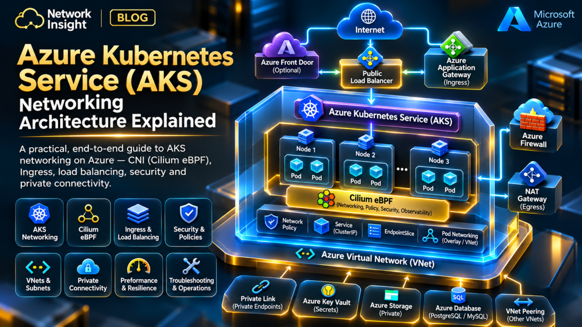
Azure Kubernetes Service Networking Architecture Explained
Understand how AKS connects Kubernetes workloads to Azure infrastructure through Azure CNI Overlay, Cilium eBPF, virtual networks, Services, load balancers, private networking and enterprise security controls.
Follow traffic from a Kubernetes pod through the node datapath and Azure network fabric. Explore how packets are routed, translated, filtered and delivered to applications in production.
Three Layers of AKS Networking
Production AKS networking spans Azure infrastructure, Kubernetes networking abstractions and the node datapath.
VNet, Subnets and Routing
Azure VNets, node subnets, NSGs, user-defined routes, load balancers, private connectivity and network security boundaries.
Pods, Services and DNS
Kubernetes pod addressing, service discovery, endpoints, ingress and cluster-level network configuration.
Azure CNI and Cilium
Container networking, packet processing, supported eBPF service handling, network policy enforcement and forwarding decisions.
Follow an AKS Network Traffic Path
Select an engineering scenario to understand how Azure infrastructure and Kubernetes networking components interact.
Traffic between Kubernetes pods is forwarded through the configured node networking datapath. Same-node communication can remain local, while cross-node communication depends on the selected AKS networking mode and node reachability.
What This Guide Will Teach You
Design AKS IP Architecture
Compare Azure CNI Overlay and Pod Subnet approaches, address allocation, subnet capacity and connectivity constraints.
Understand Packet Paths
Investigate pod-to-pod, Service, ingress, egress and hybrid network forwarding.
Apply Network Segmentation
Combine supported Cilium network policies, Azure NSGs, firewall controls and private access.
Troubleshoot Production AKS
Diagnose DNS, routing, NAT, load balancing, policy, MTU and datapath problems.
Engineer Resilience
Plan availability zones, node pools, application redundancy and network failure recovery.
Investigate eBPF Networking
Understand supported Cilium telemetry, flow diagnostics, service state and operational visibility.
Core engineering principle: AKS networking must be understood as an integrated system. Kubernetes decides the intended workload and Service state; Azure provides infrastructure connectivity; and the configured node datapath determines how packets are processed and forwarded.
Explore the Architecture.
Engineer the Network.
A complete engineering journey through Azure Kubernetes Service networking — from pod connectivity and Azure CNI Overlay to Cilium eBPF, Azure VNets, ingress, Zero Trust security, private clusters, high availability and production troubleshooting.
Nine Sections. One Complete AKS Networking System.
Select any section to jump directly into the architecture. The active section is highlighted automatically as you read.
AKS Networking Architecture Fundamentals
Managed control plane, worker nodes, Kubernetes networking layers and the complete AKS connectivity model.
Azure CNI Overlay and Pod IP Addressing
Pod CIDRs, node networking, overlay encapsulation, address planning and pod-to-pod packet delivery.
AKS Routing, Azure VNets and Hybrid Connectivity
Hub-and-spoke routing, VNet peering, UDRs, Azure Firewall and hybrid enterprise connectivity.
Services, Azure Load Balancers and Ingress
ClusterIP, NodePort, LoadBalancer, ingress controllers, Gateway API and backend selection.
AKS Network Security and Zero Trust
Cilium network policies, namespace isolation, default-deny security, NSGs and controlled egress.
Private AKS Clusters, DNS and Private Endpoints
Private API server access, Azure Private DNS, Private Link, DNS forwarding and hybrid management.
AKS Cilium eBPF Datapath and Observability
Kernel hooks, Service forwarding, endpoint identities, policy enforcement and packet diagnostics.
AKS High Availability and Multi-Region Networking
Availability zones, node pools, Azure Front Door, regional failover and disaster recovery.
AKS Production Troubleshooting and Performance
DNS failures, SNAT exhaustion, MTU mismatches, policy drops, Azure routing and incident investigation.
AKS Networking Architecture Fundamentals
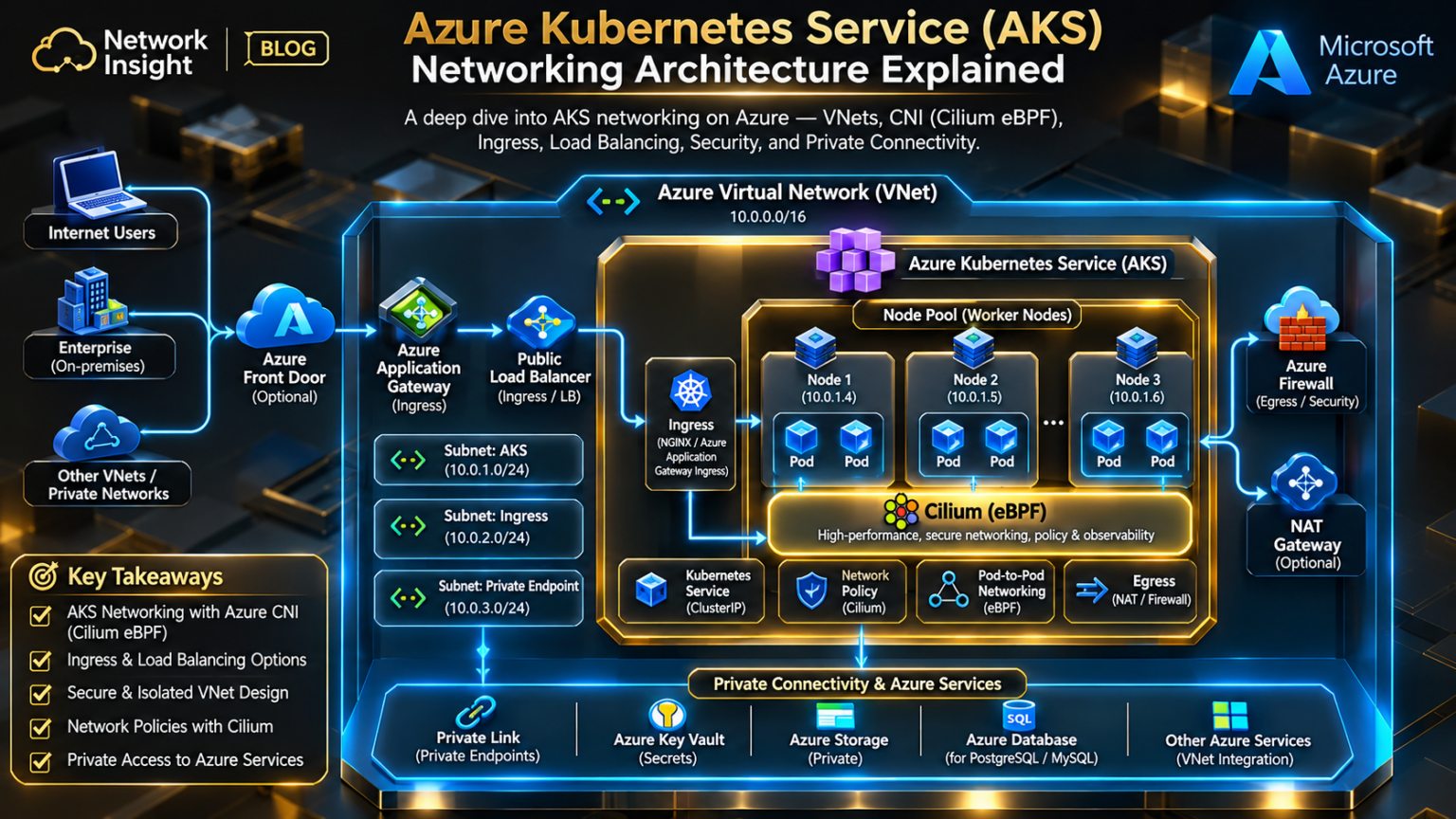
Azure Kubernetes Service combines the Kubernetes networking model with Azure virtual networking infrastructure to deliver scalable, secure and highly available container networking.
Understanding AKS networking requires engineers to separate the managed Kubernetes control plane, the worker-node infrastructure, and the pod and Service datapath.
These components interact continuously, but they perform different functions. The control plane maintains desired cluster state; Azure infrastructure supplies network connectivity; and the selected container networking implementation determines how application packets are processed.
The Relationship Between Azure Infrastructure and Kubernetes
AKS is a managed Kubernetes platform. Microsoft operates the managed control-plane components, while worker nodes run in Azure infrastructure associated with the cluster.
The networking architecture must support several distinct communication paths: control-plane management, pod-to-pod traffic, Service forwarding, application ingress, outbound internet access and connectivity to private enterprise networks.
Why the AKS Control Plane Is Separate From the Workload Datapath
The Kubernetes control plane maintains the desired state of the cluster. It manages workload scheduling, API operations, resource definitions and controller-driven reconciliation.
In AKS, Microsoft manages these control-plane components. Worker nodes communicate with the API server, but normal application traffic between pods does not need to traverse the API server.
Kubernetes API Server
Provides the API through which cluster resources are created, updated and observed. API access may be configured through supported public or private connectivity models.
Scheduler and Controllers
Coordinate desired cluster state, including workload placement and reconciliation. They do not forward application packets.
Worker Nodes
Host application pods and implement workload networking through the configured CNI, Linux kernel and supporting networking components.
Engineering distinction: A private AKS API server changes how the cluster is administered. It does not automatically make Kubernetes application Services private. API-server exposure and application ingress must be designed independently.
VNets, Node Subnets and Address Planning
AKS worker nodes connect to Azure virtual networking infrastructure. The node subnet provides addresses and connectivity for node interfaces, while pod address allocation depends on the selected networking mode.
Engineers must plan address ranges for nodes, pods, Kubernetes Services, private endpoints and connected enterprise networks. Overlapping CIDRs can complicate or prevent connectivity across VNets and hybrid networks.
| Address Domain | Purpose | Engineering Consideration |
|---|---|---|
| VNet address space | Azure network addressing boundary. | Avoid overlap with connected VNets and on-premises networks. |
| Node subnet | Addresses for AKS node interfaces and related infrastructure. | Allow for scaling, upgrades and temporary surge nodes. |
| Pod CIDR / pod subnet | Addresses assigned to application pods. | Allocation and routability depend on the Azure CNI mode. |
| Service CIDR | Virtual IP range for Kubernetes Services. | Keep separate from node, pod and connected network ranges. |
| Private endpoint subnet | Private connectivity to supported Azure services. | Plan DNS resolution, routing and access controls. |
Azure CNI Overlay Versus Pod Subnet Networking
Azure CNI supports different pod addressing architectures. The distinction between overlay and VNet-integrated pod addressing affects IP consumption, routing and how external systems communicate with pods.
| Capability | Azure CNI Overlay | Azure CNI Pod Subnet |
|---|---|---|
| Pod addresses | Allocated from an overlay CIDR separate from the VNet. | Allocated from a VNet-integrated pod subnet. |
| VNet IP consumption | Pods do not each consume a VNet address. | Pods consume addresses from the configured pod subnet. |
| Cross-node forwarding | Uses the supported overlay transport between nodes. | Uses the configured VNet-integrated forwarding model. |
| External reachability | Overlay pod IPs are not directly routable from external networks by default. | Pod IPs participate in the VNet addressing model, subject to routing and security. |
| Planning emphasis | Overlay CIDR sizing and node capacity. | Pod subnet capacity and address allocation strategy. |
Neither architecture eliminates the need to understand Service routing, NAT, security policies and external connectivity. The correct choice depends on application requirements, network scale and integration constraints.
Where Cilium eBPF Fits Into AKS Networking
Azure CNI Powered by Cilium integrates supported Cilium eBPF datapath functionality into AKS. This can include network policy enforcement and service handling, depending on the deployment configuration and supported platform capabilities.
Cilium does not replace Azure VNets, Azure routing infrastructure or the managed AKS control plane. Instead, it participates in the node-level networking implementation.
Packet Processing
Supported eBPF programs process traffic at Linux networking hooks and use kernel maps to support forwarding decisions.
Network Policies
Supported policy enforcement controls communication between workloads based on Kubernetes and Cilium networking constructs.
Observability
Operational visibility depends on the telemetry and diagnostic features exposed by the installed AKS networking implementation.
Which Component Owns the Network Decision?
Select a layer to inspect its responsibility in the AKS architecture.
The AKS control plane maintains Kubernetes API state and coordinates workload scheduling and reconciliation. It is not the normal forwarding path for pod application traffic.
Design Decisions That Shape AKS Network Reliability
Production AKS networking should be designed around application communication requirements rather than treating the default cluster deployment as a complete enterprise network architecture.
| Design Decision | Why It Matters |
|---|---|
| Azure CNI networking mode | Determines pod addressing, routing characteristics and IP consumption. |
| Node subnet sizing | Controls capacity for node growth, upgrades and autoscaling. |
| Ingress architecture | Defines how internal and external clients reach applications. |
| Outbound connectivity | Determines NAT behaviour, egress identity and firewall inspection paths. |
| Private API connectivity | Controls how authorised systems administer the cluster. |
| Network security policies | Controls permitted workload communication and network boundaries. |
| Observability | Provides evidence for packet drops, policy failures and routing incidents. |
Inspecting a Deployed AKS Cluster
Before troubleshooting individual packet flows, confirm the cluster networking configuration and the current Kubernetes resource state.
Compare the observed configuration with the intended design. Confirm pod address ranges, node subnet connectivity, Service CIDRs, cluster DNS and the configured outbound connectivity method.
Production engineering principle: Always identify the selected AKS network plugin, network plugin mode and datapath before applying troubleshooting guidance. Commands, supported features and forwarding behaviour can differ between Azure CNI configurations and AKS releases.
The AKS Networking Mental Model
AKS networking becomes easier to reason about when the architecture is separated into clear responsibilities:
Azure provides infrastructure connectivity. Kubernetes defines workloads and Services. Azure CNI integrates pod networking with the selected addressing model. Cilium, when enabled, implements supported eBPF datapath capabilities. Network policies and Azure security controls enforce their respective boundaries.
This foundation is essential before investigating packet forwarding, load balancing, private connectivity or production failures.
Azure Kubernetes Service Architecture Explorer
Explore how the Azure-managed Kubernetes control plane, AKS worker nodes, pod networks, Services, Azure VNets, and cloud infrastructure connect to form a production application platform.
Interactive AKS Technical Architecture
Select any component to inspect its engineering role. Run a traffic test to illuminate the relevant path.
AKS Networking Configuration
Infrastructure and Service Health
AKS Networking State Inspector
| Layer | Resource | State |
|---|
Packet Path Investigation
AKS Engineering Diagnostic Console
Architecture and Root Cause Analysis
Production Engineering Notes
In Azure CNI Overlay, pods use addresses from an overlay CIDR separate from the Azure VNet node subnet. Traffic leaving the cluster toward VNet or external destinations generally uses node-level address translation as appropriate to the traffic path.
In Azure CNI Pod Subnet mode, pod addresses are allocated from an Azure VNet pod subnet. This changes address planning, routing, and integration requirements compared with overlay networking.
A private AKS cluster uses a private API server endpoint and requires suitable private network connectivity and DNS resolution for management access. This is separate from whether application Services are public or private.
Azure CNI Powered by Cilium provides an eBPF-based datapath for supported AKS configurations. Specific features and combinations depend on current AKS networking support and cluster configuration.
Educational simulation. Topology, IP addresses, failure states, and packet traces are illustrative. This widget does not provision Azure resources or connect to a live AKS cluster.
Azure CNI Overlay and Pod IP Addressing
Azure CNI networking determines how Kubernetes pods receive IP addresses, how packets cross node boundaries and how workloads communicate with Azure VNets and external networks.
In Azure CNI Overlay, pods receive addresses from a separate overlay address space rather than consuming individual addresses from the Azure VNet subnet. Nodes remain connected through their Azure VNet interfaces.
Understanding this separation is fundamental to designing scalable AKS clusters and troubleshooting cross-node connectivity, routing and source NAT behaviour.
How Azure CNI Overlay Separates Pod and Node Addressing
Azure CNI Overlay uses a pod address range that is logically separate from the Azure VNet address space. Each node receives a pod CIDR allocation, while its node interface uses an IP address from the configured Azure subnet.
Cross-node pod traffic is transported between nodes through the overlay implementation. The underlay network needs connectivity between node addresses, while the container networking layer handles the pod-to-pod path.
Pod CIDRs, Node IPs and Service Address Space
AKS networking uses multiple IP address domains. Engineers should avoid treating the node subnet, pod range and Kubernetes Service range as interchangeable.
| Address Domain | Illustrative CIDR | Purpose |
|---|---|---|
| Azure VNet | 10.10.0.0/16 | Azure network infrastructure. |
| AKS node subnet | 10.10.1.0/24 | Node interfaces and associated infrastructure. |
| Azure CNI Overlay pod range | 192.168.0.0/16 | Pod addresses allocated from the overlay range. |
| Node A pod CIDR | 192.168.0.0/24 | Example pod allocation assigned to Node A. |
| Node B pod CIDR | 192.168.1.0/24 | Example pod allocation assigned to Node B. |
| Kubernetes Service CIDR | 172.20.0.0/16 | Virtual addresses used by Kubernetes Services. |
These ranges are illustrative rather than recommended defaults. Actual CIDRs must be planned against enterprise addressing, supported AKS requirements, connected networks and expected scale.
Tracing Pod Traffic Between AKS Nodes
Consider a packet sent from Pod A on Node A to Pod C on Node B. The packet enters the configured node datapath, which determines the destination pod location and forwards traffic through the overlay transport.
The exact implementation depends on the selected Azure CNI mode and datapath. Engineers should inspect actual interfaces, routes and packet captures rather than assuming every AKS configuration uses the same Linux forwarding path.
Why External Destinations Often See the Node IP
With Azure CNI Overlay, traffic leaving the overlay for destinations outside the pod CIDR is generally source-NATed to the node IP, subject to supported exceptions and network configuration.
This distinction matters for firewall rules, connection logging, application allowlists and troubleshooting. An external destination may see a node address or a further translated outbound address rather than the original pod address.
Pod Source Address
The application originates traffic using its assigned overlay IP address.
Node Translation
The supported outbound datapath translates the source address for traffic leaving the overlay.
Azure Egress
Additional Azure NAT, firewall or routing infrastructure may determine the final source address visible externally.
Operational distinction: Pod-to-pod overlay forwarding and outbound internet egress are different traffic cases. Do not assume that a packet follows the same NAT or routing path simply because it originates from the same pod.
Azure CNI Overlay Versus VNet-Integrated Pod Subnets
| Engineering Property | Azure CNI Overlay | Azure CNI Pod Subnet |
|---|---|---|
| Pod addressing | Separate overlay CIDR. | VNet-integrated pod subnet. |
| VNet IP consumption | Pod IPs do not individually consume VNet addresses. | Pod IPs consume addresses from the configured subnet. |
| Cross-node communication | Uses the supported overlay transport. | Uses the configured VNet-integrated networking model. |
| External access to pod IPs | Not directly routable from external networks by default. | Potentially routable within connected networks, subject to routing and security. |
| Capacity planning | Overlay CIDR and node allocations. | Pod subnet allocation and address availability. |
| Primary design tradeoff | Address efficiency versus overlay constraints. | VNet integration versus VNet IP consumption. |
Understand AKS Addressing and Forwarding Decisions
Select a scenario to inspect the expected logical packet path.
Pods use addresses from the overlay CIDR. The configured node datapath transports cross-node traffic using node-level connectivity while preserving the logical pod-to-pod communication model.
Designing Pod Address Space for Cluster Growth
Pod addressing must account for current workloads, cluster autoscaling, node pool expansion and upgrade operations.
For Azure CNI Overlay configurations that allocate a /24 pod CIDR per node, a /16 overlay range provides 256 distinct /24 blocks in arithmetic terms. This is not a guarantee of 256 usable production nodes: platform limits, reservations and operational capacity must also be considered.
Capacity engineering: Address space should be sized for the cluster's lifecycle, not just its initial node count. Validate current Azure CNI Overlay constraints and AKS version-specific scaling limits before deployment.
Investigating Pod Addressing and Overlay Connectivity
| Symptom | Possible Cause | Investigation |
|---|---|---|
| Pod remains Pending | Scheduling or capacity problem. | Inspect pod events, node resources and scheduling constraints. |
| Pod sandbox creation fails | CNI or IP allocation failure. | Inspect pod events and networking component logs. |
| Same-node works, cross-node fails | Overlay transport or node reachability problem. | Validate node IP connectivity and network restrictions. |
| Pod cannot reach external destination | SNAT, Azure routing, NSG or egress failure. | Trace node and Azure outbound paths. |
| Only certain destination ranges fail | Overlapping CIDRs or route conflicts. | Compare pod, Service, VNet and enterprise ranges. |
Do not change routes or restart networking components until the failure domain is identified. First establish whether the problem affects one pod, one node, a node pool or the entire cluster.
The Azure CNI Overlay Mental Model
Pods have overlay addresses. Nodes have Azure VNet addresses. The configured datapath connects those two addressing domains.
Cross-node forwarding depends on node connectivity and the overlay transport, while communication outside the overlay introduces additional routing and NAT considerations.
Understanding these boundaries makes it easier to design scalable clusters and investigate failures involving pod addressing, Azure routing and external connectivity.
Azure CNI Packet Path Simulator
Investigate Azure CNI Overlay and Pod Subnet networking. Trace packets across AKS worker nodes, inspect encapsulation and address translation, and evaluate IP allocation, routing and MTU behavior.
Azure CNI Packet Architecture
The diagram illustrates node transport and pod addressing. Overlay encapsulation and VNet-routable pod addresses represent different forwarding architectures.
Packet Engineering Console
Datapath Health
Pod IP Allocation Calculator
| Parameter | Calculated Value |
|---|
Packet Processing Pipeline
Azure CNI Diagnostic Terminal
Packet Header Transformation Inspector
Production Engineering Notes
Azure CNI Overlay assigns pod addresses from an overlay address space separate from the node subnet. Cross-node pod communication uses an encapsulated transport between nodes. For traffic leaving the cluster, source address translation may use the node IP before Azure outbound networking applies further translation.
Azure CNI Pod Subnet allocates pod addresses from a VNet subnet. Pod address capacity and subnet planning differ from overlay networking. Pod Subnet implementations may use different allocation approaches, including dynamic IP allocation or static block allocation, depending on configuration.
Effective MTU must account for encapsulation overhead, underlying network MTU and the selected datapath. Packet loss caused by MTU mismatch should be investigated using appropriately sized probes and path-level diagnostics.
Educational simulation only. Address ranges, allocation figures, SNAT behavior and packet transformations are simplified to illustrate architectural differences. The calculator does not replace AKS capacity-planning documentation.
AKS Routing, Azure VNets and Hybrid Connectivity
AKS networking extends beyond pod communication. Production clusters must exchange traffic with Azure services, connected VNets, enterprise data centres, private endpoints and external networks.
Azure provides the infrastructure routing domain through virtual networks, system routes, user-defined routes, VNet peering and hybrid gateways. Kubernetes and the selected CNI implementation handle workload networking within that infrastructure.
The engineering challenge is to understand how these routing layers interact without introducing asymmetric paths, unreachable address ranges, unexpected source NAT or security-policy conflicts.
AKS in a Hub-and-Spoke Azure Network
A common enterprise design places AKS in a spoke VNet connected to a shared networking hub. The hub can provide centralised firewall inspection, hybrid gateways, DNS infrastructure and connectivity to other application networks.
This architecture separates application infrastructure from shared network services. However, VNet peering alone does not create automatic transitive routing between every connected spoke.
System Routes, User-Defined Routes and Effective Routing
Azure virtual networking uses system routes and can incorporate user-defined routes and routes propagated through supported gateway configurations.
When routing decisions are made, longest-prefix matching is fundamental. For routes with identical address prefixes, Azure applies its documented route-source priority rules.
System Routes
Azure supplies default routes for VNet connectivity and other platform-defined destinations.
User-Defined Routes
Custom routes can direct selected traffic toward supported next hops such as Azure Firewall or a network virtual appliance.
Gateway-Propagated Routes
Hybrid connectivity can introduce routes learned through supported gateway and BGP configurations.
| Route Type | Example | Engineering Purpose |
|---|---|---|
| System VNet route | 10.20.0.0/16 → Virtual network | Local VNet connectivity. |
| UDR default route | 0.0.0.0/0 → Firewall private IP | Controlled outbound traffic. |
| Specific UDR | 10.50.0.0/16 → Virtual appliance | Selected enterprise network forwarding. |
| Gateway route | 172.16.0.0/16 → Virtual network gateway | Hybrid network reachability. |
| Peering route | 10.30.0.0/16 → VNet peering | Connected VNet address-space reachability. |
Important: A UDR on the AKS node subnet influences Azure infrastructure forwarding for applicable traffic. It does not replace Kubernetes Service forwarding, CNI pod routing or network policy enforcement.
Connecting AKS Spokes to Shared Azure Infrastructure
VNet peering allows connected Azure virtual networks to communicate over Azure's private network infrastructure, subject to routing and security configuration.
A common deployment connects the AKS spoke to a central hub containing Azure Firewall, DNS resolvers, hybrid gateways and shared services.
| Peering Consideration | Production Implication |
|---|---|
| Address-space overlap | Overlapping VNet ranges prevent normal peering between those VNets. |
| Non-transitive peering | Spoke A does not automatically reach Spoke B through a common hub. |
| Gateway transit | Requires supported peering and gateway configuration. |
| Forwarded traffic | Must be permitted and routed appropriately where appliances forward traffic. |
| Return path | Bidirectional routing and security rules must be validated. |
Routing AKS Egress Through Centralised Security
Enterprises frequently require outbound AKS traffic to pass through centralised inspection infrastructure. This may involve Azure Firewall, a supported network virtual appliance or another approved egress design.
A user-defined route can direct applicable node-subnet traffic to a firewall next hop. The complete design must also account for the selected AKS outbound type, source NAT, platform dependencies and required destination access.
Forced-tunnelling and firewall architectures must follow the supported AKS networking requirements. A default route alone does not guarantee that every packet or platform dependency will follow the intended path.
ExpressRoute, VPN and Enterprise Network Integration
AKS applications often need access to enterprise databases, authentication services, monitoring systems or other workloads hosted outside Azure.
Azure ExpressRoute and site-to-site VPN provide different connectivity options for linking enterprise networks with Azure VNets.
ExpressRoute
Provides private connectivity through an ExpressRoute service provider or supported connectivity arrangement, with routing integrated into the Azure hybrid architecture.
Site-to-Site VPN
Uses encrypted IPsec tunnels over IP connectivity to connect enterprise networks to supported Azure VPN gateway configurations.
Centralised Hub Routing
Provides shared routing and security functions for connected spokes, subject to explicit transit and forwarding configuration.
Overlay consideration: In Azure CNI Overlay, external networks do not normally route directly to pod overlay addresses. Application access should use supported Service, ingress, proxy or other connectivity patterns rather than assuming pod CIDRs are reachable through ExpressRoute or VPN.
Trace AKS Traffic Across Azure and Hybrid Networks
Select a traffic scenario to inspect the logical forwarding path and the engineering checks required.
Traffic from an AKS workload reaches a destination in the connected Azure VNet through the configured CNI datapath and Azure infrastructure routing. Overlay deployments generally apply source NAT for destinations outside the overlay range, subject to supported exceptions.
Common AKS Routing Problems in Production
| Failure Symptom | Likely Investigation Area | Engineering Action |
|---|---|---|
| AKS cannot reach another spoke | Non-transitive peering or missing transit route. | Validate route tables, forwarding and hub configuration. |
| Hybrid application unreachable | Missing gateway route, firewall rule or return path. | Check effective routes and enterprise routing. |
| Only some destinations fail | Prefix overlap, route specificity or security policy. | Compare effective routes and address ranges. |
| Outbound traffic fails after UDR change | Incorrect next hop or missing platform dependencies. | Inspect AKS outbound configuration and firewall logs. |
| Private endpoint resolves incorrectly | DNS zone or resolver configuration. | Validate private DNS resolution from the workload. |
| Connections fail intermittently | Asymmetric routing, NAT or stateful inspection. | Trace both directions of the flow. |
Inspecting AKS and Azure Routing State
The effective-route command applies to supported Azure VM network interfaces. AKS-managed node interfaces may have access restrictions or lifecycle considerations, so confirm the node resource group and the appropriate supported diagnostic method before running investigations.
Production troubleshooting principle: Always validate the forward and return paths. A route that successfully sends packets toward a destination does not prove that the destination can return traffic through the expected NAT, firewall and hybrid connectivity architecture.
The AKS Hybrid Routing Mental Model
Kubernetes determines workload connectivity intent. The CNI datapath forwards pod traffic. Azure VNets, route tables, peering, gateways and security appliances determine how applicable traffic moves through the infrastructure.
Reliable enterprise AKS connectivity depends on consistent address planning, supported transit design, correct route selection, DNS resolution, security enforcement and symmetric return-path handling.
AKS Routing Path Explorer
Trace AKS application traffic through Azure VNets, user-defined routes, hub-spoke connectivity, Azure Firewall and enterprise hybrid networks. Investigate routing failures, asymmetric paths, security enforcement and next-hop selection.
Azure AKS Hub-Spoke Routing Architecture
Select a network component to inspect its role. Trace traffic between AKS, the Azure hub, and on-premises infrastructure.
Azure Routing Engineering Console
Routing and Security State
Azure Effective Route Table
| Prefix | Source | Next Hop | State |
|---|
Routing Decision Pipeline
Azure Routing Diagnostic Terminal
Root Cause and Path Interpretation
Production Engineering Notes
Azure routing uses longest-prefix matching. For equally specific routes, Azure applies route-source precedence rules. User-defined routes can override system or BGP routes where applicable, but more-specific routes may still win.
VNet peering provides private connectivity between peered VNets, subject to configuration, security rules and route behavior. Peering is not automatically transitive; hub-spoke designs require deliberate routing and gateway-transit configuration.
ExpressRoute and site-to-site VPN can provide hybrid connectivity, but the appropriate gateway, learned prefixes, route propagation, and return routing must all be considered.
Azure Firewall insertion requires careful consideration of source and destination routes, application requirements, security policy and potential asymmetric forwarding. A healthy forward route does not guarantee a healthy return path.
Educational routing simulation. The effective route table and packet traces are illustrative and do not query Azure. Actual routing depends on deployed subnets, route tables, peering settings, gateways, BGP advertisements and Azure platform behavior.
AKS Services, Azure Load Balancers and Ingress Architecture
Kubernetes Services provide stable network identities for dynamic application workloads, while Azure load balancing and ingress infrastructure connect those workloads to clients inside and outside the cluster.
AKS application connectivity spans several forwarding layers: Kubernetes Service virtual IPs, backend EndpointSlices, node datapaths, Azure Standard Load Balancer and optional Layer 7 ingress or Gateway implementations.
Understanding these layers is essential for designing reliable application delivery and troubleshooting connection failures, unhealthy backends, incorrect traffic policies and unexpected source NAT.
How External Traffic Reaches an AKS Application
A common AKS deployment exposes applications through a Kubernetes LoadBalancer Service or an ingress controller fronted by an Azure load balancer.
The exact forwarding path depends on the Service type, ingress implementation, datapath and traffic policy. An ingress controller or Gateway provides application-layer routing, whereas an Azure Standard Load Balancer primarily performs Layer 4 load balancing.
ClusterIP, NodePort and LoadBalancer
Kubernetes Services provide stable network abstractions for workloads whose pod addresses may change during scaling, rescheduling and deployment operations.
ClusterIP
Exposes a Service through a virtual cluster IP for internal connectivity. It does not independently create an externally accessible Azure load balancer.
NodePort
Exposes a Service through a port on eligible node addresses, subject to network reachability and firewall rules.
LoadBalancer
Requests external load-balancing infrastructure through the supported cloud integration. In AKS this commonly provisions Azure Standard Load Balancer resources.
| Service Type | Primary Access Model | AKS Networking Implication |
|---|---|---|
| ClusterIP | Internal Service virtual IP. | Handled by the configured Kubernetes Service datapath. |
| NodePort | Node address and allocated Service port. | Requires appropriate node reachability and traffic policy. |
| LoadBalancer | Azure load balancer frontend. | Requires supported Azure cloud integration, backend configuration and health probes. |
| ExternalName | DNS alias to an external hostname. | DNS mapping rather than a conventional Service proxy or Azure load balancer. |
Frontend IPs, Backend Pools and Health Probes
Azure Standard Load Balancer distributes supported Layer 4 traffic using configured frontend IPs, rules, backend pools and health probes.
In AKS, the Kubernetes cloud integration coordinates supported Azure load balancer resources for LoadBalancer Services. The backend architecture and node traffic handling depend on the cluster and Service configuration.
Public or Internal IP
Defines the address clients use to reach the application. Internal load balancers provide private frontend addresses.
Eligible Node Backends
Azure forwards traffic to healthy backend targets according to the load-balancing configuration.
Health Probe State
Health probes determine backend eligibility. Probe configuration must align with the Service and traffic policy.
Important distinction: An Azure load balancer health probe does not replace Kubernetes application readiness checks. A node may be eligible at the Azure load-balancing layer while individual application endpoints have separate readiness state.
Layer 7 Routing Above Kubernetes Services
Ingress controllers provide HTTP and HTTPS routing capabilities such as hostname matching, path routing and TLS termination.
Gateway API provides a more expressive Kubernetes resource model for supported traffic-management implementations. It separates gateway infrastructure from route definitions and supports different ownership and delegation patterns.
| Capability | Ingress | Gateway API |
|---|---|---|
| Routing resources | Ingress resources interpreted by a controller. | Gateway, HTTPRoute and other supported route resources. |
| Implementation | Requires an ingress controller. | Requires a compatible Gateway API controller. |
| HTTP routing | Host and path routing. | Expressive matching and routing based on implementation support. |
| Role separation | Typically controller-specific. | Designed for infrastructure and application role separation. |
| Azure integration | Depends on the selected ingress implementation. | Depends on the selected Gateway controller and supported Azure integration. |
Neither an Ingress resource nor a Gateway API resource forwards packets by itself. A compatible controller must implement the configuration and operate the associated traffic-processing infrastructure.
EndpointSlices, Readiness and Service Datapath Forwarding
Kubernetes EndpointSlices represent backend endpoints associated with Services. Controllers update endpoint information as pods become ready, scale or terminate.
The configured Kubernetes Service datapath uses this state to forward traffic to eligible destinations. Depending on AKS networking configuration, the implementation may use supported Cilium eBPF mechanisms or other Service forwarding components.
externalTrafficPolicy, Source IP and Local Backends
Kubernetes Service traffic policies influence how external traffic is forwarded and whether the original client source IP can be preserved.
| Configuration | Typical Behaviour | Engineering Tradeoff |
|---|---|---|
| externalTrafficPolicy: Cluster | Traffic may be forwarded to eligible endpoints on other nodes. | Broader backend reachability; source IP handling depends on the path. |
| externalTrafficPolicy: Local | External Service traffic uses node-local eligible endpoints. | Can preserve client source IP, but requires careful backend and health-probe design. |
| internalTrafficPolicy: Cluster | Internal traffic may use eligible endpoints across the cluster. | Supports cluster-wide backend selection. |
| internalTrafficPolicy: Local | Internal traffic is restricted to eligible node-local endpoints. | Traffic may fail when no local eligible endpoint exists. |
Production design principle: Do not enable Local traffic policies solely to preserve source IP without understanding node placement, health probes, backend distribution and the behaviour of the selected AKS datapath.
Trace Kubernetes Service and Ingress Traffic
Select a scenario to understand the forwarding layers and operational dependencies.
A pod connects to a Kubernetes Service virtual IP. The configured Service datapath selects an eligible backend from the current endpoint state and forwards the connection to the destination pod.
Inspecting Services, Endpoints and Ingress Resources
Gateway API commands require the relevant custom resource definitions. Azure load balancer inspection requires access to the correct resource group and sufficient Azure permissions.
Diagnosing Application Delivery Failures
| Symptom | Likely Investigation Area | Recommended Check |
|---|---|---|
| Service has no endpoints | Selector mismatch or pod readiness. | Inspect EndpointSlices and pod labels. |
| LoadBalancer IP remains pending | Azure resource provisioning or permissions. | Inspect Service events and cloud resource state. |
| External connections time out | NSG, load balancer, backend or policy problem. | Check frontend rules, probes and node reachability. |
| HTTP 404 through ingress | Host or path routing mismatch. | Inspect ingress rules and controller logs. |
| HTTP 502 or 503 | Backend reachability or health problem. | Inspect controller logs, Services and endpoint readiness. |
| Source IP differs from expectation | SNAT, proxy or traffic policy. | Trace each forwarding layer and headers where applicable. |
| Intermittent application failures | Backend churn, health probes or uneven placement. | Correlate endpoint changes with load balancer health. |
Engineering troubleshooting rule: Separate Layer 4 reachability from Layer 7 application routing. A healthy Azure load balancer does not prove that an ingress route, Kubernetes Service or backend application is functioning correctly.
The AKS Application Delivery Mental Model
Azure load balancers provide infrastructure-level traffic distribution. Kubernetes Services provide stable workload connectivity. Ingress controllers and Gateway implementations provide application-layer routing. EndpointSlices and the configured datapath connect Services to eligible pods.
Production reliability depends on correct frontend configuration, backend health, readiness, traffic policies, network security and observability across every layer.
AKS Services, Azure Load Balancers and Ingress Architecture
Kubernetes Services provide stable network identities for dynamic application workloads, while Azure load balancing and ingress infrastructure connect those workloads to clients inside and outside the cluster.
AKS application connectivity spans several forwarding layers: Kubernetes Service virtual IPs, backend EndpointSlices, node datapaths, Azure Standard Load Balancer and optional Layer 7 ingress or Gateway implementations.
Understanding these layers is essential for designing reliable application delivery and troubleshooting connection failures, unhealthy backends, incorrect traffic policies and unexpected source NAT.
How External Traffic Reaches an AKS Application
A common AKS deployment exposes applications through a Kubernetes LoadBalancer Service or an ingress controller fronted by an Azure load balancer.
The exact forwarding path depends on the Service type, ingress implementation, datapath and traffic policy. An ingress controller or Gateway provides application-layer routing, whereas an Azure Standard Load Balancer primarily performs Layer 4 load balancing.
ClusterIP, NodePort and LoadBalancer
Kubernetes Services provide stable network abstractions for workloads whose pod addresses may change during scaling, rescheduling and deployment operations.
ClusterIP
Exposes a Service through a virtual cluster IP for internal connectivity. It does not independently create an externally accessible Azure load balancer.
NodePort
Exposes a Service through a port on eligible node addresses, subject to network reachability and firewall rules.
LoadBalancer
Requests external load-balancing infrastructure through the supported cloud integration. In AKS this commonly provisions Azure Standard Load Balancer resources.
| Service Type | Primary Access Model | AKS Networking Implication |
|---|---|---|
| ClusterIP | Internal Service virtual IP. | Handled by the configured Kubernetes Service datapath. |
| NodePort | Node address and allocated Service port. | Requires appropriate node reachability and traffic policy. |
| LoadBalancer | Azure load balancer frontend. | Requires supported Azure cloud integration, backend configuration and health probes. |
| ExternalName | DNS alias to an external hostname. | DNS mapping rather than a conventional Service proxy or Azure load balancer. |
Frontend IPs, Backend Pools and Health Probes
Azure Standard Load Balancer distributes supported Layer 4 traffic using configured frontend IPs, rules, backend pools and health probes.
In AKS, the Kubernetes cloud integration coordinates supported Azure load balancer resources for LoadBalancer Services. The backend architecture and node traffic handling depend on the cluster and Service configuration.
Public or Internal IP
Defines the address clients use to reach the application. Internal load balancers provide private frontend addresses.
Eligible Node Backends
Azure forwards traffic to healthy backend targets according to the load-balancing configuration.
Health Probe State
Health probes determine backend eligibility. Probe configuration must align with the Service and traffic policy.
Important distinction: An Azure load balancer health probe does not replace Kubernetes application readiness checks. A node may be eligible at the Azure load-balancing layer while individual application endpoints have separate readiness state.
Layer 7 Routing Above Kubernetes Services
Ingress controllers provide HTTP and HTTPS routing capabilities such as hostname matching, path routing and TLS termination.
Gateway API provides a more expressive Kubernetes resource model for supported traffic-management implementations. It separates gateway infrastructure from route definitions and supports different ownership and delegation patterns.
| Capability | Ingress | Gateway API |
|---|---|---|
| Routing resources | Ingress resources interpreted by a controller. | Gateway, HTTPRoute and other supported route resources. |
| Implementation | Requires an ingress controller. | Requires a compatible Gateway API controller. |
| HTTP routing | Host and path routing. | Expressive matching and routing based on implementation support. |
| Role separation | Typically controller-specific. | Designed for infrastructure and application role separation. |
| Azure integration | Depends on the selected ingress implementation. | Depends on the selected Gateway controller and supported Azure integration. |
Neither an Ingress resource nor a Gateway API resource forwards packets by itself. A compatible controller must implement the configuration and operate the associated traffic-processing infrastructure.
EndpointSlices, Readiness and Service Datapath Forwarding
Kubernetes EndpointSlices represent backend endpoints associated with Services. Controllers update endpoint information as pods become ready, scale or terminate.
The configured Kubernetes Service datapath uses this state to forward traffic to eligible destinations. Depending on AKS networking configuration, the implementation may use supported Cilium eBPF mechanisms or other Service forwarding components.
externalTrafficPolicy, Source IP and Local Backends
Kubernetes Service traffic policies influence how external traffic is forwarded and whether the original client source IP can be preserved.
| Configuration | Typical Behaviour | Engineering Tradeoff |
|---|---|---|
| externalTrafficPolicy: Cluster | Traffic may be forwarded to eligible endpoints on other nodes. | Broader backend reachability; source IP handling depends on the path. |
| externalTrafficPolicy: Local | External Service traffic uses node-local eligible endpoints. | Can preserve client source IP, but requires careful backend and health-probe design. |
| internalTrafficPolicy: Cluster | Internal traffic may use eligible endpoints across the cluster. | Supports cluster-wide backend selection. |
| internalTrafficPolicy: Local | Internal traffic is restricted to eligible node-local endpoints. | Traffic may fail when no local eligible endpoint exists. |
Production design principle: Do not enable Local traffic policies solely to preserve source IP without understanding node placement, health probes, backend distribution and the behaviour of the selected AKS datapath.
Trace Kubernetes Service and Ingress Traffic
Select a scenario to understand the forwarding layers and operational dependencies.
A pod connects to a Kubernetes Service virtual IP. The configured Service datapath selects an eligible backend from the current endpoint state and forwards the connection to the destination pod.
Inspecting Services, Endpoints and Ingress Resources
Gateway API commands require the relevant custom resource definitions. Azure load balancer inspection requires access to the correct resource group and sufficient Azure permissions.
Diagnosing Application Delivery Failures
| Symptom | Likely Investigation Area | Recommended Check |
|---|---|---|
| Service has no endpoints | Selector mismatch or pod readiness. | Inspect EndpointSlices and pod labels. |
| LoadBalancer IP remains pending | Azure resource provisioning or permissions. | Inspect Service events and cloud resource state. |
| External connections time out | NSG, load balancer, backend or policy problem. | Check frontend rules, probes and node reachability. |
| HTTP 404 through ingress | Host or path routing mismatch. | Inspect ingress rules and controller logs. |
| HTTP 502 or 503 | Backend reachability or health problem. | Inspect controller logs, Services and endpoint readiness. |
| Source IP differs from expectation | SNAT, proxy or traffic policy. | Trace each forwarding layer and headers where applicable. |
| Intermittent application failures | Backend churn, health probes or uneven placement. | Correlate endpoint changes with load balancer health. |
Engineering troubleshooting rule: Separate Layer 4 reachability from Layer 7 application routing. A healthy Azure load balancer does not prove that an ingress route, Kubernetes Service or backend application is functioning correctly.
The AKS Application Delivery Mental Model
Azure load balancers provide infrastructure-level traffic distribution. Kubernetes Services provide stable workload connectivity. Ingress controllers and Gateway implementations provide application-layer routing. EndpointSlices and the configured datapath connect Services to eligible pods.
Production reliability depends on correct frontend configuration, backend health, readiness, traffic policies, network security and observability across every layer.
AKS Service Traffic Simulator
Investigate Kubernetes Service exposure, Azure Load Balancer forwarding, ingress routing, Gateway API concepts, backend selection, source-IP preservation and application availability.
AKS Application Traffic Architecture
Select any architecture component to inspect its role. The active packet path changes according to the Service exposure mode and simulated failure.
Service Engineering Console
Application Health and Routing
Kubernetes Service and Endpoint State
| Resource | Address | Role | State |
|---|
Application Packet Processing
AKS Service Diagnostic Terminal
Traffic Engineering and Root Cause
Production Engineering Notes
A Kubernetes ClusterIP Service provides a stable virtual address for a group of backend endpoints. NodePort exposes a Service through a port on eligible cluster nodes. LoadBalancer Services integrate with Azure Load Balancer when supported by the cluster configuration.
Ingress controllers and Gateway API implementations provide application-level routing capabilities, but the Kubernetes resources alone do not create a working data plane. A controller or gateway implementation must be deployed and configured.
For externalTrafficPolicy: Local, only nodes with suitable local endpoints can serve external traffic. This can preserve the original client source IP for supported paths, but it requires careful attention to Azure Load Balancer health probes, backend distribution and node-level availability.
With externalTrafficPolicy: Cluster, Service traffic may be forwarded to endpoints on other nodes. Client source-IP visibility depends on the actual Service datapath and translation behavior.
Educational browser-only simulation. Backend selection and probe behavior are simplified. Real AKS implementations depend on the selected network datapath, Azure Load Balancer configuration, Kubernetes endpoint readiness and controller behavior.
AKS Network Security and Zero Trust Architecture
Securing AKS requires more than protecting the Azure VNet perimeter. Production Kubernetes environments need workload-level segmentation, controlled ingress and egress, identity-aware access and consistent enforcement across Azure and Kubernetes networking layers.
Azure provides infrastructure security through network security groups, Azure Firewall, private connectivity and identity services. Kubernetes network policies and supported Cilium datapath capabilities provide additional workload-level controls.
The central engineering objective is to enforce least-privilege connectivity while preserving the communication paths applications require to function.
Layered Enforcement Across Azure and Kubernetes
AKS network security is a layered architecture. A packet can encounter workload policy enforcement, node networking, Azure subnet controls, routing infrastructure and centralised firewall inspection.
These controls operate at different boundaries. An NSG does not replace a Kubernetes NetworkPolicy, and a Kubernetes NetworkPolicy does not replace enterprise egress inspection.
Default-Deny and Explicitly Allowed Workload Traffic
Kubernetes NetworkPolicy resources select pods and define permitted ingress and egress communication. Once a pod is isolated for a direction, only traffic allowed by applicable policies is permitted in that direction.
Network policies are additive. Multiple policies selecting the same pod contribute to the set of allowed connections rather than being evaluated as a simple ordered firewall rule list.
This policy isolates pods in the production namespace for both directions. It should be introduced with explicit allow policies for required DNS, monitoring, application and platform communication.
Policy design warning: Applying default-deny egress without permitting required DNS and application dependencies can cause widespread service failures. Validate the actual traffic requirements before enforcing the policy.
Allowing Frontend-to-Backend Traffic Without Broad Trust
Namespace labels and pod labels allow engineers to define precise workload communication rules. For example, a backend API can permit requests only from approved frontend workloads.
The namespaceSelector and podSelector in the same peer entry are combined, so the source must match both. The policy governs ingress to selected backend pods; a separately isolated frontend also needs an appropriate egress allow rule.
Network Policy Enforcement in the Node Datapath
Azure CNI Powered by Cilium can enforce supported Kubernetes network policies through its eBPF-based datapath.
Cilium uses endpoint identity and policy information to evaluate permitted traffic. Exact enforcement hooks, observability tools and supported policy features depend on the AKS deployment and platform version.
Pod Identity and Labels
Labels and selectors define which workloads a policy applies to and which peers are permitted.
eBPF Policy Enforcement
Supported Cilium datapath functions evaluate workload traffic against installed policy state.
Policy Observability
Available diagnostics can help distinguish policy drops from routing, DNS or application failures.
AKS compatibility: Do not assume that every upstream Cilium feature or custom Cilium policy resource is supported in managed AKS. Confirm the capabilities and support boundaries of Azure CNI Powered by Cilium for the deployed version.
NSGs, Azure Firewall and Private Connectivity
| Security Layer | Primary Responsibility | Engineering Consideration |
|---|---|---|
| Kubernetes NetworkPolicy | Pod-level ingress and egress permissions. | Selectors, isolation directions and required application flows. |
| Cilium datapath | Supported workload policy enforcement. | AKS compatibility, policy state and available diagnostics. |
| Azure NSG | Subnet and network-interface traffic filtering. | Node reachability, ingress, egress and platform requirements. |
| Azure Firewall | Centralised network and application rule enforcement. | UDRs, NAT, DNS, rule priorities and return paths. |
| Private Endpoint | Private IP connectivity to supported Azure services. | DNS resolution, service access controls and network reachability. |
| Private AKS API | Private control-plane access. | Administrative network access and private DNS. |
These mechanisms are complementary. A robust design applies each control to the boundary it can reliably enforce rather than relying on one product to provide complete Zero Trust security.
Why DNS Must Be Included in Network Policy Design
Many Kubernetes workloads depend on cluster DNS for Service discovery and external hostname resolution.
When egress isolation is enabled, DNS traffic must be permitted to the appropriate resolver endpoints. The exact rules depend on the cluster DNS implementation, labels, namespaces and network path.
A policy that permits TCP 443 to an external service may still fail if the application cannot resolve the destination hostname.
Evaluate AKS Workload Communication Scenarios
Select a scenario to inspect the expected policy decision and the relevant enforcement boundary.
A backend ingress policy permits matching frontend pods from an approved namespace to reach TCP port 8080. The connection also requires source egress permission if the frontend is egress-isolated.
Inspecting AKS Network Security State
The availability of Cilium-specific diagnostic commands depends on the managed AKS networking configuration. Use supported cluster and Azure diagnostics rather than assuming unrestricted access to upstream Cilium tooling.
Diagnosing Policy and Connectivity Failures
| Symptom | Likely Cause | Investigation |
|---|---|---|
| Backend unreachable after policy change | Missing ingress or source egress allow rule. | Inspect policy selectors and both traffic directions. |
| DNS fails after default-deny | DNS egress not permitted. | Check resolver endpoints and UDP/TCP 53 permissions. |
| External API unreachable | Policy, NSG, firewall or routing restriction. | Trace workload and Azure security boundaries. |
| Only one namespace is affected | Namespace selector or label mismatch. | Compare actual labels with policy selectors. |
| Private endpoint connection fails | DNS, routing or service access restriction. | Resolve the endpoint and validate the private network path. |
| Unexpected traffic remains allowed | Additional additive policy or missing isolation. | Inspect all policies selecting the affected pods. |
Security troubleshooting principle: Do not assume that a timeout means a Kubernetes network policy denied the packet. DNS resolution, Service forwarding, node routing, Azure NSGs, firewall rules and application readiness can produce similar symptoms.
The AKS Zero Trust Mental Model
Workload policies control permitted pod communication. Cilium implements supported datapath enforcement. Azure NSGs and firewalls protect infrastructure boundaries. Private connectivity reduces unnecessary public exposure.
Effective AKS security requires coordinated policy design, correct DNS and routing behaviour, operational visibility and regular validation of least-privilege application flows.
AKS Network Policy and Zero Trust Lab
Investigate how Kubernetes workload policy, Cilium eBPF enforcement, Azure NSGs and Azure Firewall combine to protect AKS application traffic.
AKS Layered Security Architecture
Select a security component to inspect its enforcement responsibility. Run a traffic test to identify the first blocking layer.
Zero Trust Engineering Console
Security Controls
Security Decision Matrix
| Layer | Enforcement Scope | Decision |
|---|
Zero Trust Policy Evaluation Pipeline
AKS Security Diagnostic Terminal
Policy Root Cause Analysis
Production Engineering Notes
Kubernetes NetworkPolicy is an additive allow-policy model. When a pod is isolated for a direction, traffic must match an applicable allow rule. Both egress and ingress enforcement may matter for pod-to-pod communication.
Azure CNI Powered by Cilium uses supported eBPF-based policy enforcement. Kubernetes NetworkPolicy semantics and available Cilium-specific capabilities must be distinguished; advanced Cilium policy features are not necessarily exposed or supported in every managed AKS configuration.
Azure NSGs apply to Azure subnet and network-interface traffic according to Azure networking semantics. They do not replace Kubernetes workload policies. The visibility of individual pod flows at an NSG boundary depends on networking mode and the actual packet path.
Azure Firewall evaluates traffic that is routed through it. A Firewall rule cannot enforce a path that bypasses the firewall. Hub-spoke egress designs must therefore consider route tables, return paths, SNAT behavior and network policy together.
Educational simulation. The security matrix is an illustrative decision model, not a live Cilium policy engine or Azure NSG/Firewall rule evaluation. Actual enforcement depends on deployed policy objects, AKS networking mode and routing.
Private AKS Clusters, DNS and Azure Private Endpoints
Private AKS architectures restrict Kubernetes API server connectivity to approved network paths and use Azure private networking to connect applications to internal services and supported Azure PaaS resources.
The critical engineering dependencies are private DNS resolution, API server reachability, VNet routing, hybrid connectivity and correct separation between Kubernetes management traffic and application data traffic.
A private cluster can still contain publicly exposed applications if public ingress is configured. Private control-plane connectivity and private application delivery must therefore be designed independently.
How Private AKS Connects Management and Application Networks
Private AKS configurations provide private connectivity to the Kubernetes API server using supported Azure networking mechanisms. Cluster nodes and authorised administrators must be able to resolve and reach the configured API endpoint.
Enterprise deployments frequently use hub-and-spoke VNets, central DNS services and ExpressRoute or VPN to extend private management connectivity to corporate environments.
Understanding Private AKS Control-Plane Connectivity
Kubernetes API server connectivity is required for cluster management and node-to-control-plane communication. In private AKS deployments, the configured private access mechanism must be reachable from authorised management networks.
Cluster Nodes
Worker nodes need supported network and DNS connectivity to the managed API server.
Administrators
Management clients require authorised private connectivity and correct API hostname resolution.
Automation Systems
CI/CD runners, GitOps components and management tooling must be placed on reachable, authorised network paths.
Design distinction: Private AKS, API server VNet integration and other supported API exposure options have different implementation details and constraints. Confirm the selected cluster configuration rather than assuming every private AKS cluster uses an identical private endpoint architecture.
Why DNS Is Critical to Private AKS Connectivity
Private API connectivity depends on resolving the API server hostname to the appropriate private address. Azure Private DNS zones, VNet links and DNS forwarding infrastructure may be involved depending on the AKS configuration.
In enterprise environments using custom DNS servers, the resolver architecture must forward relevant private-zone queries to a resolver capable of resolving the Azure private DNS records.
| DNS Component | Responsibility | Failure Risk |
|---|---|---|
| AKS API hostname | Identifies the managed Kubernetes API endpoint. | Incorrect or missing resolution prevents API access. |
| Private DNS zone | Stores applicable private endpoint records. | Missing records or links can break name resolution. |
| VNet DNS configuration | Determines which resolvers Azure workloads query. | Incorrect custom DNS settings affect cluster dependencies. |
| DNS forwarding | Connects enterprise DNS to Azure private resolution. | Incorrect forwarding targets cause lookup failures. |
| DNS cache | Temporarily stores resolved responses. | Stale results may complicate endpoint changes. |
Connecting AKS Applications to Azure PaaS Privately
Azure Private Link allows supported services to be accessed through private endpoints associated with Azure virtual networks.
A private endpoint has a private IP address in a VNet subnet. Applications use the service's supported DNS naming model to resolve traffic toward the private endpoint.
Private endpoint connectivity and service authorisation are separate requirements. Reaching the endpoint IP does not automatically grant access to the underlying service.
Resolving Private Azure Names From Enterprise Networks
Large Azure environments often centralise DNS resolution in a connectivity hub. Spoke VNets and enterprise networks use forwarding rules or custom resolvers to resolve private Azure service names.
AKS Workload DNS
Application pods commonly query cluster DNS, which resolves Kubernetes names and forwards other queries according to configuration.
Azure Private Resolution
Azure Private DNS zones and appropriate resolver connectivity provide private address records.
Enterprise DNS
On-premises DNS servers can forward relevant private-zone queries through supported hybrid DNS architecture.
DNS engineering principle: DNS resolution and IP connectivity must both succeed. A correct private IP response does not prove the network path is reachable, and a reachable endpoint IP does not prove the hostname resolves correctly.
ExpressRoute, VPN and Private AKS Administration
Enterprise administrators may manage private AKS clusters from connected corporate networks through supported ExpressRoute or VPN connectivity.
The management path must provide correct API hostname resolution, routing to the private API endpoint and any required security permissions.
| Requirement | Engineering Validation |
|---|---|
| Hybrid connectivity | Confirm ExpressRoute or VPN connection state and routing. |
| Private DNS | Resolve the AKS API hostname from the management client. |
| Route reachability | Validate the path to the API server's private address. |
| Security filtering | Check applicable firewalls, NSGs and management access controls. |
| Authentication | Confirm authorised Kubernetes and Azure identity access. |
Trace Private API, DNS and Application Paths
Select a scenario to inspect the logical connectivity requirements.
An authorised management client resolves the AKS API hostname and connects through the supported private API access path. DNS, routing, security controls and Kubernetes authentication must all succeed.
Inspecting Private AKS and DNS Configuration
The availability of privateFqdn and the relevant DNS resources depends on the AKS API connectivity model. Use the actual cluster configuration to determine which records and endpoints should exist.
Diagnosing Private AKS Connectivity Failures
| Symptom | Likely Investigation Area | Recommended Check |
|---|---|---|
| kubectl cannot resolve API hostname | Private DNS or forwarding configuration. | Inspect resolver path and applicable private DNS records. |
| Hostname resolves but connection times out | Routing, firewall or private endpoint reachability. | Trace TCP connectivity and Azure network path. |
| On-premises access fails | Hybrid routing or DNS forwarding. | Validate ExpressRoute/VPN and enterprise DNS. |
| AKS pods cannot reach private PaaS | Private endpoint DNS, policy or routing. | Test name resolution and connectivity from a workload. |
| API responds with unauthorised error | Authentication or RBAC. | Validate identity and Kubernetes permissions. |
| Only one VNet fails | Missing DNS link, forwarding or routing. | Compare VNet DNS and connectivity configuration. |
Production troubleshooting sequence: Validate hostname resolution first, then IP reachability, then TLS/API response and finally authentication and authorisation. These are distinct failure domains and should not be diagnosed as a single private-cluster problem.
The Private AKS Networking Mental Model
Private AKS controls API server connectivity. Azure Private DNS enables private name resolution. Azure Private Link connects supported services through private endpoints. ExpressRoute and VPN extend authorised enterprise connectivity.
Reliable private AKS deployments depend on consistent DNS architecture, correct routing, explicit access controls and a clear distinction between control-plane management and application traffic.
Private AKS Connectivity Explorer
Investigate private AKS API server connectivity, Azure Private DNS, enterprise DNS forwarding, hub-spoke networking and hybrid access through ExpressRoute or VPN.
Private AKS Enterprise Connectivity Architecture
Select a component to inspect its role. Trace a management client through DNS resolution, private routing and API server connectivity.
Private AKS Engineering Console
Private Connectivity State
Private DNS and Connectivity State
| Dependency | Expected Behavior | State |
|---|
Private API Connection Pipeline
Private AKS Diagnostic Terminal
Root Cause and Corrective Action
Production Engineering Notes
Private AKS clusters use private connectivity for Kubernetes API server access. The exact private endpoint architecture, DNS zone names and access options depend on the cluster configuration and supported AKS features.
An enterprise management workstation requires both correct DNS resolution and private network reachability. Successful name resolution does not guarantee that TCP 443 is reachable.
For hybrid access, enterprise DNS may use conditional forwarding through supported Azure DNS resolver or forwarding infrastructure. Private DNS zone links and resolver rules must match the deployed topology.
VNet peering alone does not provide universal transitive routing. Hub-spoke and hybrid connectivity must be configured with appropriate routes, gateway transit and security controls.
Private AKS API access is distinct from private access to Azure PaaS services through customer Private Endpoints. Both may involve Private Link and DNS, but their resource models and configuration requirements differ.
Educational simulation. The example private API address and DNS behavior are illustrative. The widget does not connect to Azure or execute real kubectl, DNS or TCP diagnostics.
AKS Cilium eBPF Datapath and Observability
Cilium uses extended Berkeley Packet Filter technology to implement supported networking and security functions inside the Linux kernel, helping AKS process workload traffic efficiently and enforce network policy.
In Azure CNI Powered by Cilium, the eBPF datapath participates in packet forwarding, Kubernetes Service handling and supported policy enforcement. The exact feature set and implementation depend on the AKS release and selected networking mode.
Understanding where packets enter the datapath, how forwarding decisions are made and where drops occur is fundamental to production AKS troubleshooting.
How Cilium Processes Kubernetes Network Traffic
eBPF programs execute at supported Linux kernel hooks and can use kernel maps to store networking state such as endpoint information, policy data and Service translation entries.
This architecture enables selected networking operations to occur within the kernel datapath rather than requiring every forwarding decision to pass through a separate user-space process.
Where eBPF Programs Interact With Network Packets
Linux supports several eBPF attachment mechanisms. Cilium can use supported hooks to implement networking and security behaviour.
| Mechanism | General Function | Engineering Relevance |
|---|---|---|
| Traffic Control (TC) | Packet processing at supported ingress and egress points. | Forwarding, policy enforcement and packet manipulation. |
| XDP | Early packet processing on supported network drivers. | High-performance packet handling in compatible environments. |
| Socket-level hooks | Processing associated with supported socket operations. | Can support selected Service and connection handling. |
| eBPF maps | Kernel-resident data structures. | Networking state, endpoint data and policy lookups. |
| Perf / ring-buffer mechanisms | Export supported events from kernel processing. | Diagnostics and telemetry pipelines. |
The presence of a Linux eBPF capability does not guarantee that AKS exposes or enables it. Managed platform support and the deployed Cilium implementation determine the usable feature set.
How Cilium Associates Workloads With Security Decisions
Cilium can associate workloads with security identities derived from relevant labels and policy state. These identities help the datapath evaluate communication permissions.
In managed AKS, engineers should primarily use supported Kubernetes policy interfaces and confirm the available Cilium policy features.
Workload Labels
Kubernetes labels describe workloads and provide selection criteria for network policies.
Allowed Communication
Supported policy state determines which selected traffic is permitted.
Enforcement Decision
Kernel networking functions enforce supported allow and deny decisions.
Engineering distinction: Kubernetes network policy is declarative configuration. Cilium eBPF is one supported implementation mechanism. The policy object does not itself execute packet forwarding.
How Cilium Can Implement Kubernetes Service Forwarding
Kubernetes Services provide stable virtual addresses for dynamic backend endpoints. Supported Cilium datapath functionality can perform Service lookup and backend selection using kernel-resident networking state.
Service forwarding must account for backend readiness, connection state, traffic policies and the selected AKS networking mode.
Understanding Flow Visibility and Packet Drops
Datapath observability helps engineers determine whether traffic was forwarded, denied by policy, dropped by the network stack or affected by another connectivity problem.
Upstream Cilium provides several observability capabilities, but availability in AKS depends on the supported managed networking integration and the diagnostic tools exposed to operators.
| Signal | What It Can Reveal | Operational Use |
|---|---|---|
| Policy verdict | Whether supported policy enforcement permitted or denied traffic. | Investigate segmentation failures. |
| Packet drop information | Potential datapath or forwarding failures. | Identify where packets stop progressing. |
| Service backend state | Eligible endpoints for a Kubernetes Service. | Diagnose application connectivity. |
| Node network counters | Interface errors, drops and traffic volume. | Investigate performance and transport issues. |
| Application telemetry | Latency, errors and connection behaviour. | Correlate network and application symptoms. |
Observability caution: Do not assume that Hubble, upstream Cilium CLI access or all Cilium flow-export capabilities are available in Azure CNI Powered by Cilium. Verify supported AKS monitoring and diagnostics before designing an observability workflow.
Latency, Throughput and Datapath Efficiency
eBPF can support efficient packet processing, but application performance still depends on node resources, network bandwidth, packet size, transport behaviour, routing and workload characteristics.
CPU and Packet Processing
High packet rates can increase CPU pressure even when datapath processing is efficient.
MTU and Encapsulation
Overlay transport can introduce packet-size considerations that require correct MTU planning.
Connection Behaviour
Connection churn, backend changes and transport retries can affect application latency.
Engineers should benchmark representative workloads and inspect the complete network path rather than attributing every performance improvement or regression directly to eBPF.
Inspect Six Packet-Processing Scenarios
Select a datapath function to understand its role and the corresponding troubleshooting evidence.
A packet enters the configured Linux networking path through a pod interface or node network interface. Supported eBPF programs can process traffic at the relevant hooks, depending on the AKS datapath implementation.
Investigating AKS Cilium Networking State
Avoid making direct modifications to managed Cilium components or kernel maps. Such changes may be unsupported and can disrupt cluster networking.
Diagnosing Cilium and eBPF Networking Symptoms
| Symptom | Possible Failure Domain | Investigation |
|---|---|---|
| Traffic fails after policy deployment | Policy selector or enforcement state. | Inspect applicable policies and endpoint labels. |
| Service IP unreachable | Service forwarding or backend state. | Inspect Service and EndpointSlice resources. |
| Cross-node traffic fails | Node connectivity, overlay or datapath issue. | Compare same-node and cross-node tests. |
| Intermittent latency spikes | CPU pressure, transport retries or backend churn. | Correlate node and application telemetry. |
| Large packets fail | MTU or path-MTU problem. | Inspect interface MTUs and transport behaviour. |
| Observability data missing | Unsupported feature or telemetry configuration. | Verify AKS support and monitoring setup. |
Production investigation principle: Identify the failing layer before changing networking configuration. Kubernetes policy, Service state, CNI forwarding, Azure routing and application behaviour must be examined as separate but connected failure domains.
The AKS Cilium Datapath Mental Model
Cilium uses supported eBPF mechanisms to implement selected packet-processing, Service forwarding and network-policy capabilities. Linux kernel state supports datapath decisions, while Kubernetes provides workload and policy configuration.
Reliable AKS observability requires correlating datapath signals with Kubernetes state, Azure network infrastructure and application telemetry.
AKS Cilium eBPF Packet Flow Explorer
Explore how a supported Cilium datapath processes AKS pod traffic, performs policy evaluation, handles Service forwarding and exposes flow telemetry for troubleshooting.
Cilium eBPF Packet Processing Architecture
Select a datapath component to inspect its responsibility. Run the simulator to trace packet decisions and inspect flow events.
Cilium Datapath Engineering Console
eBPF Datapath State
eBPF Processing Decision Matrix
| Stage | Datapath Responsibility | Result |
|---|
Packet Processing Pipeline
Cilium Diagnostic Terminal
Flow Observability and Root Cause
Production Engineering Notes
Cilium uses eBPF programs attached at supported Linux networking hooks. The precise processing order, available hooks and Service implementation depend on the Cilium version, AKS configuration and enabled datapath features.
Cilium endpoint identities allow policies to express workload-level security intent. Kubernetes NetworkPolicy remains an additive allow-policy model; Cilium-specific policy capabilities require checking managed AKS support.
Service traffic may use eBPF-based translation and backend selection. Packet transformations depend on the Service type, datapath mode and cluster networking configuration.
Hubble-style observability can expose flow verdicts, identities and traffic metadata in supported Cilium deployments. Observability availability and the supported collection interfaces should be verified for the particular AKS environment.
Educational simulation. Flow events, latency figures, map lookups and processing stages are illustrative. The widget does not query Cilium, Hubble, Azure or a live Kubernetes cluster.
AKS High Availability and Multi-Region Networking
Production AKS environments must remain available when pods fail, nodes become unavailable, availability zones experience disruption or an entire Azure region becomes inaccessible.
High availability is not provided by Kubernetes scheduling alone. It requires coordinated workload placement, resilient Azure networking, healthy load-balancer backends, regional traffic management and dependable application data services.
The engineering objective is to minimise failure impact while maintaining predictable traffic paths, recoverability and operational control.
Designing Resilient AKS Application Delivery
A multi-region AKS architecture typically uses separate clusters in different Azure regions. Each cluster has its own worker nodes, networking resources, application deployments and operational dependencies.
A global traffic distribution service can direct clients toward healthy regional application endpoints. Azure Front Door is one option for supported HTTP and HTTPS workloads, while Azure Traffic Manager provides DNS-based traffic distribution.
Distributing Workloads Across Independent Failure Domains
Azure availability zones provide physically separate infrastructure locations within supported regions. AKS can use supported zone-aware node pool configurations to distribute worker nodes across zones.
Kubernetes scheduling constraints help distribute application replicas so that a single node or zone failure does not remove every available instance.
Pod Failure
Multiple replicas and readiness checks help maintain service availability when individual application instances fail.
Node Failure
Replica distribution across nodes reduces dependence on a single worker host.
Zone Failure
Zone-aware node placement and application scheduling can reduce the impact of an availability-zone outage.
Availability principle: A zone-spanning node pool does not automatically guarantee that every workload is distributed across zones. Pod topology spread constraints, affinity rules, replica counts and resource capacity must also be designed correctly.
Topology Spread, Pod Disruption Budgets and Replicas
Kubernetes provides several workload-level mechanisms that help maintain availability during failures and planned maintenance.
| Mechanism | Purpose | Engineering Consideration |
|---|---|---|
| Deployment replicas | Maintain multiple application instances. | Replica count must match failure-domain requirements. |
| Topology spread constraints | Distribute pods across selected topology domains. | Requires suitable node labels and scheduling capacity. |
| Pod anti-affinity | Discourage or prevent co-location. | Strict rules can block scheduling when capacity is limited. |
| PodDisruptionBudget | Limit selected voluntary disruptions. | Does not prevent involuntary failures such as node outages. |
| Readiness probes | Indicate whether pods should receive Service traffic. | Incorrect probes can remove healthy endpoints or retain unhealthy ones. |
| Cluster autoscaler | Adjust eligible node pool capacity. | Scaling is not instantaneous and depends on available infrastructure. |
These examples require matching workload labels and sufficient node capacity. A PodDisruptionBudget protects against supported voluntary disruptions, not unexpected infrastructure loss.
Keeping Application Traffic Away From Unhealthy Backends
Regional application delivery commonly uses Azure Standard Load Balancer and an ingress or Gateway implementation. Backend health, Kubernetes readiness and node availability all influence whether traffic reaches a functioning application instance.
Azure Load Balancer operates at Layer 4. Application-level health decisions may require an ingress controller or a higher-layer traffic distribution service.
Azure Load Balancer
Distributes supported network connections to healthy backend targets.
Service Endpoints
Uses eligible application endpoints derived from Kubernetes workload state.
Ingress / Gateway
Implements supported application routing, TLS handling and HTTP traffic management.
Azure Front Door and Azure Traffic Manager
| Capability | Azure Front Door | Azure Traffic Manager |
|---|---|---|
| Traffic model | Global HTTP(S) reverse-proxy service. | DNS-based endpoint selection. |
| Routing decisions | Supported origin health, routing and load-balancing configuration. | Configured DNS traffic-routing method and endpoint monitoring. |
| Failover behaviour | New requests can be directed to healthy origins according to configuration. | DNS answers change; client caching and TTL influence transition. |
| Application protocols | Primarily HTTP and HTTPS workloads. | DNS-based distribution for services reachable through configured endpoints. |
| Operational focus | Origin health, routing rules, TLS and application availability. | Endpoint health, DNS behaviour and client resolution. |
Neither service automatically synchronises application data, database state or Kubernetes configuration between regional clusters.
Failover engineering rule: A global traffic service can redirect traffic only to an endpoint that is configured, reachable and sufficiently healthy. The secondary AKS deployment must already have the necessary application capacity and dependencies.
RTO, RPO and Application State
Multi-region disaster recovery must consider more than restoring Kubernetes pods. Applications may depend on databases, storage, messaging systems, identity providers and external APIs.
Recovery Time Objective
RTO defines the target maximum time required to restore service after a disruption.
Recovery Point Objective
RPO defines the acceptable amount of data loss measured in time.
Active / Passive or Active / Active
Deployment models differ in cost, operational complexity, capacity and consistency requirements.
Data replication design, application consistency and recovery procedures must be tested independently from network failover.
Investigate Six High-Availability Failure Scenarios
Select a scenario to inspect the expected recovery behaviour and its dependencies.
When a pod fails, Kubernetes controllers can create a replacement replica. Service endpoint state and readiness checks help prevent new traffic from being sent to an unavailable application instance.
Inspecting AKS Availability and Regional Networking
A production validation plan should include controlled node disruption, zone-aware scheduling checks, regional health-probe testing and application-level recovery verification.
Diagnosing Availability and Failover Problems
| Symptom | Possible Cause | Investigation |
|---|---|---|
| All replicas fail together | Shared node or zone placement. | Inspect pod scheduling and topology distribution. |
| Pods remain Pending after failure | Insufficient capacity or restrictive scheduling. | Inspect events, node pools and autoscaler state. |
| Traffic reaches unhealthy region | Health-probe or global routing configuration. | Inspect origin health and traffic distribution rules. |
| Regional failover is slow | Probe intervals, DNS caching or application startup. | Measure each stage of recovery. |
| Application returns errors after failover | Missing regional dependency or inconsistent data. | Validate storage, databases and service configuration. |
| Zone outage removes all capacity | Insufficient cross-zone node or replica distribution. | Inspect zone placement and resource quotas. |
Production resilience principle: High availability must be measured through application outcomes, not simply by counting healthy Kubernetes nodes. An available cluster can still host an unavailable application if networking, DNS or data dependencies fail.
The AKS High-Availability Mental Model
Availability zones protect against selected infrastructure failures within a region. Kubernetes scheduling distributes application replicas. Azure load balancing manages regional traffic. Global routing services can redirect supported workloads between healthy regional endpoints.
A resilient production design must also account for DNS, identity, application state, capacity, recovery objectives and regularly tested failover procedures.
AKS High Availability and Failure Simulator
Explore application resilience across availability zones, node pools, Azure Load Balancer health, replica placement and multi-region disaster recovery.
Multi-Zone and Multi-Region AKS Architecture
Select a node, zone or region to inspect its resilience role. Run a failure scenario to evaluate remaining capacity and availability.
AKS Resilience Engineering Console
Infrastructure and Recovery State
AKS Replica and Capacity State
| Location | Capacity | Health | Role |
|---|
Failure and Recovery Pipeline
AKS Incident Timeline
Resilience Root Cause Analysis
Production Engineering Notes
Availability zones provide distinct infrastructure failure domains within supported Azure regions. AKS node pools and workload scheduling must be configured appropriately to achieve the intended zone distribution.
Kubernetes Deployments reconcile desired replica counts, but replacement pods require sufficient available resources, compatible scheduling constraints, working image pulls and healthy nodes. Recovery is not instantaneous.
Pod topology spread constraints, pod disruption budgets, node pool configuration and application readiness all influence availability. Pod disruption budgets primarily control voluntary disruptions and do not prevent infrastructure failures.
Azure Load Balancer health probes and Service endpoint readiness influence traffic delivery. A healthy Kubernetes control plane does not guarantee that an application is available.
Multi-region AKS architectures require separate cluster deployments and an appropriate global traffic-routing mechanism, such as Azure Front Door or Traffic Manager where suitable. Data replication, DNS behavior, identity and application dependencies must also be included in the disaster recovery plan.
Educational simulation. Each healthy primary zone provides two illustrative pod slots. Replica reconciliation, health detection and regional failover are simplified models, not real Azure availability guarantees or measured RTO/RPO.
AKS Production Troubleshooting and Performance Engineering
Troubleshooting Azure Kubernetes Service requires a structured understanding of Kubernetes workload state, Cilium networking, Azure routing, DNS, load balancing and the underlying Linux network datapath.
A failed application connection may originate from an incorrect Kubernetes Service selector, a network policy drop, a DNS resolution failure, a missing Azure route, SNAT port exhaustion, an unhealthy load-balancer backend or an application that is not ready to accept traffic.
The objective of production network troubleshooting is to identify the precise failure domain, collect evidence and restore service without introducing unnecessary changes to unrelated networking components.
Tracing an AKS Application Connection End to End
AKS networking spans several independently managed layers. Kubernetes controls workloads and Services, the CNI provides pod networking, Linux processes packets, and Azure provides virtual networks, routing, load balancing and security infrastructure.
Engineers must determine whether a failure occurs before a packet reaches the cluster, inside the Kubernetes datapath or after the packet leaves the node.
The Five-Stage AKS Troubleshooting Method
An effective incident workflow begins by defining the observed failure and then testing progressively narrower network boundaries.
Define the Failure Boundary
Determine whether the problem affects one pod, one namespace, one node, one subnet, one cluster or an entire region.
Compare Working and Failing Paths
Test same-node, cross-node, internal Service and external connectivity to isolate the failing network layer.
Measure the Actual Outcome
Confirm application availability, request success rates, latency and backend health after remediation.
Diagnosing Kubernetes and Azure DNS Failures
DNS problems can appear as application timeouts, failed API calls or unreachable Kubernetes Services even when the underlying IP network is healthy.
AKS DNS investigations should distinguish cluster Service discovery from Azure private DNS resolution and external hostname lookup.
| DNS Failure | Likely Investigation Area | Diagnostic Action |
|---|---|---|
| Service hostname does not resolve | CoreDNS, Service name or namespace. | Inspect Service objects and cluster DNS. |
| Private endpoint resolves publicly | Private DNS zone integration or forwarding. | Trace resolver configuration and DNS answers. |
| DNS fails after network policy deployment | Missing egress permissions to DNS resolvers. | Inspect policy selectors and UDP/TCP port 53. |
| Intermittent lookup latency | Resolver load, forwarding or upstream dependency. | Correlate DNS latency and resolver metrics. |
Diagnostic principle: DNS resolution should be tested from the affected workload's network and resolver context. Successful resolution on an administrator's laptop does not prove that AKS pods use the same DNS path.
Understanding SNAT Port Exhaustion
Outbound AKS connections may require source network address translation when workloads communicate with external destinations.
Depending on the cluster egress design, SNAT can be provided through supported Azure load-balancing, NAT Gateway, firewall or other configured networking components.
SNAT exhaustion occurs when available translation resources are insufficient for the active connection workload. It can produce intermittent outbound connection failures even while internal pod networking continues to function.
High Outbound Concurrency
Large numbers of simultaneous connections can consume available SNAT translation resources.
Connection Churn
Repeatedly opening short-lived connections instead of reusing them can increase port pressure.
NAT Capacity Planning
NAT Gateway or other supported outbound architectures may provide more appropriate capacity for demanding workloads.
The correct mitigation depends on the actual outbound configuration. Increasing application connection reuse, adjusting egress architecture or adding supported NAT capacity may be appropriate after confirming the bottleneck.
Diagnosing Packet Size and Fragmentation Problems
Azure CNI Overlay introduces an additional network transport context between pods on different nodes. Effective packet-size limits must account for the selected encapsulation and underlying Azure network path.
MTU mismatches can cause failures that are difficult to recognise because small requests may succeed while larger transfers stall or time out.
| Symptom | Potential Cause | Investigation |
|---|---|---|
| Small packets succeed; large packets fail | Path-MTU discovery or encapsulation mismatch. | Compare effective MTU along the path. |
| Cross-node traffic fails selectively | Overlay transport or node networking. | Compare same-node and cross-node connectivity. |
| TLS connections stall | Possible packet-size or transport issue. | Inspect retransmissions and packet-size behaviour. |
| Unexpected packet drops | Datapath, interface or route-related drops. | Correlate node counters and supported diagnostics. |
MTU engineering rule: Do not change production node or CNI MTU settings solely because a large-packet test fails. Confirm the supported AKS networking configuration, path-MTU behaviour and the precise transport failure first.
Distinguishing Policy Drops From Routing Failures
Cilium policy enforcement and Linux packet forwarding can produce symptoms similar to Azure routing or firewall failures.
An effective investigation compares Kubernetes policy configuration, workload labels, Service state, node placement and available datapath diagnostics.
Unexpected Deny
Incorrect selectors, missing egress rules or default-deny policies may block required application communication.
Missing Backend
Incorrect Service selectors or failed readiness checks can leave a Service without eligible endpoints.
Cross-Node Reachability
Node routing, overlay connectivity or infrastructure filtering can disrupt traffic between workloads on different nodes.
Cilium-specific CLI, flow monitoring and eBPF map inspection features must be verified against the supported managed AKS implementation. Do not assume unrestricted upstream Cilium access.
AKS Production Troubleshooting Scenario Explorer
Select a production failure to inspect its likely failure domain, investigation sequence and expected diagnostic path.
A workload cannot resolve a Kubernetes Service or external hostname. Investigate cluster DNS, resolver forwarding, applicable network policies and private DNS configuration.
First check: compare DNS answers from the affected pod and a known-working diagnostic workload.
Building an AKS Network Investigation Toolkit
Kubernetes and Azure CLI commands provide a baseline view of cluster networking, workload placement, application endpoints and Azure infrastructure.
Azure resources may exist in different resource groups, particularly the AKS-managed node resource group. Confirm the correct resource scope before investigating.
Mapping Symptoms to Network Failure Domains
| Observed Symptom | Likely Failure Domain | First Diagnostic Action |
|---|---|---|
| Service hostname does not resolve | DNS configuration or resolver reachability. | Inspect cluster DNS and test resolution from the affected workload. |
| Service has no eligible endpoints | Selector mismatch or pod readiness. | Inspect EndpointSlices, pod labels and readiness. |
| External API calls fail intermittently | SNAT, firewall, DNS or application dependency. | Inspect egress path and connection metrics. |
| Only large transfers fail | MTU, path-MTU discovery or transport behaviour. | Compare packet sizes and retransmission behaviour. |
| Traffic fails after policy deployment | Network policy enforcement. | Inspect selected pods and applicable ingress/egress rules. |
| Cross-node traffic fails | Overlay, CNI, node routing or infrastructure filtering. | Compare same-node and cross-node tests. |
| Ingress returns HTTP 502 or 503 | Backend readiness, routing or ingress controller. | Inspect controller logs, Services and endpoints. |
| Private API server cannot be reached | Private DNS, hybrid routing or access controls. | Resolve API hostname and test the private network path. |
Final engineering principle: Troubleshooting must be evidence-driven. Begin with the smallest reproducible failure, identify the affected network boundary, compare working and failing paths, and validate recovery using application-level measurements.
The Complete AKS Networking Mental Model
AKS networking combines Kubernetes workload orchestration, Azure CNI pod connectivity, Cilium datapath processing, Kubernetes Services, Azure load balancing, private DNS, network policies, Azure routing and enterprise connectivity.
Each component operates at a distinct layer, but production application connectivity depends on all required layers functioning together.
The most effective AKS engineers do not troubleshoot Kubernetes, Cilium and Azure as isolated technologies. They understand how a packet moves across these systems, where each forwarding or security decision occurs, and how to verify the result.
That end-to-end understanding enables faster incident resolution, more reliable architecture design and better performance engineering across complex cloud-native environments.
AKS Production Incident Investigation Console
Investigate production AKS failures using structured evidence collection, diagnostic commands, root-cause selection, remediation and application recovery verification.
Production AKS Incident Architecture
Inspect architecture components and identify the dependency responsible for the outage. Diagnostic evidence is revealed through the investigation console.
Production Incident Investigation Console
Diagnostic Evidence and Command Output
Incident Investigation Timeline
Production Troubleshooting Checklist
| Investigation Stage | Engineering Objective | Status |
|---|
Root Cause and Engineering Guidance
Production Engineering Notes
A reliable AKS troubleshooting workflow begins with a clear symptom, source, destination, protocol, port and time window. Engineers should establish whether the failure affects one pod, one node, one namespace, one Service or the entire cluster.
DNS troubleshooting should distinguish CoreDNS failures, upstream resolver issues, private DNS configuration and network connectivity to DNS servers. A failed name lookup is not proof that the application backend is unhealthy.
Service troubleshooting requires checking Service selectors, EndpointSlices, pod readiness, ingress rules and the selected Azure Load Balancer datapath. Network policy drops and routing failures can produce similar user-visible symptoms.
Outbound connection failures may involve SNAT capacity, Azure Firewall, NAT Gateway, UDR configuration, DNS or application connection behavior. The exact source of SNAT capacity depends on the deployed outbound architecture.
MTU failures are particularly important when overlay networking, encapsulation, hybrid links and firewalls interact. Symptoms may include small requests succeeding while larger transfers stall.
This is an educational incident simulator. All diagnostics, outputs, scores and remediation results are simulated. No commands are executed against a live AKS cluster or Azure subscription.

- AI Model Serving Performance Engineering Explained - November 20, 2026
- NVIDIA InfiniBand Networking Architecture Explained - November 20, 2026
- Azure Kubernetes Service Networking Architecture Explained - November 20, 2026