
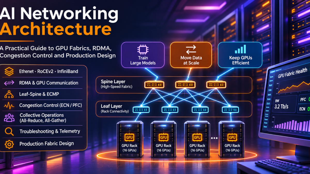
AI Networking Architecture Explained: Ethernet, InfiniBand, RoCEv2, and RDMA
Understanding the high-performance networking technologies that connect GPU clusters, accelerate distributed AI workloads, and support modern AI infrastructure.
Artificial intelligence is transforming data centre network architecture. Large-scale model training and demanding inference workloads require enormous volumes of data to move between GPUs, servers, storage systems, and distributed computing resources.
Traditional enterprise networks are primarily designed around application connectivity, service availability, and general-purpose traffic forwarding. High-performance AI networks must additionally support intensive east-west communication, high throughput, predictable latency, and efficient accelerator-to-accelerator data exchange.
Technologies such as Ethernet, InfiniBand, Remote Direct Memory Access (RDMA), and RDMA over Converged Ethernet version 2 (RoCEv2) play important roles in these architectures. Understanding how they interact with GPU communication patterns, congestion control, and network fabric topology is essential for engineers designing modern AI systems.
GPU Compute Cluster
Distributed accelerators generate intensive communication workloads during AI training and inference.
High-Performance Network
Ethernet or InfiniBand fabrics provide high-bandwidth connectivity between compute nodes.
Efficient Data Exchange
RDMA-capable communication can reduce CPU involvement and data movement overhead.
Simplified conceptual relationship. RDMA is a communication mechanism used over supported network transports, not a separate physical destination in the packet-forwarding path.
High-Bandwidth GPU Communication
Distributed training generates large volumes of traffic between accelerators and requires efficient network utilization.
Latency and Congestion Engineering
Queueing, congestion, packet loss, and communication imbalance can reduce the efficiency of synchronized AI workloads.
Scalable AI Network Fabrics
Leaf-spine architectures, high-speed links, topology planning, and appropriate traffic engineering support cluster growth.
AI Performance Depends on More Than GPU Compute
A powerful GPU cluster can still perform poorly when its network cannot sustain the communication patterns required by distributed workloads. The goal of AI network engineering is to combine efficient data movement, high-performance switching, congestion management, and scalable fabric architecture so that network limitations do not unnecessarily constrain accelerator performance.
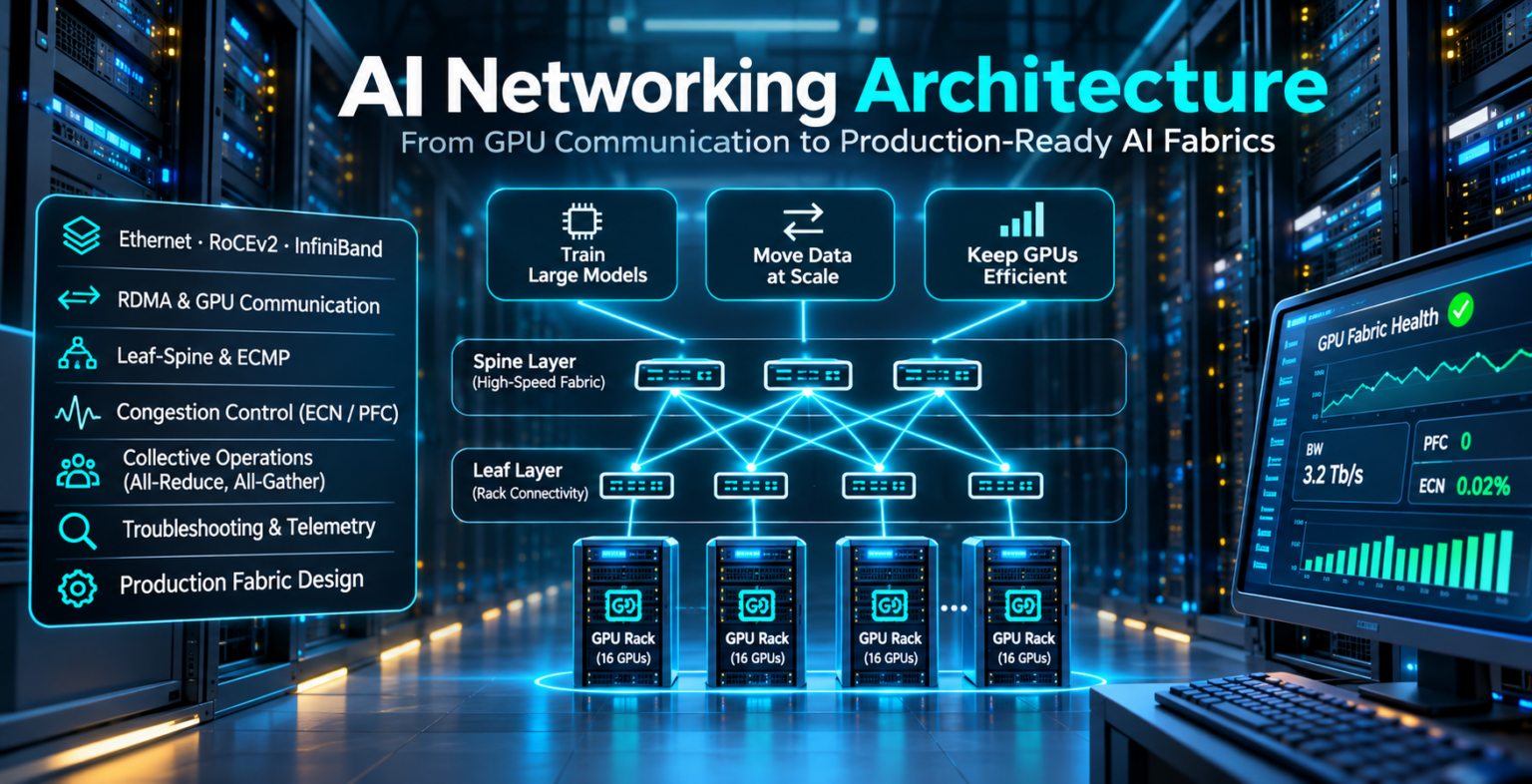
Explore the AI Network Fabric
Follow the engineering journey from GPU communication fundamentals to production AI fabric architecture. Select any node to jump directly to its section.
Understanding AI Networking Architecture
AI networking connects accelerators, compute nodes, storage systems, and distributed workloads through high-performance communication fabrics. Unlike conventional application networks, large-scale AI training environments are especially sensitive to bandwidth, congestion, communication synchronization, and network topology.
Modern AI infrastructure is built around large collections of accelerators working together on computationally intensive tasks.
During distributed training, GPUs exchange model parameters, gradients, activations, and other intermediate data. These exchanges can create sustained, high-volume communication across the network fabric.
The network therefore becomes an important part of the overall computing system, rather than simply a transport mechanism connecting independent servers.
1.1 Why AI Workloads Change Network Requirements
Conventional enterprise networks support a broad range of application traffic, including user requests, database queries, storage access, and service-to-service communication.
Distributed AI workloads introduce additional requirements because many accelerators may need to exchange data within tightly synchronized computation phases.
If some GPUs complete their communication later than others, synchronized training operations can be delayed while slower participants finish.
High Aggregate Bandwidth
Large GPU clusters require substantial aggregate network capacity to exchange training data efficiently.
Predictable Communication
Tail latency, congestion, and retransmission overhead can slow collective operations involving many accelerators.
Scalable Network Fabrics
High-performance switching topologies support increasing numbers of GPUs without introducing unnecessary bottlenecks.
1.2 The Three Networking Domains of an AI Cluster
Large AI environments commonly distinguish between front-end, back-end, and storage connectivity.
These are logical network roles and do not always require three completely separate physical fabrics.
Front-End Network
Provides application access, cluster management, orchestration, APIs, and connections to external services.
Back-End Network
Carries high-performance accelerator communication for distributed training and other tightly coupled compute workloads.
Storage Network
Connects compute systems to datasets, checkpoints, and shared storage. It may be dedicated or share infrastructure.
1.3 AI Cluster Architecture: From Compute to Fabric
The following conceptual architecture illustrates how a distributed GPU cluster connects to a high-performance network.
In real deployments, GPU servers connect through network interface adapters and switches, with multiple links and potentially multiple switching tiers.
AI Training and Orchestration Layer
Distributed training framework, job scheduling, and workload coordination
High-Performance Back-End Fabric
Ethernet with RoCEv2 or InfiniBand, using suitable network adapters, switches, and traffic management
Compute Node 1
Accelerator resources
Compute Node 2
Accelerator resources
Compute Node 3
Accelerator resources
Compute Node 4
Accelerator resources
Conceptual architecture only. The diagram illustrates logical workload coordination and network connectivity rather than a literal packet path through the orchestration layer.
1.4 Traditional Data Centre Networking vs AI Networking
AI fabrics build on familiar data centre networking principles, but their performance objectives and traffic characteristics can be substantially different.
| Engineering Area | Traditional Data Centre | High-Performance AI Fabric |
|---|---|---|
| Primary Objective | Application connectivity and service availability | Efficient distributed accelerator communication |
| Traffic Patterns | Mixed north-south and east-west application traffic | Often intensive east-west traffic with collective communication |
| Performance Focus | Availability, throughput, latency, and general application SLAs | High throughput, low tail latency, and synchronized workload efficiency |
| Transport | Typically TCP/IP and conventional Ethernet | Ethernet/RoCEv2, InfiniBand, or other workload-appropriate transports |
| Congestion | Standard queueing, QoS, and transport congestion control | Careful buffer, ECN, PFC where applicable, and end-to-end congestion design |
| Scaling | Application and network capacity expansion | Compute scale-out with attention to fabric bandwidth and communication locality |
| Operational Metrics | Interface errors, utilization, reachability, and application performance | Those metrics plus congestion, RDMA behavior, collective latency, and GPU idle time |
1.5 How a Distributed Training Communication Cycle Works
Distributed training involves repeated computation and communication phases.
The precise sequence depends on the training framework and parallelism strategy, but a simplified data-parallel example illustrates the relationship.
Local Computation
Each GPU processes its assigned data and calculates local gradients.
Collective Communication
GPUs exchange and aggregate gradients through operations such as AllReduce.
Model Update
The training process uses the aggregated information to update model parameters.
Next Iteration
The process repeats. Communication delays can increase overall training time.
1.6 Why Network Congestion Matters to GPU Utilization
GPUs deliver the greatest benefit when computation resources remain productively occupied.
Network congestion can delay communication phases, increase collective operation completion times, and cause accelerators to wait for dependent work.
These effects become especially important when a large number of GPUs must participate in synchronized operations.
1.7 Engineering Checklist: Understanding the AI Fabric
The Network Is Part of the AI Computing System
In distributed AI infrastructure, network performance directly influences communication efficiency and overall workload completion time. A well-designed AI fabric combines high bandwidth, predictable communication, scalable topology, and effective congestion management to support the computing capabilities of modern GPU clusters.
AI Network Architecture Explorer
Discover the infrastructure behind GPU clusters. Explore traffic separation, switching layers, storage access and cluster management through an interactive architecture.
02 / Network plane inspector
Select a component in the topology to inspect its engineering role.
03 / Traffic journey inspector
Select a network plane to begin.
cluster:~$

Awaiting traffic journey.
Modern AI infrastructure commonly separates user/application traffic, accelerator communication, storage I/O and cluster management into distinct logical or physical network planes. The exact separation depends on cluster scale, performance, security and operational requirements.
AI Workloads and GPU Communication Patterns
Distributed AI workloads divide computation across multiple GPUs and servers. The chosen parallelism strategy determines how accelerators exchange data, how often synchronization occurs, and which network performance characteristics matter most.
A single GPU can execute many AI workloads, but large models and demanding training jobs often require multiple accelerators operating together.
Distributed training frameworks divide model computation, training data, or execution stages across available GPU resources.
Each approach creates different communication requirements that influence network bandwidth, latency, topology, and congestion behavior.
2.1 Data Parallelism
Data parallelism distributes different portions of a training dataset across multiple workers, each maintaining the model state required for its computation.
During training, workers calculate local gradients and exchange information to keep model updates consistent.
Collective operations such as AllReduce are commonly used to aggregate gradients across participating accelerators.
2.2 Tensor Parallelism
Tensor parallelism partitions individual model operations or tensors across multiple accelerators.
Because computation is divided within model layers, GPUs may need frequent communication during forward and backward passes.
These exchanges can be sensitive to network latency and available bandwidth, particularly when tensor-parallel groups span multiple servers.
2.3 Pipeline Parallelism
Pipeline parallelism divides model layers into stages assigned to different devices or groups of devices.
Intermediate activations are passed between stages during forward execution, while backward computation exchanges gradient information between corresponding stages.
Pipeline efficiency depends on stage balance, communication delays, microbatch scheduling, and pipeline bubbles.
Data Parallelism
Replicates model computation across workers and synchronizes gradients or related training state.
Tensor Parallelism
Splits tensor operations across accelerators, often requiring frequent communication within layers.
Pipeline Parallelism
Splits model execution into stages and exchanges activations and gradients between stages.
2.4 GPU Communication Across the Network Fabric
The following simplified diagram illustrates a group of GPUs participating in distributed communication.
Actual communication algorithms may use rings, trees, hierarchical groups, or other topologies to coordinate data exchange.
Worker 0
Local computation
Worker 1
Local computation
Worker 2
Local computation
Worker 3
Local computation
Animated particles represent logical data exchange. The diagram does not prescribe a specific collective algorithm or physical packet path.
2.5 Understanding Collective Communication Operations
Collective communication coordinates data exchange among multiple participating processes or accelerators.
These operations are central to many distributed AI training and inference architectures.
Aggregate and Distribute
Combines values across participating workers using a reduction operation, then makes the reduced result available to all.
Collect Distributed Data
Gathers different data portions from participating workers so that each receives the combined collection.
Reduce and Partition
Reduces data across workers and distributes separate portions of the result to participants.
2.6 Communication Patterns and Network Requirements
| Workload Pattern | Typical Communication | Network Consideration |
|---|---|---|
| Data Parallelism | Gradient aggregation and synchronization | Aggregate bandwidth and collective completion time |
| Tensor Parallelism | Frequent intra-layer data exchange | Latency, bandwidth, and communication locality |
| Pipeline Parallelism | Activations and gradients between stages | Stage placement, latency, and balanced throughput |
| AllReduce | Reduction and distribution among workers | Collective algorithm efficiency and congestion |
| AllGather | Exchange of distributed data partitions | Bandwidth and communication scheduling |
| ReduceScatter | Reduction followed by distributed result partitions | Efficient data movement and network utilization |
2.7 Why GPU Communication Locality Matters
Communication within a server can use high-speed local interconnects, while communication between servers typically traverses network adapters and switching infrastructure.
Placement decisions therefore affect how much traffic crosses the network fabric.
Communication-intensive groups may benefit from placement strategies that reduce unnecessary cross-server or cross-fabric traffic, subject to available hardware and scheduling constraints.
2.8 Engineering Example: Distributed Training Across Multiple Servers
Eight GPUs Across Two Compute Servers
Consider a training environment containing two servers with four GPUs each. The training framework distributes computation across all eight accelerators.
If the workload uses data parallelism, workers must periodically aggregate gradients. If tensor-parallel groups span the two servers, additional communication may occur within model execution.
The network engineer should determine which exchanges remain within each server, which cross the network fabric, and whether congestion or limited bandwidth delays synchronized computation.
2.9 Engineering Checklist: GPU Communication Analysis
AI Network Requirements Begin with Communication Patterns
Distributed AI workloads create different network demands depending on how computation is partitioned and synchronized. Understanding data parallelism, tensor parallelism, pipeline parallelism, and collective communication is essential before selecting network transports, designing fabrics, or optimizing congestion behavior.
GPU Traffic Pattern Visualiser
Explore how distributed AI workloads create different communication patterns across GPU clusters. Compare data, tensor, pipeline and expert parallelism.
01 / GPU communication topology
Data Parallelism02 / Workload parameters
03 / Communication trace
Select Animate GPU communication.
gpu-cluster:~$

Awaiting workload simulation.
Different parallelism strategies place different demands on the GPU interconnect.
Distributed training performance depends on more than raw network bandwidth. GPU communication frequency, payload size, synchronisation, network latency and collective algorithms can all influence application throughput and scaling efficiency.
Ethernet vs InfiniBand for AI Networks
Ethernet and InfiniBand are two major networking technologies used to connect distributed AI compute systems. Both can support high-throughput, low-latency communication, but they differ in their protocol architecture, operational ecosystem, congestion mechanisms, and deployment models.
Choosing a network technology for an AI cluster requires more than comparing nominal port speeds.
Engineers must consider accelerator communication patterns, RDMA support, network topology, congestion behavior, operational tooling, and the broader infrastructure ecosystem.
3.1 Ethernet Architecture for AI Infrastructure
Ethernet is the dominant networking technology across enterprise and cloud data centres. Its mature ecosystem includes standardized switching, IP routing, automation platforms, and monitoring tools.
AI clusters can use high-speed Ethernet interfaces with RoCEv2-capable adapters to support RDMA communication across routed IP networks.
However, achieving reliable high-performance RDMA behavior requires careful engineering of congestion control, traffic classification, buffering, and packet-loss handling.
3.2 InfiniBand Architecture for AI Infrastructure
InfiniBand is a high-performance interconnect architecture widely associated with supercomputing, high-performance computing, and large AI clusters.
It provides native RDMA capabilities and uses its own link, transport, addressing, and fabric-management mechanisms.
InfiniBand fabrics typically use subnet management to discover devices, configure connectivity, and establish forwarding information.
Features such as credit-based link-level flow control and adaptive routing in supported implementations can contribute to efficient communication, although congestion and performance tuning remain important.
3.3 Conceptual Ethernet and InfiniBand Fabric Comparison
Simplified logical architectures. Real deployments use host adapters, multiple switching tiers, and workload-specific connectivity.
3.4 Ethernet vs InfiniBand: Engineering Comparison
| Engineering Area | Ethernet with RoCEv2 | InfiniBand |
|---|---|---|
| Network Architecture | Ethernet and IP networking | Dedicated InfiniBand protocol architecture |
| RDMA | Supported through RoCE-capable hardware and software | Native RDMA support |
| Routing | Standard IP routing and Ethernet switching | InfiniBand fabric forwarding managed through subnet-management mechanisms |
| Congestion Management | ECN, endpoint congestion control, QoS, and PFC where appropriate | Credit-based link flow control and supported fabric congestion mechanisms |
| Operational Ecosystem | Broad enterprise and cloud networking ecosystem | Specialized HPC and AI fabric ecosystem |
| Interoperability | Broad multi-vendor Ethernet standards, subject to RoCE interoperability testing | Standards-based InfiniBand with a more specialized vendor ecosystem |
| Deployment Complexity | Requires careful end-to-end RDMA and congestion engineering | Requires InfiniBand-specific fabric administration and expertise |
| Typical Use Cases | Enterprise AI, cloud AI, and large-scale AI clusters | HPC and high-performance AI training clusters |
3.5 RDMA: The Common Communication Capability
Remote Direct Memory Access enables compatible systems to transfer data between registered memory regions with reduced CPU involvement compared with conventional socket-based data movement.
RDMA is not exclusive to InfiniBand. Ethernet environments can also support RDMA using RoCE, while other RDMA technologies exist for different transports.
The important distinction is between the RDMA programming and communication model and the underlying network transport used to carry RDMA operations.
3.6 Congestion and Flow Control Differences
High-performance AI communication can produce intense traffic bursts and periods of sustained network utilization.
Ethernet RoCEv2 deployments commonly use ECN-based congestion signaling and compatible endpoint rate control.
Priority Flow Control may be deployed for selected traffic classes, but excessive pause propagation and head-of-line blocking can introduce operational risks.
InfiniBand uses credit-based link-level flow control, alongside additional congestion-management features in supported implementations.
3.7 Selecting the Right Technology
When Ethernet May Be Appropriate
Ethernet may be attractive when an organization values IP integration, broad switching options, existing network expertise, automation compatibility, and a common infrastructure ecosystem. RoCEv2 performance must still be validated for the intended AI workloads.
When InfiniBand May Be Appropriate
InfiniBand may be attractive for specialized AI and HPC clusters where native RDMA, integrated fabric management, and a mature high-performance interconnect ecosystem align with the compute platform and operational requirements.
3.8 Practical Engineering Scenario
Consider an organization deploying a distributed training environment with hundreds of GPUs.
The design team must evaluate the required collective communication performance, expected traffic patterns, network capacity, operational model, and expansion plans.
Rather than selecting a technology based solely on advertised bandwidth or latency, engineers should benchmark representative workloads, measure communication completion times, and investigate congestion behavior under realistic load.
3.9 Engineering Checklist: Fabric Technology Selection
Fabric Selection Is an End-to-End Engineering Decision
Ethernet with RoCEv2 and InfiniBand can both support demanding AI communication workloads. The correct choice depends on application behavior, RDMA performance, congestion management, hardware integration, operational capabilities, and measured scalability rather than any single specification.
AI Fabric Technology Comparator
Compare Ethernet/TCP, Ethernet with RoCEv2, and InfiniBand for GPU clusters. Configure engineering requirements and evaluate the architectural trade-offs.
01 / AI workload requirements
02 / Engineering recommendation
The lab compares technology characteristics against the selected workload requirements. Scores are illustrative and not benchmark results.
| Engineering dimension | Ethernet / TCP | Ethernet / RoCEv2 | InfiniBand |
|---|---|---|---|
| Transport | TCP/IP | RDMA over UDP/IP/Ethernet | Native InfiniBand transport |
| RDMA capability | Not native to TCP | Yes | Yes |
| Network ecosystem | Broad Ethernet/IP | Ethernet/IP with RDMA configuration | Specialised InfiniBand |
| Congestion management | TCP congestion control | ECN, DCQCN and optional PFC | Fabric-specific mechanisms |
| Typical use | Applications, management, general services | Distributed AI/HPC | Distributed AI/HPC |
Ethernet and InfiniBand are not simply fast-versus-slow alternatives. Both can support high-performance AI fabrics. RoCEv2 brings RDMA to Ethernet/IP networks, while InfiniBand provides an integrated high-performance fabric. Actual performance depends on hardware, software, topology, congestion control and workload characteristics.
RDMA and RoCEv2 Architecture
Remote Direct Memory Access (RDMA) provides a communication model for transferring data between registered memory regions with reduced CPU involvement. RoCEv2 extends RDMA communication across routable Ethernet/IP networks, making it an important technology for high-performance distributed AI infrastructure.
Conventional network applications frequently use socket interfaces and operating-system networking stacks to exchange data. RDMA provides a different programming model in which applications submit operations to capable network adapters.
Once resources are configured, supported RDMA operations can move data directly between registered memory regions, avoiding repeated CPU-driven copying through conventional socket buffers. This can improve communication efficiency for demanding AI and HPC workloads.
4.1 RDMA Communication Fundamentals
RDMA communication uses network adapters, registered memory, work queues, completion mechanisms, and transport-specific connection or addressing resources.
An application typically registers memory for RDMA access, creates a queue pair, configures communication with a peer, and posts work requests describing operations to perform.
Memory Registration
Makes selected memory accessible to the RDMA adapter with appropriate access permissions and registration keys.
Queue Pairs
Provide send and receive work queues. The transport type determines how communication and reliability operate.
Completion Queues
Report completion events for work requests, allowing software to determine operation progress and detect relevant errors.
4.2 RDMA Endpoint Architecture
The following conceptual architecture shows two compute nodes exchanging data through RDMA-capable network adapters.
Logical communication architecture. The adapters exchange RoCEv2 packets through the network; CPU involvement varies by operation and implementation.
4.3 RDMA Operations: SEND, WRITE, and READ
RDMA supports several communication operations with different application responsibilities and data movement semantics.
| Operation | Behavior | Engineering Consideration |
|---|---|---|
| SEND / RECEIVE | Sends a message to a peer that has appropriate receive resources available. | Receiver participation and receive-queue management matter. |
| RDMA WRITE | Writes data into an authorized remote memory region. | Requires suitable remote address and access key information. |
| RDMA READ | Retrieves data from an authorized remote memory region. | Requires remote read permissions and suitable transport resources. |
| Atomic Operations | Perform supported atomic operations against remote memory. | Availability and supported sizes depend on the adapter and transport capabilities. |
4.4 RoCEv2 Packet Encapsulation
RoCEv2 carries RDMA transport information over UDP/IP. This enables communication across compatible Layer 3 Ethernet networks.
A typical IPv4 RoCEv2 frame contains an Ethernet header, IP header, UDP header, InfiniBand-derived RDMA transport headers, an optional operation payload, and relevant integrity fields.
Simplified, not byte-scaled. RoCEv2 commonly uses UDP destination port 4791. The Base Transport Header (BTH) carries transport information, with additional headers depending on the operation. The RDMA invariant CRC and Ethernet FCS protect different portions of the frame; the Ethernet FCS is not part of the UDP payload.
4.5 Queue Pairs and Reliable Communication
Queue pairs are central RDMA resources. Their state, transport type, and peer configuration determine which operations are available.
Reliable Connected (RC) transport supports reliable, ordered delivery for a connected queue pair and is commonly used in RoCEv2 environments.
The RDMA transport implements reliability mechanisms rather than relying on TCP. The underlying RoCEv2 packet is carried over UDP, but it is incorrect to assume that all RoCEv2 communication is therefore unreliable.
4.6 A RoCEv2 Communication Journey
Prepare Resources
Register memory, configure queue pairs, and establish the required peer communication information.
Post Work Request
The application submits a SEND, RDMA WRITE, or RDMA READ request to the relevant work queue.
Transport Across Fabric
The adapter generates RoCEv2 traffic, which traverses Ethernet switches and IP routers as needed.
Complete Operation
The destination adapter processes the operation and applicable completions are reported to software.
4.7 RoCEv2 Routing and ECMP Considerations
Because RoCEv2 uses IP encapsulation, traffic can traverse routed fabrics. Network devices forward packets using their normal IP forwarding behavior, subject to routing, policy, and supported hardware capabilities.
Equal-Cost Multipath (ECMP) can distribute flows across multiple network paths. However, conventional flow hashing may place a long-lived RDMA flow on one path, even when other links have spare capacity.
Packet reordering, path selection, and load balancing must therefore be evaluated against the selected RDMA transport and NIC behavior.
4.8 RDMA Security and Memory Access
RDMA's ability to access registered memory makes access control and resource isolation especially important.
Applications must manage memory registration permissions, remote access keys, queue pair state, and authorized peer communication. Network segmentation and host-level protections remain relevant.
RoCEv2 does not inherently encrypt application data. Encryption, authentication, and isolation must be addressed separately according to the deployment's security model.
4.9 Troubleshooting RDMA and RoCEv2
RDMA failures may originate in application resource management, NIC configuration, transport state, IP connectivity, or network congestion. Successful ping tests alone do not prove that RDMA communication works.
RoCEv2 Connects RDMA Communication to Routed Ethernet Fabrics
RDMA improves the efficiency of supported data movement operations, while RoCEv2 provides a way to carry RDMA traffic across Ethernet/IP networks. Successful deployment requires correct endpoint resources, transport configuration, network forwarding, congestion engineering, and security controls working together as one system.
RDMA Packet Journey Lab
Trace an RDMA operation from application memory to the receiving host. Inspect queue pairs, memory registration, RoCEv2 encapsulation and completion events.
01 / RDMA communication path
RDMA Write02 / RDMA configuration
03 / RoCEv2 packet inspector
The Base Transport Header (BTH) carries transport information such as the opcode and destination queue-pair number.
rdma:~$

Awaiting RDMA operation.
RDMA enables network adapters to transfer data directly to or from registered memory with reduced CPU involvement in the data path. Reliable Connected queue pairs, memory permissions, work requests and completion queues are important parts of the programming model. RoCEv2 transports RDMA packets over UDP/IP/Ethernet.
AI Leaf-Spine Fabric Design
AI clusters require network fabrics capable of connecting large numbers of accelerators while delivering high aggregate bandwidth, predictable communication, resilient paths, and scalable connectivity. Leaf-spine architectures provide a common foundation for Ethernet-based AI network design.
The leaf-spine architecture, based on Clos network principles, connects compute-facing leaf switches to a shared tier of spine switches.
Each leaf typically connects to multiple spines, creating multiple equal-cost paths between endpoints attached to different leaves.
This architecture supports horizontal growth and can reduce dependence on a small number of high-capacity aggregation devices.
5.1 Understanding the AI Leaf-Spine Topology
The following simplified architecture shows four spine switches, four leaf switches, and GPU compute servers connected to the leaf tier.
Illustrative two-tier Clos fabric. Each leaf has a link to every spine. Actual AI fabrics may contain many more servers, links, and switching tiers. Animated particles represent possible inter-leaf paths, not real packet traces.
5.2 Leaf Switches and GPU Server Connectivity
Leaf switches provide network attachment for GPU servers and other cluster infrastructure.
High-performance compute nodes may contain multiple network adapters, each connected to a separate network port or fabric rail.
The server connectivity model influences fault isolation, traffic distribution, cable requirements, and total available network bandwidth.
Compute Connectivity
GPU servers connect through high-speed network adapters. Adapter count and port speed influence per-node capacity.
Multiple Fabric Paths
Equal-cost routes across spine switches can provide path diversity and aggregate fabric capacity.
Horizontal Expansion
Additional leaf capacity and planned spine expansion support growth within the fabric's design limits.
5.3 ECMP and Traffic Distribution
In routed Ethernet leaf-spine fabrics, Equal-Cost Multipath allows switches to install multiple next hops for destinations reachable through equal-cost paths.
Traditional ECMP commonly uses flow hashing to select a path for each flow. This preserves packet ordering within a flow but does not guarantee even utilization across all links.
AI traffic can contain long-lived, high-bandwidth flows, so hash collisions and traffic imbalance may create localized congestion.
5.4 Understanding Fabric Oversubscription
Oversubscription compares the aggregate bandwidth of downstream-facing ports with the aggregate upstream bandwidth available from a switch.
A non-oversubscribed leaf design provides upstream capacity equal to its total downstream port capacity, assuming equivalent full-duplex bandwidth accounting.
Example: 32 GPU-facing Ports at 400 Gb/s
Consider a leaf switch with 32 server-facing ports operating at 400 Gb/s.
To achieve a nominal 1:1 downlink-to-uplink capacity ratio, the leaf would require 12.8 Tb/s of aggregate spine-facing bandwidth.
If the leaf instead provides 6.4 Tb/s of uplink bandwidth, the nominal ratio becomes 2:1.
These are theoretical port-capacity calculations. Effective application throughput also depends on protocol overhead, packet sizes, traffic distribution, congestion, and device capabilities.
5.5 Rail-Optimized AI Network Architecture
Some large GPU clusters use rail-optimized network designs.
In these architectures, corresponding network adapters across compute servers may connect to separate logical or physical network rails.
Rail organization can help align communication patterns with network topology, distribute traffic, and isolate certain failures or congestion domains.
The precise topology varies by accelerator platform, network technology, and deployment architecture.
5.6 AI Fabric Routing and Control Plane
Ethernet AI fabrics may use routing protocols such as BGP to distribute network reachability across leaf and spine devices.
Routed underlays can provide multiple equal-cost paths and avoid extending large Layer 2 domains throughout the compute fabric.
However, the routing control plane and the RDMA data plane solve different problems. Correct routing alone does not guarantee suitable RoCEv2 performance.
5.7 Fabric Design Trade-Offs
| Design Area | Engineering Decision | Potential Trade-Off |
|---|---|---|
| Spine Count | Number of available equal-cost fabric paths | Capacity and resilience versus hardware and cabling cost |
| Link Speed | Bandwidth of server and fabric connections | Throughput versus optics, cabling, and platform capability |
| Oversubscription | Downlink-to-uplink bandwidth ratio | Infrastructure efficiency versus congestion risk |
| Rail Design | Mapping network adapters to fabric domains | Traffic locality and isolation versus complexity |
| Routing | ECMP, underlay design, and failure convergence | Path diversity versus operational complexity |
| Congestion Control | Queue management, ECN, and PFC where appropriate | Performance versus pause propagation and queueing behavior |
5.8 Four Stages of AI Fabric Design
Characterize Workloads
Identify GPU count, communication patterns, bandwidth requirements, and performance targets.
Size the Fabric
Determine adapter, leaf, spine, and uplink capacity with realistic traffic assumptions.
Engineer Resilience
Plan routing, failure domains, path diversity, and operational recovery behavior.
Validate Performance
Benchmark representative GPU communication, inspect congestion, and test failure scenarios.
5.9 Production AI Fabric Design Checklist
AI Fabric Design Connects Network Topology to GPU Performance
A well-designed AI leaf-spine fabric provides scalable connectivity between compute nodes while minimizing avoidable communication bottlenecks. Engineers must consider server connectivity, ECMP, aggregate bandwidth, oversubscription, rail topology, and congestion behavior as parts of one end-to-end architecture.
GPU Cluster Fabric Builder
Build a multi-rack AI leaf-spine network. Explore fabric capacity, ECMP path diversity, oversubscription and the impact of link failures.
01 / Fabric design controls
02 / Interactive leaf-spine topology
fabric:~$

Awaiting fabric construction.
A leaf-spine fabric provides predictable hop counts and multiple equal-cost paths between racks. However, the existence of multiple ECMP paths does not guarantee that individual flows are evenly distributed. Capacity planning must consider actual GPU NIC bandwidth, switch port counts, topology, traffic patterns and failure scenarios.
PFC, ECN, Congestion Control, and Lossless Networking
High-performance AI networks must manage bursts, sustained traffic, and competing RDMA flows without allowing congestion to become a major GPU performance bottleneck. Priority Flow Control, Explicit Congestion Notification, endpoint rate control, and queue management all contribute to the behavior of Ethernet-based AI fabrics.
Distributed AI training can generate large volumes of simultaneous network traffic. Collective communication operations may cause many accelerators to transmit data during closely aligned time windows.
When incoming traffic exceeds the rate at which a switch can transmit packets, data accumulates in output queues.
Persistent congestion increases queueing delay, while exhausted buffers can cause packet drops and transport recovery overhead.
6.1 Understanding Congestion in AI Ethernet Fabrics
Congestion occurs when traffic offered to a network resource exceeds its available service capacity.
Common causes include oversubscribed links, synchronized traffic bursts, ECMP imbalance, and many-to-one communication patterns.
RoCEv2 traffic can be especially sensitive to congestion because transport recovery and completion delays can affect synchronized AI workloads.
Queue Buildup
Traffic arrives faster than it can depart, increasing buffer occupancy and queueing delay.
Pause Propagation
Link-level priority pauses can protect buffers but may affect upstream traffic sharing the paused priority.
Rate Adaptation
Congestion marking can signal compatible endpoints to reduce sending rates before severe congestion develops.
6.2 Animated Congestion-Control Architecture
The following diagram illustrates a sender, a congested switch, and a receiving endpoint.
RDMA Sender
Generates RoCEv2 traffic toward the destination.
Congested Switch
Queue occupancy rises under load.
RDMA Receiver
Receives traffic and may generate congestion feedback.
Conceptual illustration. Animated particles represent traffic movement, not measured packet timing or actual congestion thresholds.
6.3 Priority Flow Control (PFC)
Priority Flow Control, defined by IEEE 802.1Qbb, extends Ethernet flow control by allowing selected traffic priorities to be paused independently.
When a switch detects buffer pressure for a configured priority, it can transmit a PFC pause frame to the directly connected upstream device.
The upstream device temporarily stops transmitting frames for that priority on the affected link, while other priorities may continue.
PFC can help prevent drops caused by buffer exhaustion, but it also introduces operational risks.
6.4 Explicit Congestion Notification (ECN)
ECN provides a mechanism for network devices to indicate congestion without necessarily dropping packets.
When congestion marking is enabled, a switch may mark ECN-capable IP packets according to its configured queue-management policy.
The receiving transport must interpret or relay the congestion information so that the sender can react.
In RoCEv2 environments, ECN is commonly integrated with compatible endpoint congestion-control algorithms.
6.5 DCQCN: Data Center Quantized Congestion Notification
DCQCN is a congestion-control approach used in supported RoCEv2 environments.
It combines ECN marking, receiver-generated congestion notification packets, and sender-side rate adjustment.
The objective is to respond to congestion while maintaining useful network throughput.
Queue Pressure
Traffic builds up in a switch queue.
ECN Marking
The switch marks eligible packets to indicate congestion.
Congestion Notification
The receiving endpoint generates feedback for the sender.
Rate Adjustment
The sender adjusts its transmission rate according to the algorithm.
6.6 PFC vs ECN vs DCQCN
| Mechanism | Primary Function | Scope | Engineering Risk |
|---|---|---|---|
| PFC | Temporarily pauses selected Ethernet priorities | Directly connected Ethernet link | Pause propagation and head-of-line blocking |
| ECN | Marks eligible IP packets to indicate congestion | Network signaling to compatible transport endpoints | Incorrect thresholds or unsupported endpoint response |
| DCQCN | Uses congestion feedback to regulate RoCEv2 sender rate | End-to-end RDMA congestion-control behavior | Rate-control instability or poor tuning |
| Buffer Management | Absorbs bursts and allocates queue capacity | Switch queues and shared buffer resources | Buffer exhaustion and excessive queueing |
6.7 What Does Lossless Ethernet Actually Mean?
The phrase "lossless Ethernet" is often used to describe configurations intended to avoid congestion-related packet drops for selected traffic classes.
It does not mean that every packet is guaranteed to arrive under every possible failure condition.
Physical errors, configuration problems, equipment faults, and severe congestion events can still cause packet loss or communication failures.
Some modern RoCE implementations can tolerate packet loss more effectively than earlier designs. The appropriate PFC strategy depends on the adapter, transport, and fabric capabilities.
6.8 Common AI Fabric Congestion Failures
| Failure Pattern | Possible Cause | Investigation |
|---|---|---|
| High Queue Occupancy | Oversubscription or synchronized traffic bursts | Inspect per-queue utilization and traffic patterns |
| Excessive PFC | Persistent congestion or incorrect thresholds | Review PFC counters, pause duration, and upstream effects |
| RoCEv2 Throughput Collapse | Packet loss, transport recovery, or congestion-control issues | Correlate RDMA counters, drops, ECN, and sender rates |
| ECMP Hotspot | Uneven flow hashing across available paths | Compare link utilization and flow distribution |
| High Collective Latency | Congestion or communication imbalance | Correlate GPU collective timing with fabric telemetry |
6.9 Production Congestion Engineering Checklist
Congestion Control Is Essential to Efficient AI Fabrics
High-performance AI Ethernet networks depend on coordinated queue management, ECN signaling, endpoint rate control, and carefully designed PFC behavior where required. The goal is to sustain accelerator communication while avoiding excessive queueing, packet recovery overhead, and network-wide pause propagation.
AI Congestion Control Simulator
Explore switch-buffer pressure, ECN marking, Priority Flow Control and sender-rate adaptation in a simplified RoCEv2 network.
01 / Congestion parameters
02 / Switch-buffer visualisation
fabric:~$

Awaiting congestion simulation.
ECN provides congestion feedback before severe buffer pressure develops. A compatible RoCEv2 congestion-control mechanism can reduce sender rates in response to feedback. PFC pauses traffic at a configured priority to reduce loss under pressure, but excessive PFC can cause head-of-line blocking and congestion spreading. Thresholds must be engineered together rather than independently.
Distributed AI Training and Collective Communication
Distributed AI training depends on communication algorithms that coordinate data exchange among multiple accelerators. Collective operations such as AllReduce, AllGather, and ReduceScatter can use ring, tree, or hierarchical strategies. Their performance depends on message size, network bandwidth, latency, topology, and the placement of participating GPUs.
Distributed training divides computation across multiple GPUs and servers. To maintain consistent model execution, participating processes must exchange intermediate data at specific points in the training workflow.
The communication library and training framework coordinate these exchanges through collective operations.
Efficient collective communication is essential because delayed data exchange can prevent dependent computation from proceeding.
7.1 Understanding Collective Communication
Collective communication describes operations involving a group of participating processes or devices.
Unlike a simple point-to-point exchange, a collective operation coordinates data movement across multiple participants.
Common operations include AllReduce, AllGather, ReduceScatter, Broadcast, and Reduce.
AllReduce
Combines values across participating workers and distributes the reduced result to all participants.
AllGather
Collects distributed data portions so that every participant receives the combined data.
ReduceScatter
Reduces distributed values and distributes different portions of the result among participants.
7.2 NCCL and GPU Collective Communication
NVIDIA Collective Communications Library (NCCL) provides communication primitives commonly used by distributed GPU workloads.
NCCL supports collective operations and point-to-point communication across compatible GPU environments.
Depending on the system configuration, communication may use local accelerator interconnects, shared-memory paths, or network adapters for inter-node data exchange.
NCCL can select different communication algorithms and protocols based on operation type, message size, topology, and supported hardware.
7.3 Ring vs Tree Communication Algorithms
Ring and tree algorithms provide different strategies for organizing communication among participating workers.
A ring arranges participants in a logical cycle. Data is exchanged between neighboring participants over multiple steps.
Tree algorithms organize communication into hierarchical relationships, often using reduction and distribution phases.
Logical communication structures, not physical switch topologies. Real collective libraries may use multiple rings, multiple trees, hierarchical algorithms, and topology-specific optimizations.
7.4 Ring AllReduce: ReduceScatter and AllGather
A common ring AllReduce implementation combines two communication phases.
During ReduceScatter, participants exchange and reduce portions of the input data until each owns a portion of the final reduced result.
During AllGather, participants exchange those reduced portions so that every participant receives the complete reduced result.
This approach can make efficient use of available bandwidth for sufficiently large messages, although performance depends on implementation and network conditions.
7.5 Worked Example: Ring AllReduce Traffic
Eight GPUs, 1 GiB Input per GPU
Consider a standard ring AllReduce involving eight GPUs, where each GPU begins with a 1 GiB input buffer.
For the conventional ring algorithm, each participant sends approximately the following amount of data across the complete ReduceScatter and AllGather operation:
Each GPU therefore sends approximately 1.75 GiB during the collective, excluding protocol overhead and implementation-specific additional traffic.
The same expression applies to the approximate received data volume per participant for this algorithm.
This is a communication-volume calculation, not a prediction of elapsed time. Actual completion time depends on bandwidth, latency, topology, and contention.
7.6 Ring vs Tree: Engineering Trade-Offs
| Area | Ring | Tree |
|---|---|---|
| Communication Structure | Logical cyclic exchange between participants | Hierarchical exchange between tree levels |
| Large Messages | Can provide efficient bandwidth utilization | Performance depends on tree algorithm and topology |
| Small Messages | Multiple communication steps can increase latency overhead | Some tree algorithms offer favorable latency scaling |
| Topology Sensitivity | Ring ordering and path placement matter | Tree structure and link utilization matter |
| Scaling Consideration | Step count grows with participant count | Balanced tree depth grows logarithmically |
7.7 Hierarchical Collective Communication
Modern GPU clusters frequently contain multiple levels of connectivity.
GPUs within a server may communicate over local accelerator interconnects, while inter-server communication traverses network adapters and switching fabrics.
Hierarchical communication algorithms can organize collective operations around these topology boundaries.
For example, an implementation may perform local aggregation within nodes, exchange information between nodes, and then distribute results locally.
7.8 Training Iteration and Communication Timing
Training performance depends on both computation and communication.
Some communication can overlap with computation, reducing its visible contribution to iteration time.
Other communication lies on the critical path and must complete before dependent computation continues.
Forward Computation
GPUs execute model operations and exchange required activations.
Backward Computation
Workers calculate gradients and perform communication required by the parallelism strategy.
Collective Exchange
Participating workers aggregate or redistribute data using collective operations.
Iteration Progress
Required communication completes and dependent model execution proceeds.
7.9 Troubleshooting Collective Communication Performance
Slow collective operations can result from network congestion, uneven GPU placement, communication algorithm selection, adapter limitations, or imbalanced computation.
Engineers should correlate collective timing with network telemetry and GPU-level performance data.
| Symptom | Potential Cause | Engineering Investigation |
|---|---|---|
| Slow AllReduce | Congestion, insufficient bandwidth, or algorithm mismatch | Measure collective latency and network utilization |
| GPU Idle Time | Communication wait or workload imbalance | Compare GPU timelines and collective completion times |
| Uneven Performance | Placement, topology, or ECMP imbalance | Inspect process placement and network path utilization |
| Poor Scaling | Communication overhead increasing relative to useful computation | Benchmark across GPU counts and message sizes |
7.10 Engineering Checklist: Collective Communication
Collective Communication Connects Network Performance to Training Efficiency
Distributed training depends on coordinated communication across accelerators. Understanding NCCL, AllReduce, ring and tree algorithms, communication locality, and network topology enables engineers to identify communication bottlenecks and improve AI workload scaling efficiency.
Collective Communication Visualiser
Explore the data movement behind distributed AI training. Animate collective operations and examine communication volume, synchronisation and scaling behaviour.
01 / Collective parameters
02 / GPU communication topology
Select an operation and begin the collective.
collective:~$

Awaiting communication operation.
Collective communication operations are fundamental to distributed AI workloads. Their cost depends on message size, participant count, algorithm, topology, effective bandwidth and latency. Libraries such as NCCL may select different algorithms and protocols according to the hardware and communication characteristics.
AI Network Monitoring and Troubleshooting
Diagnosing AI network performance requires visibility across compute workloads, communication libraries, RDMA adapters, and the underlying switching fabric. Effective troubleshooting connects GPU communication delays to transport counters, congestion signals, routing behavior, and physical network conditions.
AI networking problems do not always appear as complete connectivity failures. A training job may continue running while communication performance deteriorates.
Symptoms can include slower training iterations, increased collective operation latency, uneven GPU utilization, or reduced RDMA throughput.
The challenge is determining whether the underlying cause lies in the application, communication library, network adapter, switching fabric, or their interaction.
8.1 The Four Layers of AI Network Observability
A useful monitoring architecture combines four sources of operational evidence.
Conceptual observability architecture. Actual monitoring systems may use separate collectors, exporters, time-series databases, and tracing platforms.
8.2 GPU and Training Performance Metrics
GPU utilization is useful but should not be interpreted in isolation.
A low-utilization GPU may be waiting for data, communication, synchronization, or another workload dependency.
Engineers should compare GPU activity with training iteration time, collective communication duration, and workload scheduling behavior.
GPU Activity
Identify periods of computation, idle time, and potential communication waits.
Collective Timing
Measure collective completion time, message sizes, and scaling across participants.
Adapter Performance
Inspect RDMA errors, traffic rates, and supported congestion indicators.
8.3 Monitoring RDMA and RoCEv2
RDMA-capable adapters expose operational counters that can help identify transport and network performance issues.
Available counters vary by adapter vendor, firmware, driver, and operating system.
Useful categories include packet transmission, receive errors, transport retries, completion failures, and congestion-related events.
| Metric Category | What It Reveals | Potential Investigation |
|---|---|---|
| RDMA Errors | Transport or adapter-level failures | Inspect queue pair state, link health, and endpoint configuration |
| Retransmissions / Retries | Transport recovery activity where exposed | Investigate packet loss, congestion, and path behavior |
| NIC Throughput | Actual transmit and receive traffic rates | Compare achieved throughput with expected workload demand |
| Completion Errors | Failed RDMA operations | Inspect work completion status and transport configuration |
| Congestion Indicators | ECN or congestion notification activity where supported | Correlate endpoint feedback with switch queue telemetry |
8.4 Monitoring Switch Queues, ECN, and PFC
Switch interface utilization alone is insufficient for diagnosing many AI network incidents.
Short bursts can cause queue pressure even when average interface utilization appears moderate.
Per-queue telemetry, ECN marking, PFC counters, packet drops, and buffer occupancy provide additional evidence.
8.5 Practical Linux and RDMA Investigation Commands
On supported Linux systems, engineers can inspect interfaces, RDMA devices, link statistics, and adapter capabilities using standard utilities.
ip -s link show

rdma link show

ibv_devinfo

ethtool -S <interface>

ethtool -i <interface>

ls /sys/class/infiniband/
8.6 Example Incident: Slow Distributed Training
Training Iteration Time Increases After Cluster Expansion
A distributed training workload expands from 32 GPUs to 64 GPUs. The larger deployment exhibits unexpectedly slow AllReduce completion.
8.7 A Structured AI Network Troubleshooting Method
Define the Symptom
Identify affected jobs, GPUs, operations, time windows, and performance deviations.
Collect Evidence
Gather NCCL, RDMA, NIC, switch queue, and routing telemetry.
Test Hypotheses
Investigate congestion, packet loss, ECMP imbalance, placement, and transport behavior.
Validate Recovery
Compare against a healthy baseline and confirm improvement using representative workloads.
8.8 Building a Healthy AI Fabric Baseline
Effective troubleshooting becomes easier when engineers have previously recorded healthy performance characteristics.
Baselines should include expected collective timing, adapter throughput, interface utilization, queue occupancy, congestion feedback, and error rates.
Baselines must be associated with workload size, GPU count, message size, topology, and relevant software versions.
A baseline from a small cluster cannot automatically be applied to a much larger deployment.
8.9 Production Monitoring Checklist
AI Network Troubleshooting Requires End-to-End Correlation
Reliable diagnosis depends on connecting GPU workload symptoms, collective communication timing, RDMA transport evidence, switch queue telemetry, and routing behavior. Engineers who correlate these layers can distinguish compute bottlenecks from network problems and validate improvements against measurable baselines.
GPU Fabric Incident Investigator
Investigate degraded AI training performance. Examine switch counters, RDMA statistics, congestion telemetry and network path behaviour to identify the root cause.
01 / Network diagnostics
Run diagnostic commands to inspect the simulated network state.
fabric:~$

Select a diagnostic command.
02 / Root-cause investigation
Use the telemetry and CLI output to diagnose the incident.
GPU training slowdowns are not always caused by insufficient bandwidth. PFC storms, uneven ECMP distribution, physical errors and RDMA configuration failures can all affect collective communication. Correlating switch telemetry with GPU and RDMA application metrics is essential for reliable diagnosis.
Designing a Production AI Network Fabric
Production AI networking brings together workload requirements, accelerator connectivity, network transport selection, fabric topology, congestion management, operational security, and end-to-end observability. A successful architecture must support both current training workloads and future cluster growth while remaining measurable, resilient, and operationally manageable.
Designing an AI network requires engineers to coordinate multiple architectural layers rather than treating the switching fabric as an isolated infrastructure component.
GPU communication patterns determine traffic demand. Transport protocols influence reliability and congestion behavior. Network topology determines path availability and aggregate capacity.
Monitoring and operational procedures determine how effectively engineers can detect, diagnose, and recover from failures.
9.1 Define the AI Network Requirements
The first stage is identifying the workloads that the network must support.
Training and inference systems can have different communication characteristics, and even two training workloads may place very different demands on the fabric.
Requirements should include accelerator count, network interface capabilities, communication patterns, expected message sizes, scaling targets, and availability objectives.
Workload Requirements
Identify training and inference workloads, collective communication patterns, and expected scaling behavior.
Network Requirements
Determine bandwidth, latency sensitivity, RDMA capabilities, topology, and congestion-management requirements.
Operational Requirements
Define monitoring, fault isolation, security boundaries, maintenance procedures, and recovery objectives.
9.2 Production AI Network Reference Architecture
Many AI deployments separate network functions into distinct logical or physical connectivity domains.
A back-end compute fabric may carry accelerator-to-accelerator communication, while front-end services and storage connectivity use separate network resources.
This separation can improve traffic isolation, operational clarity, and capacity planning.
Simplified conceptual reference architecture. The two domains may be physically separate or logically isolated, depending on the deployment. Actual designs require appropriate security, routing, resilience, and management connectivity.
9.3 Selecting Ethernet, InfiniBand, and RDMA Transport
The transport decision should reflect workload requirements and the capabilities of the selected compute platform.
Ethernet with RoCEv2 provides an approach for carrying RDMA traffic across IP-based fabrics.
InfiniBand provides a dedicated high-performance interconnect architecture with native RDMA support.
Both technologies can support demanding AI communication, but each requires appropriate engineering expertise and operational tooling.
9.4 Capacity Planning: A 128-GPU Example
Example: 128 GPUs Across 16 Servers
Consider a hypothetical cluster containing 16 servers with eight GPUs per server.
Assume each server has eight dedicated 400 Gb/s network connections to the back-end fabric.
The total nominal server-facing capacity is therefore 51.2 Tb/s in one direction.
For a nominal 1:1 non-oversubscribed design, the aggregate fabric uplink capacity across the relevant leaf switches must be sized accordingly.
This calculation does not imply that every GPU can continuously achieve its nominal port speed for every collective operation. Application throughput depends on communication patterns, protocol overhead, path distribution, and congestion.
9.5 Redundancy and Failure-Domain Design
Production AI fabrics should avoid unnecessary single points of failure.
Redundant paths, multiple spine devices, and appropriate server connectivity can improve resilience.
However, redundancy should be evaluated against workload behavior. A network failure may reduce available bandwidth without completely interrupting IP connectivity.
For synchronized AI workloads, the performance impact of reduced capacity may be significant even when communication remains possible.
| Failure Domain | Potential Impact | Engineering Control |
|---|---|---|
| Network Adapter | Loss or degradation of a compute-node network path | Adapter redundancy where supported and validated |
| Leaf Switch | Loss of connectivity for attached interfaces | Redundant attachment or rail design where appropriate |
| Spine Switch | Reduced aggregate fabric capacity | Multiple spine paths and validated convergence |
| Congestion Domain | Communication delay or throughput degradation | Traffic isolation, congestion control, and capacity planning |
| Management Services | Reduced visibility or operational control | Independent management access and resilient monitoring |
9.6 Security and Network Isolation
AI network infrastructure requires appropriate security boundaries between compute workloads, storage systems, management services, and external access points.
The back-end compute fabric should not automatically be treated as a trusted environment simply because it is dedicated to AI traffic.
Engineers should consider access control, network segmentation, management-plane protection, host security, and RDMA memory access permissions.
Encryption requirements should also be addressed explicitly because RDMA transports do not universally provide end-to-end data encryption.
9.7 Deployment and Validation Phases
Architecture
Define workloads, transport technology, topology, capacity, security, and resilience requirements.
Fabric Deployment
Configure switching, routing, adapter connectivity, traffic classes, and management.
Performance Testing
Validate RDMA, collective communication, congestion behavior, and workload scaling.
Operational Handover
Establish baselines, monitoring, incident procedures, maintenance controls, and recovery testing.
9.8 Production Acceptance Testing
Before production deployment, engineers should validate both functional connectivity and workload-level performance.
Network acceptance testing should include normal operation, congestion conditions, component failures, and recovery scenarios.
| Test Area | Validation Objective | Evidence |
|---|---|---|
| Connectivity | Confirm correct host, adapter, and network reachability | Routing state, link health, RDMA connectivity tests |
| Performance | Measure throughput and latency under representative workloads | RDMA benchmarks and collective communication results |
| Congestion | Validate queue behavior and endpoint rate control | ECN, PFC, drop, queue, and transport counters |
| Resilience | Assess link and switch failure impact | Convergence, recovery, and application performance measurements |
| Operations | Verify monitoring, alerting, and incident procedures | Telemetry dashboards, alerts, and documented runbooks |
9.9 Final Production AI Fabric Checklist
Production AI Networking Is an End-to-End Systems Engineering Discipline
Building a reliable AI fabric requires coordinated decisions across GPU communication, RDMA transport, Ethernet or InfiniBand, network topology, congestion control, security, observability, and operational resilience. The strongest designs are those validated against real workload requirements and supported by measurable engineering evidence.
Production AI Fabric Design Studio
Design and assess a production-style AI networking fabric. Combine transport, bandwidth, topology, resilience, congestion management and operational visibility.
01 / Architecture configuration
02 / Architecture blueprint
03 / Architecture assessment
Awaiting evaluation
04 / Production readiness checklist
0 checks completed.
design:~$

Awaiting architecture evaluation.
Production AI fabric design requires a combination of topology planning, GPU communication analysis, transport selection, congestion engineering, resilience, observability and workload validation. A high theoretical bandwidth figure alone does not guarantee predictable distributed training performance.

- Azure AI Architecture Explained - November 13, 2026
- GPU Cluster Network Design Explained - November 13, 2026
- Understanding AI Networking Architecture - November 13, 2026