
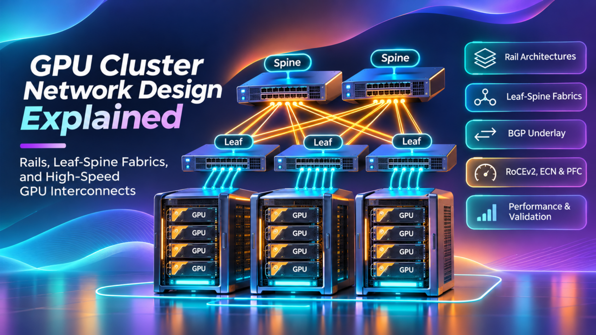
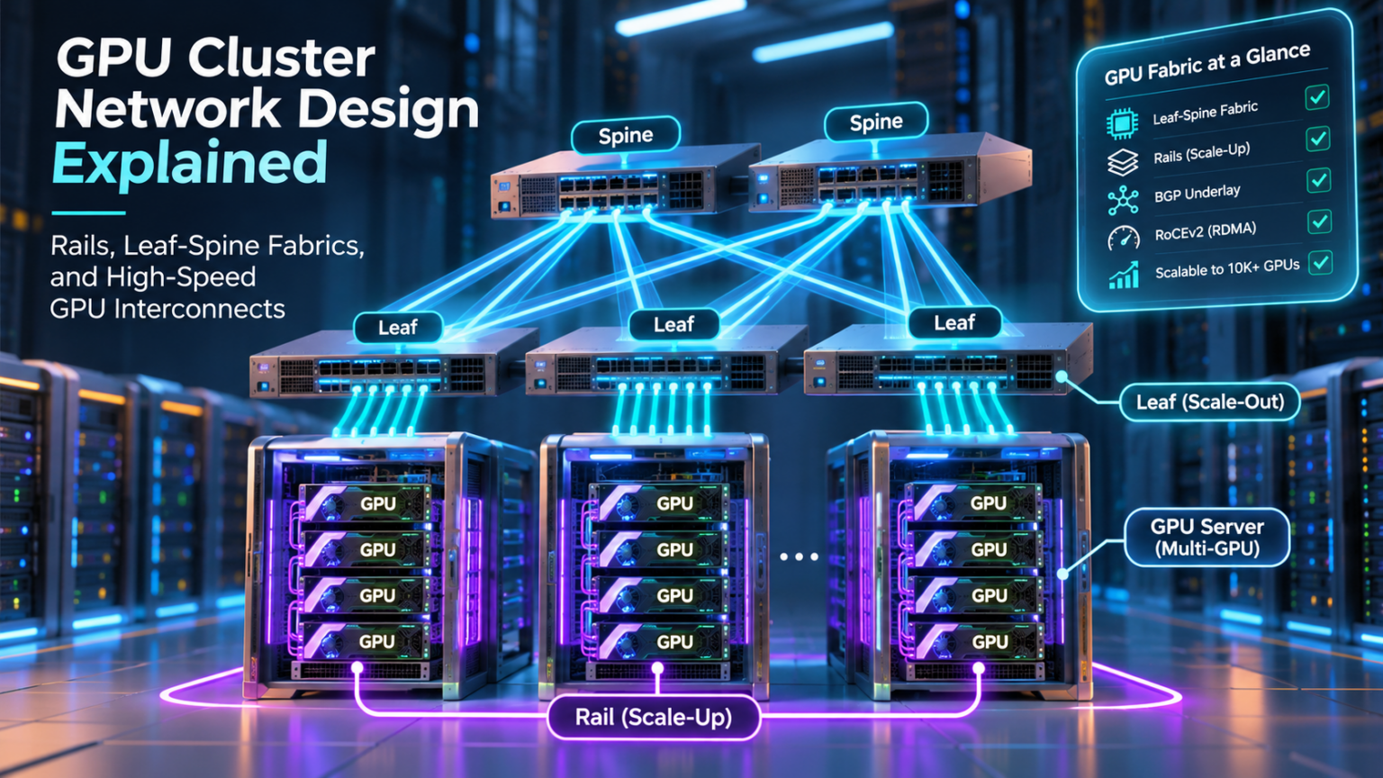
GPU Cluster Network Design Explained: Rails, Leaf-Spine Fabrics, and High-Speed GPU Interconnects
Modern GPU clusters require networks designed for high-throughput, latency-sensitive communication between accelerators. Understanding GPU-to-NIC connectivity, rail-optimised topologies, leaf-spine fabrics, and congestion behaviour is essential when building scalable AI infrastructure.
Traditional enterprise networks are commonly designed around application connectivity, availability, and north-south traffic flows. Distributed AI training introduces additional requirements because large groups of GPUs exchange data repeatedly during model execution.
These exchanges may involve AllReduce, AllGather, ReduceScatter, and other collective communication operations. Their performance is influenced by accelerator placement, PCIe connectivity, NIC bandwidth, switch topology, congestion management, and routing.
A well-designed GPU cluster must coordinate the compute and network architectures rather than treating them as independent systems.
Conceptual layers rather than a physical cabling diagram. Actual GPU-to-NIC affinity, port mapping, and fabric attachment depend on server architecture.
In this engineering guide, we examine the complete design process—from accelerator connectivity and rail architecture to bandwidth planning, fabric scaling, performance validation, and production operations.
Explore the GPU Cluster Network
Follow the engineering journey from GPU server architecture to production fabric design. Select a colored network node to jump directly to its section.
Understanding GPU Cluster Network Architecture
GPU cluster networks connect accelerators across servers and racks so that distributed AI workloads can exchange data efficiently. The architecture combines local GPU interconnects, server network adapters, high-speed switching fabrics, storage connectivity, and cluster management systems.
A GPU cluster consists of multiple compute nodes containing accelerators, CPUs, memory, and network adapters.
Distributed AI workloads use these resources collectively. Some communication occurs between GPUs inside a server, while other exchanges traverse network interfaces and external switches.
Understanding the architecture requires separating local accelerator communication from inter-server network communication.
1.1 The Main Components of a GPU Cluster
A production GPU cluster typically contains multiple infrastructure components that perform distinct functions.
GPU Compute Nodes
Servers containing accelerators, CPUs, memory, and high-speed network interfaces.
Network Adapters
Connect GPU servers to external fabrics using Ethernet or InfiniBand transport.
Network Fabric
High-speed switching infrastructure providing connectivity and aggregate bandwidth between compute nodes.
1.2 GPU Cluster Network Topology
Large AI clusters frequently use multi-stage switching topologies to connect GPU servers across racks.
A leaf-spine architecture provides multiple potential paths between compute nodes and can scale by adding switching capacity.
Simplified topology illustration. The connectors represent communication between tiers, not a complete cabling diagram. A real Clos fabric requires explicit leaf-to-spine links and capacity planning.
1.3 Scale-Up and Scale-Out Communication
GPU communication can be divided into two architectural categories: scale-up and scale-out.
Scale-up communication generally refers to accelerator connectivity within a tightly coupled compute system, often using technologies such as NVLink or NVSwitch where supported.
Scale-out communication connects accelerators across separate compute nodes using external networking technologies such as Ethernet with RoCEv2 or InfiniBand.
| Characteristic | Scale-Up | Scale-Out |
|---|---|---|
| Communication Scope | Within a tightly coupled GPU system | Between compute nodes or systems |
| Common Technologies | NVLink, NVSwitch, PCIe | Ethernet/RoCEv2, InfiniBand |
| Primary Objective | Efficient local accelerator communication | Distributed communication across the cluster |
| Engineering Focus | Accelerator topology and memory access | Fabric bandwidth, congestion, routing and resilience |
1.4 Back-End, Front-End, and Storage Networks
Production GPU deployments often distinguish multiple network traffic domains.
The back-end compute network carries high-performance communication between distributed accelerators.
The front-end network supports application access, orchestration, services, and operational connectivity.
A storage network may provide access to training datasets, checkpoints, and distributed storage systems.
These functions may use separate physical networks or logical segmentation, depending on scale, performance, and operational requirements.
1.5 Communication Paths and Performance
A communication operation between GPUs on different servers may traverse multiple components.
The path can include GPU memory, local I/O connectivity, a network adapter, leaf and spine switches, and the destination server.
The exact path depends on hardware architecture, memory-transfer mechanisms, routing decisions, and workload placement.
1.6 Engineering Considerations for GPU Cluster Design
The architecture must be evaluated as a complete system rather than a collection of individual high-speed links.
Network bandwidth should be matched to accelerator communication requirements.
Fabric topology must provide adequate path diversity and capacity for the expected workload.
Operational visibility must extend across GPU activity, network adapters, switching queues, and collective communication performance.
1.7 GPU Cluster Architecture Checklist
GPU Cluster Architecture Connects Compute and Networking
GPU clusters combine accelerator interconnects, network adapters, high-speed switching fabrics, and distributed communication frameworks. Understanding these components and their relationships is the foundation for designing scalable, high-performance AI infrastructure.
GPU Cluster Architecture Explorer
Explore the physical and logical architecture of a GPU cluster. Select a network domain, inspect its components, trace traffic and investigate what happens when connectivity fails.
01 / Network domains
High-speed GPU communication between compute servers.
02 / GPU cluster topology
cluster:~$

Select a domain to begin investigation.
A GPU cluster is not a single flat network. Compute, storage, management and front-end connectivity serve different purposes. Production designs commonly use separate physical or logical network domains, depending on performance, security and operational requirements.
GPU Server and NIC Connectivity Design
GPU server networking begins inside the compute node. The relationship between accelerators, PCIe connectivity, CPUs, NUMA domains, and network adapters influences the performance of distributed AI communication.
High-performance GPU clusters require careful consideration of the internal server architecture.
Even when external network bandwidth is sufficient, communication performance can be limited by inefficient device placement, local I/O bottlenecks, or unsuitable GPU-to-NIC relationships.
The goal is to create efficient data paths between accelerator memory and the network fabric.
2.1 Internal GPU Server Architecture
A modern GPU server may contain multiple accelerators, one or more CPUs, PCIe switches, local accelerator interconnects, and several high-speed network adapters.
These devices are connected through a platform-specific hardware topology.
Some accelerators may have more direct access to particular network adapters, while other communication paths may traverse additional PCIe switches or CPU interconnects.
NVLink / NVSwitch Where Supported
Logical illustration only. It does not imply one-to-one GPU-to-NIC wiring, direct NVLink-to-NIC connectivity, or identical PCIe paths. Actual connectivity must be verified against the server platform topology.
2.2 PCIe Topology and GPU-to-NIC Affinity
PCI Express provides a major I/O communication mechanism within many GPU server platforms.
A GPU and network adapter may share a PCIe switch, connect through the same CPU root complex, or reside under different root complexes.
The relationship between these devices is commonly described as GPU-to-NIC affinity.
Good affinity can reduce unnecessary I/O traversal and help improve communication efficiency, depending on platform capabilities and workload.
Local I/O Topology
Understand PCIe switches, root complexes, lane capacity, and supported peer-to-peer communication paths.
NUMA Locality
Identify CPU socket boundaries and the potential cost of remote memory or cross-socket I/O access.
Adapter Affinity
Map GPUs to suitable network adapters and validate their effective communication performance.
2.3 NVLink and NVSwitch
NVLink is a high-bandwidth accelerator interconnect used by supported NVIDIA GPU platforms.
NVSwitch can provide switching connectivity between GPUs within supported accelerator systems.
These technologies support efficient local GPU communication and can reduce dependence on the external network for communication that remains inside the local accelerator domain.
However, local accelerator interconnects and external network adapters perform different functions. NVLink and NVSwitch do not automatically replace the Ethernet or InfiniBand fabric required for inter-node communication.
2.4 GPUDirect RDMA and GPU Memory Transfers
GPUDirect RDMA enables supported network adapters and GPUs to participate in direct memory-transfer operations involving GPU memory.
This can avoid staging the transferred payload through conventional CPU-memory copy paths.
The feature requires compatible GPUs, network adapters, drivers, software, and platform topology.
The exact data path and performance depend on the hardware and software implementation.
| Characteristic | Host-Memory Staging | GPUDirect RDMA |
|---|---|---|
| Data Path | Payload may be copied between GPU and host memory | Supported NIC accesses GPU memory for RDMA transfers |
| CPU Involvement | May require additional host-managed copy operations | Can reduce host involvement in payload movement |
| Performance | Additional memory copies can add overhead | Can reduce copy overhead and improve efficiency |
| Requirements | Conventional device and host-memory support | Compatible hardware, drivers, topology, and RDMA software |
2.5 NUMA Locality and CPU Socket Boundaries
Non-Uniform Memory Access architectures divide system resources into locality domains.
A network adapter connected to one CPU socket may have a different access path to a GPU associated with another socket.
Cross-socket communication can introduce additional latency or consume shared interconnect bandwidth.
Consequently, device placement should be assessed using the actual platform topology rather than assumed from GPU or NIC numbering.
2.6 GPU-to-NIC Mapping for Distributed Workloads
Distributed communication frameworks may select network interfaces according to device locality, available bandwidth, topology awareness, and runtime configuration.
A design with several high-speed NICs can provide substantial aggregate bandwidth, but this capacity is only useful when the workload and communication software can utilise it effectively.
GPU-to-NIC mappings should therefore be validated using real communication workloads and appropriate benchmarking tools.
nvidia-smi topo -m
can help
inspect GPU
and NIC
topology relationships.
Complement this
with PCIe,
NUMA, driver,
and RDMA
validation rather
than relying
on a
single topology
command.
2.7 Connectivity Design Checklist
GPU-to-NIC Topology Is Part of Network Design
High-speed external networking cannot compensate for every inefficient internal server path. Engineers must understand PCIe topology, NUMA locality, GPU-to-NIC affinity, accelerator interconnects, and GPUDirect RDMA to deliver predictable distributed AI performance.
GPU-to-NIC Affinity Mapper
Explore how GPUs, PCIe root complexes, CPU sockets, NUMA domains and network adapters influence communication paths inside a GPU server.
01 / Server connectivity controls
02 / GPU server interconnect topology
server:~$

Awaiting GPU-to-NIC analysis.
GPU-to-NIC affinity can affect the path used by DMA traffic, PCIe transactions and inter-socket communication. NUMA-local placement may reduce unnecessary cross-socket traffic, but actual performance depends on the server's PCIe switches, root complexes, GPU interconnects, platform firmware and GPUDirect RDMA support.
Rail-Optimised GPU Network Architecture
Rail-optimised networking organises GPU server network interfaces into corresponding fabric domains. This design can improve communication locality, distribute aggregate traffic across multiple adapters, and provide a structured approach to scaling large AI clusters.
GPU servers commonly contain multiple high-speed network adapters. These interfaces can be organised into separate logical or physical network rails.
A rail represents a defined connectivity domain between network interfaces and the wider switching infrastructure.
In a rail-optimised design, corresponding network adapters across compute nodes connect to a consistent network domain.
3.1 What Is a GPU Network Rail?
A network rail is a grouping of server network interfaces and their associated fabric connectivity.
For example, NIC 0 on multiple GPU servers may connect through Rail 0, while NIC 1 connects through Rail 1.
This arrangement can simplify network design and help communication software use multiple network paths.
However, rail optimisation does not automatically guarantee equal traffic distribution. Actual utilisation depends on workload behaviour, communication libraries, transport configuration, and routing.
3.2 Four-Rail GPU Network Architecture
Consider a simplified deployment with four network adapters per GPU server.
Each adapter is associated with a separate network rail. Multiple compute nodes connect into the same rail domains.
Each column represents a logical rail. The illustration does not imply that each rail requires a single switch, that rail fabrics are always isolated, or that the topology provides automatic cross-rail failover.
3.3 NIC-to-Rail Mapping
Consistent NIC-to-rail mapping is an important design consideration for large GPU deployments.
A common approach is to associate a particular NIC position or locality group with the same rail across servers.
This mapping should reflect the actual server hardware topology and the requirements of the communication framework.
| GPU Server Interface | Example Rail | Design Objective |
|---|---|---|
| NIC 0 | Rail 0 | Consistent connectivity for the first adapter domain |
| NIC 1 | Rail 1 | Additional communication capacity and path separation |
| NIC 2 | Rail 2 | Parallel connectivity for supported multi-rail workloads |
| NIC 3 | Rail 3 | Further aggregate bandwidth and topology flexibility |
3.4 Rail Locality and Communication Efficiency
Rail locality refers to keeping traffic within the intended network domain when this is beneficial and supported by the application.
For example, a communication flow using NIC 0 on one server may communicate with a corresponding interface on another server through Rail 0.
The aim is to reduce unnecessary cross-rail traversal and maintain predictable communication paths.
Not all workloads follow fixed rail affinity. Some communication libraries may distribute data across multiple interfaces or choose different paths based on topology and runtime conditions.
3.5 Physical and Logical Rail Isolation
Rails can be implemented using separate switching infrastructure or through logical segmentation on shared hardware.
Physical isolation may provide clearer fault boundaries and independent switching resources.
Logical isolation may reduce infrastructure duplication but can leave rails sharing common capacity and failure dependencies.
Physical Rails
Dedicated switching and cabling domains with stronger physical separation.
Logical Rails
Segmented connectivity over shared switching infrastructure, subject to shared resource constraints.
Hybrid Designs
Combine dedicated high-performance fabric domains with selected shared management or service connectivity.
3.6 Bandwidth Aggregation and Multi-Rail Utilisation
Multiple high-speed network adapters provide the potential for substantial aggregate communication bandwidth.
For example, four 400 Gb/s interfaces represent 1.6 Tb/s of nominal aggregate link capacity in one direction.
However, effective application throughput will be lower and depends on protocol overhead, server I/O limits, communication patterns, congestion, and software efficiency.
A multi-rail fabric should therefore be evaluated using real workload measurements rather than theoretical link-speed totals alone.
3.7 Rail Failure Domains and Resilience
A rail can represent a distinct failure domain when its physical infrastructure is sufficiently independent.
Failure of a NIC, cable, switch, or fabric component may affect traffic assigned to that rail.
Recovery behaviour depends on the network design and communication software. Alternative rails do not automatically provide transparent failover for every RDMA connection or distributed workload.
3.8 Multi-Rail Design Checklist
Rail Optimisation Aligns Server Connectivity with Fabric Design
Multi-rail GPU networking provides a structured way to connect multiple server adapters to high-performance network fabrics. Effective designs depend on consistent NIC mapping, GPU locality, fabric capacity, traffic behaviour, and validated failure recovery.
GPU Rail Architecture Designer
Explore how corresponding NICs across GPU servers are aligned into independent network rails. Compare topology alignment, trace communication and investigate rail failures.
01 / Rail design controls
02 / Multi-server rail topology
rail:~$

Awaiting topology construction.
Rail-optimised architectures aim to keep corresponding GPU/NIC communication within aligned network rails, improving locality and simplifying fabric organisation. Actual rail designs depend on the GPU server architecture, number of NICs, routing model, workload mapping and collective communication implementation.
Designing the AI Leaf-Spine Fabric
High-performance GPU clusters require switching fabrics capable of supporting substantial east-west traffic, predictable forwarding paths, and scalable connectivity. Clos-based leaf-spine architectures provide a structured foundation for building high-speed AI compute networks.
A leaf-spine network uses multiple switching stages to connect compute nodes across a data centre.
Leaf switches provide connectivity to servers, while spine switches interconnect the leaf layer.
In a conventional two-tier Clos design, each leaf connects to every spine in its fabric domain.
This topology creates multiple equal-cost paths between leaves, subject to routing and forwarding configuration.
4.1 Clos and Leaf-Spine Architecture
Clos networks use multiple switching stages to scale connectivity beyond the port capacity of a single switch.
In a two-tier leaf-spine fabric, traffic between GPU servers attached to different leaves normally traverses a leaf, a spine, and another leaf.
Traffic between endpoints on the same leaf may remain local to that switch.
All-to-all leaf-to-spine connectivity is illustrated. The animated path is one possible route between Leaf 1 and Leaf 4. Actual traffic distribution depends on ECMP and transport behaviour.
4.2 Equal-Cost Multipath Routing
Equal-Cost Multipath, or ECMP, enables network devices to install multiple forwarding next hops for eligible routes.
In a leaf-spine network, ECMP can distribute traffic across multiple spine paths.
However, many implementations use flow-based hashing rather than distributing individual packets evenly across every available path.
As a result, a small number of large RDMA flows may experience uneven path utilisation even when multiple ECMP next hops are available.
4.3 BGP Underlay Routing
Ethernet-based AI fabrics frequently use Layer 3 routing in the underlay.
External BGP is one possible routing protocol for advertising infrastructure prefixes and establishing reachability between leaf and spine switches.
A common design uses eBGP sessions between directly connected leaves and spines, with a defined autonomous system numbering strategy.
ECMP eligibility, route installation, BGP multipath behaviour, and failure convergence must be validated on the selected switching platform.
Leaf-1:
  local-as: 65101
  router-id: 10.255.1.1

  neighbor Spine-1:
    peer-as: 65001
    address: 192.0.2.1

  neighbor Spine-2:
    peer-as: 65002
    address: 192.0.2.3

  advertise:
    10.10.1.0/24

  enable:
    BGP multipath where supported
    ECMP forwarding

Spine-1:
  local-as: 65001
  neighbor Leaf-1:
    peer-as: 65101
    address: 192.0.2.0
4.4 Switch Radix and Port Allocation
Switch radix describes the number of available ports or connectivity interfaces on a switching device.
The number of ports allocated to GPU servers versus spine uplinks determines the scale and capacity of the fabric.
For example, a 64-port switch using equal-speed interfaces could allocate 32 ports to servers and 32 ports to fabric uplinks.
This provides a nominal 1:1 ratio of server-facing to uplink bandwidth, assuming equal port speeds and no additional constraints.
4.5 Oversubscription and Fabric Capacity
Oversubscription occurs when the aggregate bandwidth of downstream interfaces exceeds available upstream capacity.
In general enterprise networks, some oversubscription is common because not every endpoint transmits at full capacity simultaneously.
Distributed GPU workloads may generate coordinated, high-volume communication that places much greater pressure on fabric links.
Therefore, the acceptable oversubscription ratio depends on the expected workload, traffic patterns, and performance objectives.
| Fabric Characteristic | Engineering Consideration | Potential Impact |
|---|---|---|
| Leaf-to-Spine Connectivity | Multiple uplinks and available paths | Path diversity and aggregate capacity |
| ECMP Distribution | Hashing behaviour and flow entropy | Possible link imbalance or hot spots |
| Switch Radix | Server ports versus uplink ports | Cluster scale and oversubscription |
| Routing Convergence | BGP timers, BFD, hardware behaviour | Traffic disruption during failures |
| Buffer and Queue Design | Congestion handling and traffic classes | Latency, drops, and RDMA performance |
4.6 Integrating Multi-Rail GPU Networks
A large GPU cluster may use several network rails, each with its own switching topology.
Rail-aware leaf-spine design must consider how each server NIC connects into the fabric and how traffic remains within the intended communication domain.
Some designs use separate physical Clos fabrics for different rails, while others share switching infrastructure.
The choice affects capacity planning, fault isolation, operational complexity, and resilience.
4.7 Resilience and Failure Behaviour
A Clos topology provides alternative forwarding paths when multiple spines are available.
However, physical redundancy alone does not guarantee uninterrupted application communication.
Link or switch failures can trigger route changes, packet loss, congestion shifts, and transport recovery.
The network must be tested under realistic failure scenarios to determine its effect on distributed GPU workloads.
4.8 AI Leaf-Spine Engineering Checklist
Clos Fabrics Provide the Foundation for Scalable GPU Networking
A well-designed AI leaf-spine network combines high-speed switching, predictable ECMP forwarding, scalable BGP underlay routing, adequate fabric capacity, and resilient physical connectivity. The design must be validated against the actual communication requirements of distributed GPU workloads.
BGP Fabric Control-Plane Lab
Investigate BGP underlay routing across a GPU leaf-spine fabric. Establish sessions, advertise prefixes, inspect ECMP paths and simulate link or route failures.
01 / Underlay routing controls
02 / GPU leaf-spine BGP topology
fabric:~$

BGP sessions are not established.
eBGP can provide scalable underlay routing in GPU leaf-spine fabrics. Multiple spines can provide equal-cost paths to destination prefixes, subject to BGP best-path and multipath eligibility. Link failures, session loss and route withdrawal can change the available forwarding paths.
GPU Cluster Bandwidth and Capacity Planning
GPU network capacity planning translates accelerator communication requirements into NIC bandwidth, switch port allocations, fabric uplink capacity, and scalable network infrastructure. Effective design requires balancing theoretical link speed with practical workload performance.
Distributed GPU workloads can generate substantial network traffic during training, synchronisation, and collective communication.
The required network capacity depends on the number of GPU servers, NIC interfaces, link speeds, workload communication patterns, and acceptable congestion.
Capacity planning must consider both server-facing bandwidth and the available fabric transport capacity.
5.1 Understanding GPU Server Network Bandwidth
A GPU server may contain multiple high-speed network adapters.
The nominal aggregate bandwidth is calculated by multiplying the number of NIC interfaces by their individual link speeds.
5.2 400G and 800G Network Interfaces
High-speed GPU fabrics may use 400 Gb/s or 800 Gb/s Ethernet interfaces, depending on the platform and deployment generation.
Higher-speed links can reduce the number of physical ports required for a given bandwidth target, but they also introduce considerations around optics, cabling, power, switch capability, and cost.
| Interface Speed | Four Interfaces | Eight Interfaces |
|---|---|---|
| 100 Gb/s | 400 Gb/s | 800 Gb/s |
| 200 Gb/s | 800 Gb/s | 1.6 Tb/s |
| 400 Gb/s | 1.6 Tb/s | 3.2 Tb/s |
| 800 Gb/s | 3.2 Tb/s | 6.4 Tb/s |
5.3 Mapping Server Bandwidth to the Fabric
The total server-facing bandwidth must be supported by the leaf switching infrastructure.
Leaf switches connect GPU servers to the wider fabric, while spine switches provide connectivity between leaves.
Fabric capacity must therefore account for both the number of attached interfaces and the required inter-leaf traffic bandwidth.
Conceptual capacity model. Multiple server NICs may attach to different rails and different leaf switches. This diagram does not prescribe a particular physical cabling layout.
5.4 Switch Radix and Port Budgets
Switch radix determines the available port resources for connecting GPU servers and fabric uplinks.
A switch with 64 equal-speed ports could, for example, allocate 32 ports to GPU servers and 32 ports to spine uplinks.
If all ports operate at 400 Gb/s, this gives 12.8 Tb/s of nominal server-facing capacity and 12.8 Tb/s of nominal uplink capacity.
This is a 1:1 bandwidth allocation, assuming no additional restrictions.
5.5 Oversubscription in AI Fabrics
Oversubscription is an important architectural decision because distributed AI workloads may generate coordinated bursts of communication.
A fabric designed with substantial oversubscription may experience congestion when many GPU nodes exchange data simultaneously.
However, the need for a non-oversubscribed fabric depends on workload behaviour and the proportion of traffic that crosses the relevant fabric boundary.
Non-Oversubscribed
Equal nominal downstream and upstream capacity at the measured network boundary.
Moderate Oversubscription
Downstream capacity exceeds uplink capacity, requiring workload analysis and congestion testing.
Higher Oversubscription
Lower uplink capacity relative to attached interfaces; potentially unsuitable for demanding all-to-all traffic.
5.6 Spine Capacity Planning
Spine switches provide the transport paths between leaf switches.
The required spine capacity depends on the number of leaves, the number of uplinks per leaf, and the speed of each uplink.
For a simple Clos topology, the total leaf uplink count can be estimated from the number of leaves multiplied by uplinks per leaf.
5.7 Capacity Planning for Multi-Rail Fabrics
Multi-rail GPU clusters may distribute network interfaces across several fabric domains.
Each rail must be sized for the traffic assigned to it.
Aggregate cluster capacity should not be calculated without considering rail boundaries, GPU-to-NIC affinity, and the communication framework's ability to utilise available paths.
5.8 Growth, Resilience, and Spare Capacity
Production capacity planning should include expansion headroom and failure scenarios.
Adding more GPU nodes may require additional leaf ports, spine capacity, optics, and cabling.
A fabric that is nominally non-oversubscribed during normal operation may become constrained when a spine or uplink fails.
Engineers should therefore assess both normal-state and degraded-state network capacity.
5.9 GPU Fabric Capacity Planning Checklist
Capacity Planning Must Follow the GPU Communication Model
A scalable AI fabric requires more than high-speed interfaces. Engineers must coordinate GPU server bandwidth, switch radix, uplink capacity, oversubscription, spine sizing, rail boundaries, and expansion headroom to create a network capable of supporting distributed AI workloads.
AI Switch Port Budget Calculator
Calculate switch port allocations, leaf-spine capacity and oversubscription for GPU clusters. Explore hardware limits before deploying a production AI fabric.
01 / Fabric hardware configuration
02 / Per-leaf switch port allocation
| Capacity parameter | Calculated value |
|---|
capacity:~$

Awaiting hardware sizing calculation.
Switch radix and link speed determine the number of server-facing and spine-facing connections a leaf can support. A feasible GPU fabric must also satisfy spine port budgets, cabling, transceiver compatibility, breakout constraints and future growth. Oversubscription is a capacity relationship, not a guarantee of workload performance.
Congestion Management in GPU Fabrics
Distributed GPU workloads can generate highly coordinated traffic bursts that place pressure on switch buffers and network queues. Effective congestion management combines proactive rate control, queue monitoring, and carefully engineered loss-avoidance mechanisms.
High-performance AI networks must support substantial data movement between GPU servers.
Collective communication operations may cause many endpoints to transmit data within the same time window.
When incoming traffic exceeds the available egress capacity, switch queues begin to grow.
If congestion persists, the network may experience increased latency, packet drops, or pause propagation.
6.1 Why GPU Workloads Create Congestion
Distributed training frameworks coordinate communication between many accelerators.
Some operations produce sustained high-throughput traffic, while others create short bursts involving many senders.
These traffic patterns can concentrate demand on particular egress ports or switching paths.
Congestion is especially important for RDMA transports because packet loss and transport recovery can affect collective communication performance.
6.2 Incast Traffic and Queue Pressure
Incast occurs when multiple senders transmit toward a common destination or shared egress resource.
If the aggregate arrival rate exceeds the egress link capacity, packets accumulate in the switch queue.
The resulting queue pressure can increase latency and trigger congestion signalling.
6.3 ECN — Explicit Congestion Notification
Explicit Congestion Notification allows compatible network devices to mark ECN-capable packets when congestion conditions are detected.
Instead of immediately dropping every packet that encounters a congestion threshold, the network can provide feedback to the transport endpoints.
For RoCEv2 deployments, ECN markings can contribute to congestion notification mechanisms that cause senders to adjust transmission rates.
6.4 PFC — Priority Flow Control
Priority Flow Control is an IEEE 802.1Qbb mechanism that allows pause behaviour to be applied to selected traffic priorities.
PFC can help prevent packet loss caused by buffer exhaustion for a configured priority.
However, excessive PFC activity can create operational problems, including pause propagation, head-of-line blocking, and potentially deadlock-related conditions in poorly designed environments.
PFC should therefore be treated as a carefully engineered protection mechanism rather than the primary solution to persistent congestion.
6.5 DCQCN — Data Centre Quantized Congestion Notification
DCQCN is a congestion-control approach used in many RoCEv2 environments.
It uses congestion feedback to influence sender transmission rates.
In a typical feedback sequence, a switch marks an ECN-capable packet, the receiver detects the marking, and a congestion notification is returned to the sender.
The sender can then adjust its rate according to the congestion-control algorithm.
RDMA Sender
ECN Marking
RDMA Receiver
ECN marks eligible IP packets. In RoCEv2, the receiver may generate a congestion notification packet (CNP) to influence sender transmission behaviour. PFC operates separately at the Ethernet link level.
6.6 ECN, PFC, and DCQCN Compared
| Mechanism | Primary Function | Engineering Consideration |
|---|---|---|
| ECN | Marks packets to indicate congestion | Requires suitable thresholds and compatible endpoints |
| PFC | Pauses selected Ethernet traffic priorities | Can prevent drops but may propagate congestion |
| DCQCN | Adjusts RDMA sender rates using congestion feedback | Requires appropriate tuning and compatible RoCEv2 implementation |
| Queue Scheduling | Allocates service to traffic classes | Influences fairness, latency, and isolation |
6.7 Queue Design and Traffic Classes
AI Ethernet fabrics may use dedicated traffic classes and queue configurations for selected RDMA workloads.
Queue design should consider the traffic classification model, available switch buffers, scheduling behaviour, and congestion thresholds.
Incorrect classification can place traffic into unintended queues, causing performance problems even when physical links have adequate capacity.
Early Congestion Signalling
Mark eligible packets before persistent queue growth creates severe congestion.
Selective Pause Protection
Protect configured traffic priorities while monitoring pause frequency and duration.
Endpoint Rate Control
Use congestion feedback to reduce sustained offered load and improve fabric stability.
6.8 Head-of-Line Blocking and Pause Propagation
Head-of-line blocking occurs when queued traffic delays other traffic that might otherwise make progress.
PFC can contribute to this problem when a paused priority affects traffic sharing the same resources.
Congestion may also spread beyond the original bottleneck through repeated pause behaviour.
Engineers should monitor pause events, queue occupancy, ECN markings, packet drops, and application performance together.
6.9 Monitoring Congestion in Production
Network monitoring should provide visibility into both sustained congestion and short-duration traffic bursts.
Average interface utilisation alone may not reveal microbursts or queue pressure.
Useful telemetry includes queue depth, ECN marking rates, PFC pause counters, discards, and RDMA congestion statistics.
6.10 Congestion Engineering Checklist
Effective Congestion Control Requires Coordinated Feedback
High-performance GPU fabrics require coordinated queue management, ECN marking, endpoint congestion control, selective pause protection, and detailed telemetry. The objective is to sustain useful throughput while preventing congestion from spreading across the AI network.
GPU QoS and Queue Policy Designer
Configure traffic classes, priority queues, ECN, PFC and DCQCN assumptions for an AI Ethernet fabric. Validate the policy and identify configuration risks before deployment.
01 / QoS policy controls
02 / Switch queue policy map
switch:~$

Awaiting QoS policy validation.
Congestion control in RoCEv2 fabrics requires coordinated switch and endpoint configuration. ECN can provide early congestion signalling, DCQCN can react to congestion notifications, and PFC may provide priority-specific backpressure. Poor threshold selection or excessive PFC scope can cause head-of-line blocking, congestion spreading and operational risk.
GPU Cluster Scaling and Failure Domains
Large GPU clusters must scale beyond individual servers and racks while maintaining predictable network capacity, operational visibility, and controlled failure domains. Resilient design requires coordination between physical infrastructure, routing, transport, and distributed application recovery.
GPU clusters often begin with a relatively small number of compute nodes.
As the environment grows, additional racks, network interfaces, leaf switches, and spine capacity may be required.
Scaling introduces challenges involving physical cabling, port availability, network convergence, failure isolation, and workload placement.
The objective is to expand the cluster without creating unpredictable performance or operational dependencies.
7.1 Scaling from GPU Servers to Compute Racks
The first level of scaling involves adding GPU servers within a rack.
These servers connect to leaf switches or other rack-level network infrastructure.
As the number of attached NICs increases, engineers must consider available switch ports, optics, cable routes, and uplink capacity.
Rack-level scaling also introduces power, cooling, and physical space constraints that can influence network architecture.
7.2 Multi-Rack GPU Cluster Architecture
Larger deployments connect multiple GPU racks through a shared or rail-specific switching fabric.
Each rack may contain several GPU nodes and one or more leaf switches.
Spine switches provide inter-rack connectivity within the relevant fabric domain.
Simplified compute-pod illustration. Each leaf is connected to all three spines. Production deployments may use multiple leaf switches per rack, separate rail fabrics, and additional switching stages.
7.3 GPU Compute Pods and Scaling Boundaries
A compute pod is a logical or physical grouping of GPU servers and supporting infrastructure.
Pod boundaries can help organise network design, capacity planning, deployment procedures, and operational responsibility.
A pod may share common switching infrastructure, power systems, storage access, or management services.
However, a logical pod boundary does not necessarily represent an independent failure domain.
7.4 Understanding GPU Cluster Failure Domains
A failure domain describes the set of components or services that may be affected by a particular failure.
GPU clusters contain several overlapping failure domains.
| Failure Domain | Example Failure | Potential Impact |
|---|---|---|
| GPU or NIC | Accelerator fault or network adapter failure | Loss of local compute or communication capability |
| Server | Power, firmware, or operating system failure | Loss of all workloads and interfaces on the node |
| Rack | Rack power distribution or cooling issue | Multiple compute nodes unavailable |
| Leaf Switch | Switch or server-facing port failure | Connectivity loss for affected attached interfaces |
| Spine Switch | Spine or fabric uplink failure | Reduced path diversity and aggregate capacity |
| Network Rail | Shared rail infrastructure failure | Communication disruption across associated NICs |
| Shared Services | Storage, identity, or orchestration outage | Potential impact across otherwise healthy compute nodes |
7.5 Redundancy and Path Diversity
Network redundancy reduces dependence on individual links and switching components.
In a leaf-spine topology, multiple spines provide alternative forwarding paths between leaves.
ECMP may distribute eligible traffic across those paths during normal operation.
If a spine or link fails, the routing and forwarding system must remove the unavailable path and use remaining connectivity.
Redundancy must also consider shared dependencies, including cabling routes, power feeds, and management infrastructure.
Physical Resilience
Independent cables, optics, switches, and power infrastructure where required.
Routing Resilience
Multiple next hops, failure detection, route withdrawal, and forwarding convergence.
Workload Resilience
Checkpointing, process recovery, job restart, and distributed framework fault handling.
7.6 BGP Convergence and Failure Detection
Ethernet leaf-spine fabrics may use eBGP to maintain underlay reachability.
When a link or neighbour fails, the network must detect the event and update forwarding state.
Mechanisms such as physical link-state detection, BGP session state changes, and Bidirectional Forwarding Detection may contribute to convergence.
Convergence time depends on platform capabilities, protocol settings, forwarding implementation, and the failure scenario.
7.7 RDMA and Distributed Workload Recovery
Network path recovery and application recovery are not the same process.
A routing protocol may restore network reachability, but an existing RDMA communication operation may still experience timeouts, errors, or connection failure.
Distributed training frameworks may require application-level recovery, process restart, or restoration from checkpoints.
7.8 Scaling Beyond a Single Fabric
Very large GPU deployments may exceed the practical capacity of a single two-tier leaf-spine fabric.
Additional switching stages, separate fabric domains, or hierarchical connectivity may be required.
These designs introduce additional considerations involving hop count, inter-domain bandwidth, fault isolation, and workload locality.
Expansion should therefore be planned around a defined capacity and topology model rather than ad hoc addition of switches.
7.9 Scaling and Failure-Domain Checklist
Scalable GPU Networks Require Explicit Failure-Domain Design
Production GPU clusters must combine structured multi-rack scaling, resilient fabric connectivity, controlled failure domains, predictable routing convergence, and workload-level recovery. Network redundancy is essential, but the complete system must be tested to understand how failures affect distributed AI applications.
GPU Cluster Expansion and Failure-Domain Planner
Scale a GPU cluster across multiple racks, configure network redundancy and simulate failures to understand fault isolation, connectivity loss and recovery.
01 / Cluster expansion controls
02 / Cluster failure-domain topology
cluster:~$

Awaiting cluster design.
Scaling a GPU cluster increases the importance of failure-domain boundaries. Multiple rails can provide additional connectivity options, but recovery depends on the actual network architecture, endpoint configuration, routing and collective communication implementation. A surviving network path does not guarantee uninterrupted distributed training.
GPU Network Performance Testing
High-performance GPU networking must be validated using real measurements rather than theoretical interface speeds. Effective testing combines hardware topology inspection, RDMA transport benchmarks, collective communication workloads, and detailed fabric telemetry.
A GPU cluster may contain high-speed network adapters and a well-designed switching fabric, yet still deliver disappointing distributed workload performance.
The cause may involve GPU-to-NIC topology, PCIe limitations, RDMA configuration, congestion, path imbalance, or communication software.
Performance testing must therefore examine the complete communication path rather than isolated network components.
8.1 Establishing a Performance Testing Strategy
A structured testing programme should begin with hardware and topology validation.
Engineers then verify network transport performance, followed by collective communication benchmarks and representative application workloads.
The results should be compared against defined acceptance criteria.
The stages represent a recommended validation sequence, not an automated benchmark execution engine.
8.2 GPU and NIC Topology Validation
Before measuring network throughput, engineers should confirm that GPU and NIC placement matches the intended server design.
Topology inspection can reveal differences between local PCIe paths, NUMA domains, and accelerator interconnect relationships.
Unexpected topology relationships may indicate that a workload is using a less efficient communication path.
8.3 RDMA Throughput and Latency Testing
RDMA benchmarking tools can help measure network transport performance between compatible endpoints.
The
perftest
suite commonly
includes tools
such as
ib_write_bw,
ib_read_bw,
and
ib_write_lat.
These tools can be used in suitable InfiniBand and RoCE environments, depending on configuration and device support.
Testing should include different message sizes, queue depths, endpoint pairs, and concurrent communication patterns.
8.4 NCCL Collective Communication Benchmarks
The NVIDIA Collective Communications Library, or NCCL, provides communication primitives used in distributed GPU applications.
The nccl-tests benchmark suite can help evaluate collective operations across GPUs.
Examples include AllReduce, AllGather, ReduceScatter, and broadcast operations.
These tests provide a higher-level view of communication performance than a basic network throughput benchmark.
| Test Category | Example Tool | What It Helps Validate |
|---|---|---|
| GPU Topology | nvidia-smi topo | GPU, NIC, and platform locality relationships |
| RDMA Device Status | ibv_devinfo | RDMA device capabilities and port information |
| RDMA Bandwidth | ib_write_bw | RDMA write throughput under test conditions |
| RDMA Latency | ib_write_lat | RDMA write latency characteristics |
| GPU Collective Performance | nccl-tests | Distributed collective communication efficiency |
| Fabric Telemetry | Switch and NIC counters | Queue pressure, drops, ECN, PFC, and utilisation |
8.5 Example GPU Network Diagnostic Commands
Linux-based GPU systems provide several tools that can help inspect network connectivity and hardware topology.
# Inspect GPU and NIC topology
nvidia-smi topo -m

# List RDMA-capable devices
ibv_devices

# Inspect RDMA device capabilities
ibv_devinfo

# Inspect network interface state
ip -br link

# Inspect PCIe devices
lspci

# Inspect NUMA topology
numactl --hardware

# Example RDMA bandwidth test
# Receiver/server:
ib_write_bw -d mlx5_0

# Sender/client:
ib_write_bw -d mlx5_0 192.0.2.10
8.6 Interpreting NCCL Benchmark Results
NCCL benchmarks commonly report operation timing and bandwidth-related metrics.
Reported bandwidth values must be interpreted in the context of the specific collective operation.
For example, algorithm bandwidth and bus bandwidth are different metrics, and neither should be assumed to represent direct physical NIC throughput.
Results should be compared using consistent GPU counts, message sizes, process placement, and test configuration.
8.7 Diagnosing GPU Network Bottlenecks
Performance bottlenecks may originate at several layers of the system.
Compute and Topology
GPU affinity, PCIe capacity, NUMA locality, memory access, and local interconnects.
Transport and Adapter
RDMA settings, queue pairs, link state, driver behaviour, and congestion feedback.
Switching Fabric
ECMP imbalance, queue pressure, PFC activity, packet drops, and uplink capacity.
8.8 Fabric Telemetry and Performance Correlation
Network telemetry should be collected during benchmark execution.
Useful measurements include interface utilisation, queue occupancy, ECN markings, PFC pause counters, packet drops, and NIC congestion statistics.
Correlating these metrics with benchmark timing helps identify whether performance limitations originate in the network or elsewhere in the compute system.
8.9 Establishing Production Performance Baselines
A baseline provides a reference against which future performance changes can be measured.
Baselines should record hardware versions, driver versions, network configuration, benchmark parameters, and measured results.
Testing should be repeated after significant infrastructure changes, including firmware upgrades, routing modifications, and GPU cluster expansion.
8.10 GPU Network Testing Checklist
GPU Network Performance Must Be Measured End to End
A high-performance GPU fabric is validated through hardware topology inspection, RDMA transport benchmarks, NCCL collective tests, fabric telemetry, and repeatable application baselines. The objective is to identify bottlenecks across the complete GPU communication path rather than relying on nominal network speeds.
NCCL and RDMA Benchmark Workbench
Explore GPU fabric benchmarking through synthetic NCCL collective and RDMA test results. Compare workload sizes, network conditions, bandwidth and latency.
01 / Benchmark configuration
02 / Synthetic benchmark results
03 / Benchmark run history
| Run | Test | Condition | Gb/s | Time |
|---|
benchmark:~$

Awaiting benchmark execution.
NCCL collective benchmarks and RDMA microbenchmarks measure different aspects of GPU network performance. Results depend on message size, GPU count, communication algorithm, network topology, NIC placement, endpoint configuration and congestion. Compare measurements against a repeatable baseline rather than relying on a single throughput value.
Production GPU Cluster Reference Design
A production GPU cluster network combines high-speed server connectivity, rail-aware fabric design, scalable leaf-spine switching, routing, congestion management, resilience, and measurable performance validation. This reference architecture demonstrates how these components fit together into an engineered deployment.
GPU network design should begin with the requirements of the distributed workloads that will run on the cluster.
The physical network, server topology, transport configuration, and operational processes must be designed as a coordinated system.
The following reference design illustrates one possible approach to building a scalable Ethernet-based GPU cluster.
9.1 Example GPU Cluster Requirements
Consider a deployment containing 32 GPU compute servers.
Each server contains eight GPUs and four 400 Gb/s network interfaces dedicated to scale-out communication.
The network is organised into four logical rails, with each server contributing one NIC interface to each rail.
The nominal server-facing link capacity is calculated as:
32 servers × 4 NICs × 400 Gb/s = 51.2 Tb/s
This is the sum of one-direction nominal link rates across all server NICs. It is not a guaranteed application throughput measurement.
9.2 End-to-End GPU Network Architecture
The reference architecture separates the GPU compute fabric from supporting infrastructure services.
GPU servers connect through high-speed NICs to leaf switches. Spine switches provide connectivity between leaf switches within the relevant fabric domain.
Logical illustration of one fabric domain. The 32-server reference design uses four NICs per server across four rails. A complete physical design requires additional rail-specific connectivity not shown here. Supporting service networks are shown conceptually rather than as physical links.
9.3 Rail-Optimised Server Connectivity
Each GPU server contributes four 400 Gb/s interfaces to the scale-out network.
A possible arrangement assigns one interface to each of four network rails.
Across 32 servers, each rail therefore contains 32 server-facing interfaces, representing 12.8 Tb/s of nominal aggregate one-direction capacity per rail.
Rail design should account for server PCIe topology, GPU affinity, physical switch placement, and the communication framework's rail utilisation behaviour.
9.4 Leaf and Spine Capacity Planning
Each rail must provide sufficient server-facing and uplink capacity for its expected traffic.
For example, a rail containing 32 server-facing 400 Gb/s ports requires 12.8 Tb/s of nominal downlink capacity.
A nominal 1:1 non-oversubscribed design at the leaf uplink boundary would allocate an equivalent 12.8 Tb/s of uplink capacity, assuming all relevant traffic must cross that boundary.
The actual number of leaf and spine switches depends on switch radix, supported port speeds, topology, and physical deployment constraints.
| Design Component | Illustrative Specification | Engineering Requirement |
|---|---|---|
| Compute Servers | 32 GPU servers | Validate power, cooling, and rack distribution |
| GPU Population | 8 GPUs per server, 256 total | Confirm GPU interconnect and PCIe topology |
| Scale-Out NICs | 4 × 400 Gb/s per server | Validate GPU-to-NIC affinity and RDMA capability |
| Rail Count | 4 logical rails | Define physical isolation and routing domains |
| Aggregate Server Links | 51.2 Tb/s nominal | Do not equate link capacity with application throughput |
| Routing | Example: eBGP underlay with ECMP | Verify multipath, convergence, and failure behaviour |
| RDMA Transport | Example: RoCEv2 | Validate NIC, switch, QoS, and congestion configuration |
| Operations | Telemetry, alerting, and acceptance testing | Establish measurable baselines and recovery procedures |
9.5 Routing and Forwarding Architecture
An Ethernet-based GPU fabric may use eBGP in the underlay to establish reachability between leaf and spine switches.
ECMP can provide multiple forwarding next hops across eligible fabric paths.
Routing policy, addressing, BGP session design, and convergence mechanisms should be standardised across the deployment.
The network should also be tested for path imbalance and changes in available capacity following failures.
9.6 RDMA and Congestion Management
Where RoCEv2 is selected, congestion management becomes an important component of the production design.
The fabric may use ECN, endpoint congestion control, and carefully configured Priority Flow Control.
These mechanisms should be tuned and validated together, with attention to queue occupancy, packet loss, pause propagation, and collective communication performance.
Routing and Reachability
BGP underlay, ECMP, path diversity, and failure convergence.
Transport Performance
NIC configuration, RoCEv2, congestion feedback, and traffic classification.
Production Operations
Telemetry, benchmarking, fault isolation, capacity monitoring, and change management.
9.7 Failure Domains and Recovery
Production designs must identify the impact of individual component failures.
These may include NIC failures, leaf switch failures, spine failures, rail outages, and shared infrastructure disruptions.
Network convergence should be measured separately from distributed application recovery.
A fabric may restore reachability while an existing RDMA operation or training job still requires recovery.
9.8 Production Deployment Sequence
Deploying a GPU cluster in defined stages makes it easier to isolate configuration problems and establish reliable performance baselines.
Validate Physical Infrastructure
Confirm racks, power, cooling, optics, cabling, and hardware inventory.
Deploy Fabric Underlay
Configure interfaces, addressing, routing, and ECMP behaviour.
Configure GPU Server Networking
Validate NIC drivers, RDMA devices, GPU affinity, and rail mapping.
Enable Congestion Controls
Configure traffic classes, queue behaviour, ECN, and PFC where required.
Run Performance Acceptance Tests
Measure RDMA bandwidth, latency, NCCL collective performance, and fabric telemetry.
Validate Resilience and Operations
Test failures, recovery, alerting, capacity thresholds, and operational procedures.
9.9 Production Acceptance Criteria
Acceptance criteria should be defined before the cluster enters production.
The criteria should cover connectivity, routing, throughput, latency, congestion, and recovery behaviour.
Performance thresholds must be based on the selected hardware, software, and representative workloads rather than generic assumptions.
9.10 Production Readiness Checklist
A Production GPU Fabric Is an End-to-End Engineering System
Successful GPU cluster networking requires server topology, high-speed NIC connectivity, rail-aware design, Clos switching, scalable routing, congestion control, resilient infrastructure, and measurable performance validation. These components must operate together to support predictable distributed AI workloads at production scale.
GPU Fabric Deployment and Validation Lab
Commission a production GPU network through six engineering validation gates. Run checks, diagnose faults, apply repairs and generate a simulated deployment acceptance report.
01 / Commissioning gates
02 / Engineering validation
Physical fabric readiness
Acceptance is pending. Complete all six validation gates before production handover.
commission:~$

Select a validation gate to begin.
Production readiness requires more than successful link establishment. A GPU fabric must demonstrate physical connectivity, correct routing, appropriate QoS policies, GPU-to-NIC locality, acceptable performance and documented failure behaviour. Evidence should be collected before declaring the network ready for workloads.

- Azure AI Architecture Explained - November 13, 2026
- GPU Cluster Network Design Explained - November 13, 2026
- Understanding AI Networking Architecture - November 13, 2026