

With the introduction and hype around Software Defined Networking ( SDN ) and Cloud Computing, one would assume that there has been little or no work with the advances in IP routing. You could say that the cloud has clouded the mind of the market. Regardless of the hype around this transformation, routing is still very much alive and makes up a vital part of the main internet statistics you can read. Packets still need to get to their destinations.
Advanced in IP Routing
The Internet Engineering Task Force (IETF) develops and promotes voluntary internet standards, particularly those that comprise the Internet Protocol Suite (TCP/IP). The IETF shapes what comes next, and this is where all the routing takes place. It focuses on anything between the physical layer and the application layer. It doesn’t focus on the application itself, but on the technologies used to transport it, for example, HTTP.
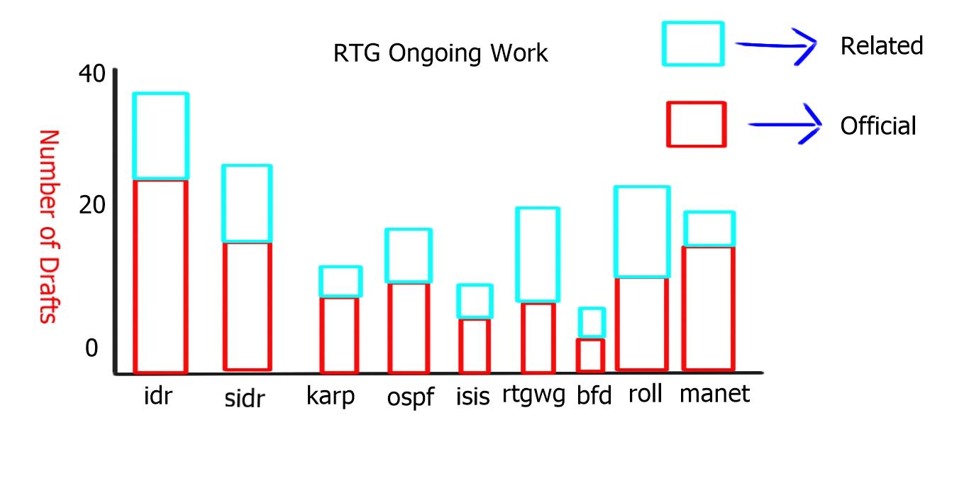
In the IETF, no one is in charge, anyone can contribute, and everyone can benefit. As you can see from the chart below, that routing ( RTG ) has over 250 active drafts and is the most popular working group within the IETF.

The routing area is responsible for ensuring the continuous operation of the Internet routing system by maintaining the scalability and stability characteristics of the existing routing protocols and developing new protocols, extensions, and bug fixes promptly
The following table illustrates the subgroups of the RTG working group:
| Bidirectional Forwarding Detection (BFD) | Open Shortest Path First IGP (OSPF) |
| Forwarding and Control Element Separation (forces) | Routing Over Low power and Lossy networks (roll) |
| Interface to the Routing System (i2rs) | Routing Area Working Group (RTGW) |
| Inter-Domain Routing (IDR) | Secure Inter-Domain Routing (SCIDR) |
| IS-IS for IP Internets (isis) | Source Packet Routing in Networking (spring) |
| Keying and Authentication for Routing Protocols (Karp) | |
| Mobile Ad-hoc Networks (manet) |
The chart below displays the number of drafts per subgroup of the routing area. There has been a big increase in the subgroup “roll,” which is second to BGP. “Roll” relates to “Routing Over Low power and Lossy networks” and is driven by the Internet of Everything and Machine-to-Machine communication.
OSPF Enhancements
OSPF is a link-state protocol that uses a common database to determine the shortest path to any destination.
Two main areas of interest in the Open Shortest Path First IGP (OSPF) subgroups are OSPFv3 LSA Extendibility and Remote Loop-Free Alternatives ( LFAs ). One benefit IS-IS has over OSPF is its ability to easily introduce new features with the inclusion of Type Length Values ( TLVs ) and sub-TLVs. The IETF draft-IETF-OSPF-ospfv3-lsa-extend extends the LSA format by allowing the optional inclusion of TLVs, making OSPF more flexible and extensible. For example, OSPFv3 uses a new TLV to support intra-area Traffic Engineering ( TE ), while OSPFv2 uses an opaque LSA.

Another shortcoming of OSPF is that it does not install a backup route in the routing table by default. Having a pre-installed backup up path greatly improves convergence time. With pre-calculated backup routes already installed in the routing table, the router process does not need to go through the convergence process’s LSA propagation and SPF calculation steps.
Loop-free alternatives (LFA)
Loop-Free Alternatives ( LFA ), known as Feasible Successors in EIGRP, are local router decisions to pre-install a backup path.
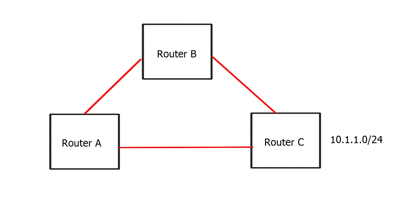
In the diagram below:
-Router A has a primary ( A-C) and secondary ( A-B-C) path to 10.1.1.0/24
-Link State allows Router A to know the entire topology
-Router A should know that Router B is an alternative path. Router B is a Loop-Free Alternate for destination 10.1.1.0/24
This is not done with any tunneling, and the backup route needs to exist for it to be used by the RIB. If the second path doesn’t exist in the first place, the OSPF process cannot install a Loop-Free Alternative. The LFA process does not create backup routes if they don’t already exist. An LFA is simply an alternative loop-free route calculated at any network router.
A drawback of LFA is that it cannot work in all topologies. This is most notable in RING topologies. The answer is to tunnel and to get the traffic past the point where it will loop. This effectively makes the RING topology a MESH topology. For example, the diagram below recognizes that we must tunnel traffic from A to C. The tunnel type doesn’t matter – it could be a GRE tunnel, an MPLS tunnel, an IP-in-IP tunnel, or just about any other encapsulation.
In this network:
-Router A’s best path through E
-Routers C’s best path is through D
-Router A must forward traffic directly to C to prevent packets from looping back.

In the preceding example, we will look at “Remote LFA,” which leverages an MPLS network and Label Distribution Protocol ( LDP ) for label distribution. If you use Traffic Engineering ( TE ), it’s called “TE Fast ReRoute” and not “Remote LFA.” There is also a hybrid model combining Remote LFA and TE Fast ReRoute, and is used only when the above cannot work efficiently due to a complex topology or corner case scenario.
Remote LFAs extend the LFA space to “tunneled neighbors”.
– Router A runs a constrained SPF and finds C is a valid LFA
– Since C is not directly connected, Router A must tunnel to C
a) Router A uses LDP to configure an MPLS path to C
b) Installs this alternate path as an LFA in the CEF table
– If the A->E link fails.
a) Router A begins forwarding traffic along the LDP path
The total time for convergence usually takes 10ms.
Remote LFA has some topology constraints. For example, they cannot be calculated across a flooding domain boundary, i.e., an ABR in OSPF or L1/L2 boundary is IS-IS. However, they work in about 80% of all possible topologies and 90% of production topologies.
BGP Enhancements
BGP is a scalable distance vector protocol that runs on top of TCP. It uses a path algorithm to determine the best path to install in the IP routing table and for IP forwarding.
Recap BGP route advertisement:
- RR client can send to a RR client.
- RR client can send to a non RR client.
- A non-RR client cannot send to a non-RR client.
One drawback to the default BGP behavior is that it only advertises the best route. When a BGP Route Reflector receives multiple paths to the same destination, it will advertise only one of those routes to its neighbors.
This can limit the visibility in the network and affect the best path selection used for hot potato routing when you want traffic to leave your AS as quickly as possible. In addition, all paths to exit an AS are not advertised to all peers, basically hiding ( not advertising ) some paths to exit the network.
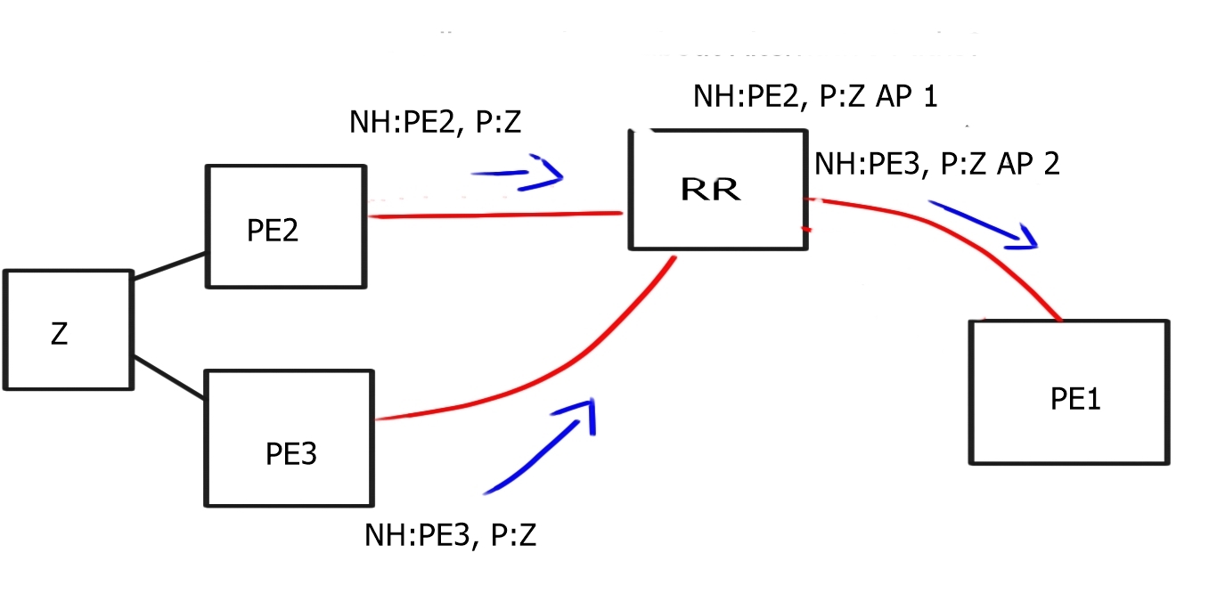
The diagram below displays default BGP behavior; the RR receives two routes from PE2 and PE3 about destination Z; due to the BGP best path mechanism, it only advertises one of those paths to PE1.

In certain designs, you could advertise the destination CE with different Route Distinguishers (RDs), creating two instances for the same destination prefix. This would allow the RR to send two paths to PE.
Diverse BGP path distribution
Another new feature is diverse BGP Path distribution, where you can create a shadow BGP session to the RR. It is easy to deploy, and the diverse iBGP session will announce the 2nd best path. Shadow BGP sessions are especially useful in virtualized deployments, where you can create another BGP session to a VM acting as a Route-Reflector. The VM can then be scaled out in a virtualized environment creating numerous BGP sessions. You are allowing the advertisements of multiple paths for each destination prefix.

BGP Add-path
A special extension to BGP known as “Add Paths” allows BGP speakers to propagate and accept multiple paths for the same prefix. The BGP Add-Path feature will signal diverse paths, so you don’t need to create shadow BGP sessions. There is a requirement that all Add-Path receiver BGP routers must support the Add-Path capability.
There are two flavors of the Add-Path capability, Add-n-path, and Add-all-path. The “Add-n-path” will add 2 or 3 paths depending on the IOS version. With “Add-all-path,” the route reflector will do the primary best path computation (only on the first path) and then send all paths to the BR/PE. This is useful for large ECMP load balancing, where you need multiple existing paths for hot potato routing.
Source packet routing
Another interesting draft the IETF is working on is Source Packet Routing ( spring ). Source Packet Routing is the ability of a node to specify a forwarding path. As the packet arrives in the network, the edge device looks at the application, determines what it needs, and predicts its path throughout the network. Segment routing leverages the MPLS data plane, i.e., push, swap, and pop controls, without needing LDP or RSVP-TE. This avoids millions of labels in the LDP database or TE LSPs in the networks.
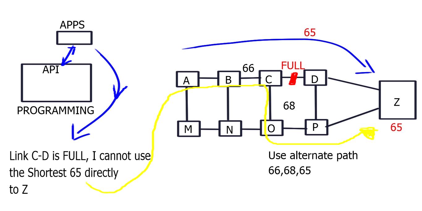 Diagram: Application Controls – Network Delivers
The complexity and state are now isolated to the network’s edges, and the middle nodes are only swapping labels. The source routing is based on the notion of a 32-bit segment that can represent any instructions, such as service, context, or IGP-based forwarding construct. This results in an ordered chain of topological and service instructions where the ingress node pushes the segment list on the packet.
Prefix Hijacking in BGP
BGP hijacking revolves around locating an ISP that is not filtering advertisements, or its misconfiguration makes it susceptible to a man-in-the-middle attack. Once located, an attacker can advertise any prefix they want, causing some or all traffic to be diverted from the real source towards the attacker.
In February 2008, a large portion of YouTube’s address space was redirected to Pakistan when the Pakistan Telecommunication Authority ( PTA ) decided to restrict access to YouTube.com inside the country but accidentally blackholed the route in the global BGP table.
These events and others have led the Secure-Inter Domain Routing Group ( SIDR ) to address the following two vulnerabilities in BGP:
-Is the AS authorized to originate an IP prefix?
-Is the AS-Path represented in the route the same as the path through which the NLRI traveled?
This lockdown of BGP has three solution components:
| RPKI Infrastructure | Offline repository of verifiable secure objects based on public-key cryptography |
| Follows resources (IPv4/v6 + ASN) allocation hierarchy to provide “right of use” | |
| BGP Secure Origin AS | You only validate the Origin AS of a BGP UPDATE |
| Solves most frequent incidents (*) | |
| No changes to BGP nor the router’s hardware impact | |
| Standardization is almost finished and running code | |
| BGP PATH Validation | BGPSEC proposal under development at IETF |
| Requires forward signing AS-PATH attribute | |
| Changes in BGP and possible routers |
The roll-out and implementation should be gradual and create islands of trust worldwide. These islands of trust will eventually interconnect together, making BGP more secure.
The table below displays the RPKI Deployment State;
| RIR | Total | Valid | Invalid | Unknown | Accuracy | RPKI Adoption Rate |
| AFRINIC | 100% | .44% | .42% | 99.14% | 51.49% | .86% |
| APNIC | 100% | .22% | .24% | 99.5% | 48.32% | .46% |
| ARIN | 100% | .4% | .14% | 99.46% | 74.65% | .54% |
| LACNIC | 100% | 17.84% | 2.01% | 80.15% | 89.87% | 19.85% |
| RIPE NCC | 100% | 6.7% | 0.59% | 92.71% | 91.92% | 7.29% |
Cloud Enhancements – The Intercloud
Today’s clouds have crossed well beyond the initial hype, and applications are now offered as on-demand services ( anything-as-a-service [XaaS] ). These services are making significant cost savings, and the cloud transition is shaping up to be as powerful as the previous one – the Internet. The Intercloud and the Internet of Things are the two new big clouds of the future.
Currently, the cloud market is driven by two spaces – the public cloud ( off-premise ) and the private cloud (on-premise). The intercloud takes the concept of cloud much further and attempts to connect multiple public clouds. A single application that could integrate services and workloads from ten or more clouds would create opportunities and potentially alter the cloud market landscape significantly. Hence, it is important to know and understand the need for cloud migration and its related problems.
We are already beginning to see signs of this in the current market. Various applications, such as Spotify and Google Maps, authenticate unregistered users with their Facebook credentials. Another use case is a cloud IaaS provider could divert incoming workload to another provider if it doesn’t have the resources to serve the incoming requests, essentially cloud bursting from provider to provider. It would also make economic sense to move workload and services between cloud providers based on cooling costs ( follow the moon ). Or maybe dynamically move workloads between providers, so they are closest to the active user base ( follow the sun )
The following diagram displays a Dynamic Workload Migration between two Cloud companies.
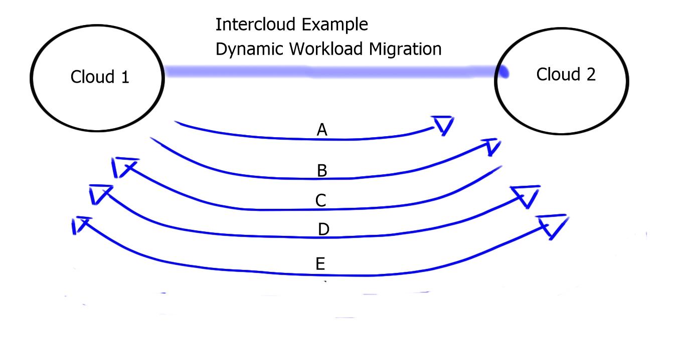
| A: Cloud 1 finds Cloud 2 | -Naming, Presence |
| B: Cloud 1 Trusts Cloud 2 | -Certificates, Trustsec |
| C: Both Cloud 1 and 2 negotiate | -Security, Policy |
| D: Cloud 1 sets up Cloud 2 | -Placement, Deployment |
| E: Cloud 1 sends to Cloud 2 | -VM runs in cloud-Addressing, configurations |
The concept of Intercloud was difficult to achieve with the previous version of vSphere based on the restriction of latency for VMotion to operate efficiently. Now vSphere v6 can tolerate 100 msec of RTT.
InterCloud is still a conceptual framework, and the following questions must be addressed before it can be moved from concept to production.
1) Intercloud security
2) Intercloud SLA management
3) Interoperability across cloud providers.
Cisco’s One Platform Kit (onePK)
The One Platform Kit is Cisco’s answer to Software Defined Networking. It aims to provide simplicity and agility to a programmatic network. It’s a set of APIs driven by programming languages, such as C and Java, that are used to program the network. We currently have existing ways to program the network with EEM applets but lack an automation tool that can program multiple devices simultaneously. It’s the same with Performance Routing ( PfR ). PfR can program and traffic engineer the network by remotely changing metrics, but the decisions are still local and not controller-based.
Traffic engineering
One useful element of Cisco’s One Platform Kit is its ability to perform “Off box” traffic engineering, i.e., the computation is made outside the local routing device. It allows you to create route paths throughout the network without relying on default routing protocol behavior. For example, the cost is the default metric for route selection for equal-length routes in OSPF. This cannot be changed, which makes the routing decisions very static. In addition, Cisco’s One Platform Kit (onePK) allows you to calculate routes using different variables you set, giving you complete path control.

- DMVPN - May 20, 2023
- Computer Networking: Building a Strong Foundation for Success - April 7, 2023
- eBOOK – SASE Capabilities - April 6, 2023