Understanding BGP Multipath
BGP Multipath refers to the capability of installing multiple paths to the same destination in the routing table. Traditionally, BGP only selects a single best path based on certain criteria, such as the shortest AS path length or the lowest path cost. However, with Multipath enabled, BGP can now consider and utilize multiple paths, enhancing network performance and resiliency.
**Multipath Considerations**
a. Increased Network Resilience: One of the key advantages of BGP Multipath is the increased network resilience it offers. By utilizing multiple paths, BGP can quickly adapt and reroute traffic in case of link failures or congestion. This redundancy helps to ensure uninterrupted connectivity and reduces the impact of network disruptions.
b. Load Balancing and Traffic Engineering: Another significant benefit of BGP Multipath is load balancing. Network administrators can optimize resource utilization and prevent network congestion by distributing traffic across multiple paths. This feature is particularly useful in scenarios where multiple links to the same destination have varying capacities.
c. Path Diversity and Performance Optimization: BGP Multipath also enables path diversity, allowing networks to explore alternative routes to a destination. This flexibility can lead to improved performance by bypassing congested or suboptimal links. Additionally, Multipath facilitates better control over traffic engineering, enabling network administrators to fine-tune the data flow and optimize network performance.
**How to Configure BGP Multipath**
Configuring BGP Multipath involves a few essential steps, depending on the specific network environment and equipment being used. Here’s a general overview of the configuration process:
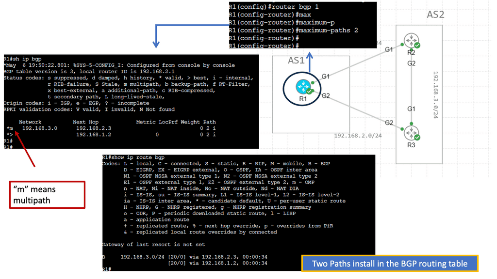
1. **Enable Multipath Support:** Begin by enabling BGP Multipath support on the router. This can usually be done through the router’s configuration interface, specifying the number of paths to be used.
2. **Adjust Path Selection Criteria:** Fine-tune the criteria used for selecting multiple paths to ensure they meet the network’s performance and reliability needs. This may involve setting attributes like AS path length and local preference.
3. **Monitor and Optimize:** After configuration, continuously monitor the network to ensure that BGP Multipath is performing as expected. Make adjustments as necessary to optimize performance and address any issues that arise.
Solution for BGP Multipath
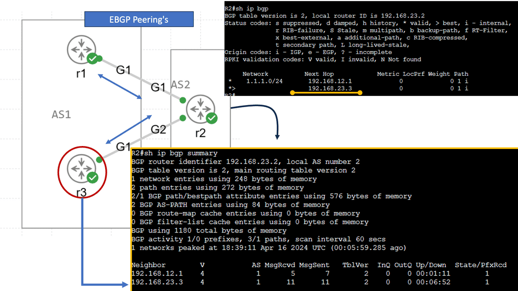
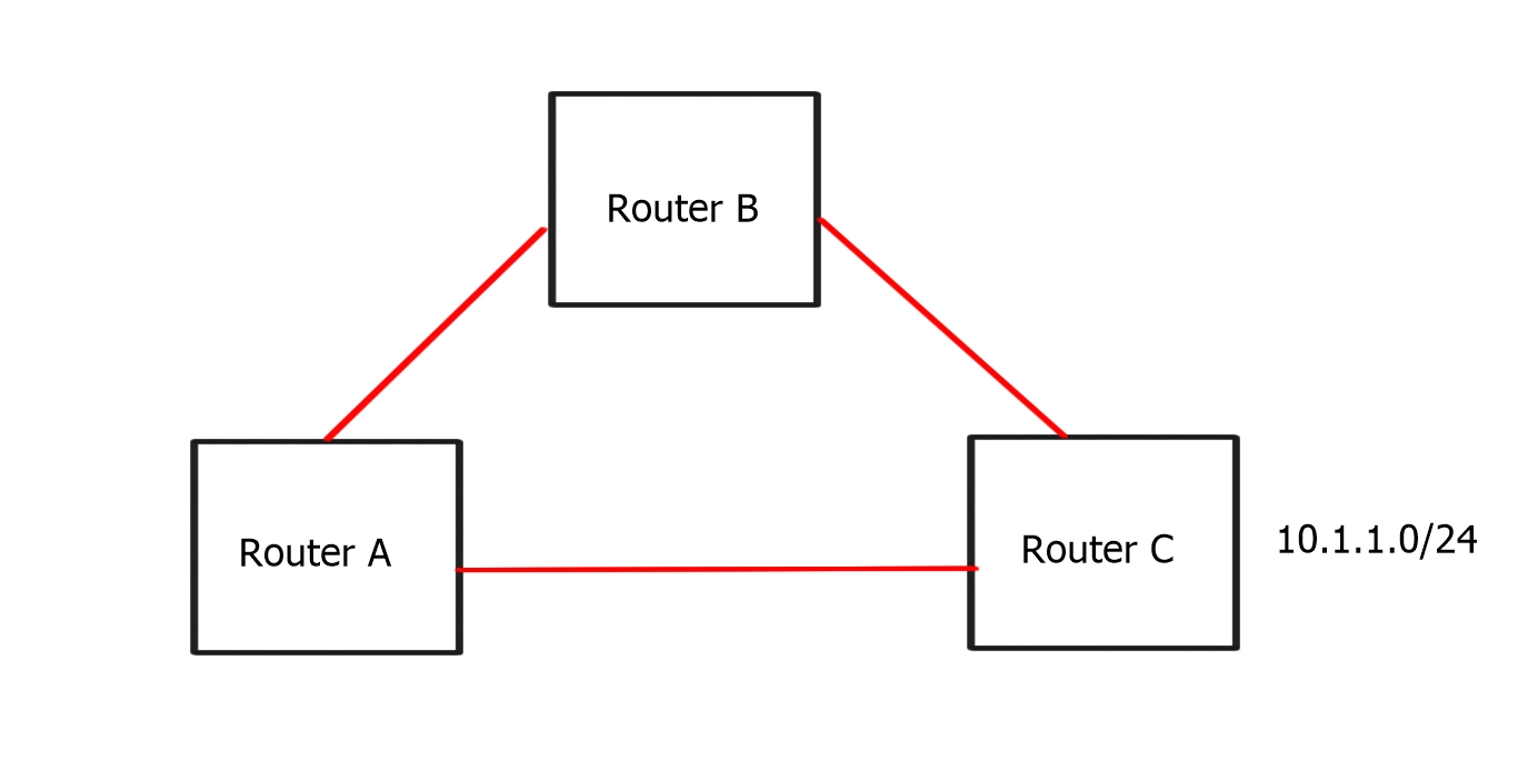
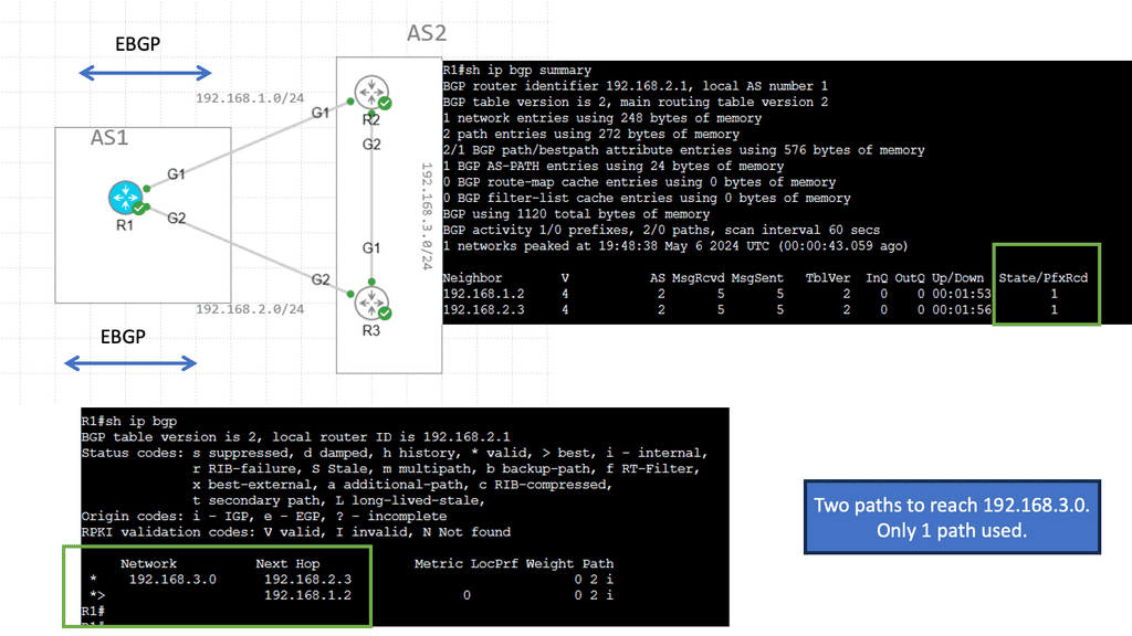
BGP multipath can also be used to share loads over multiple links. A separate BGP session is configured for each link between the two routers. BGP sessions are directly associated with interface addresses. As a result, each router receives a path for each link. There is only one difference between them: the neighbor address from which the path was received. Up to the maximum-paths value configured, the router can install all paths via eBGP multipath.
The enterprise border router and the provider router must be configured with the multipath feature. The provider may not desire BGP multipath since it can cause significant memory requirements, so eBGP multi-hop may be required. This is because the command to enable this feature is not specific to a particular peer or group of peers but to all BGP prefixes on the router.
In comparison to vanilla BGP, BGP multipath offers the following advantages:
Multiple links can be used to load-balance traffic.
Failures in BGP sessions or links have a reduced impact.
Having multiple paths installed ensures continuous forwarding and no packet loss in case of next-hop failures.
In the event of a failure, while multiple paths are active, the router must only remove the failed forwarding next hop rather than waiting for the RIB best path selection, FIB programming, and ASIC programming processes to complete. Only the failed path is affected, and all traffic to that destination is unaffected.
When two multipath links are in use, traffic has an approximately half-effect. Four links affect approximately one-quarter of a system, and so on.
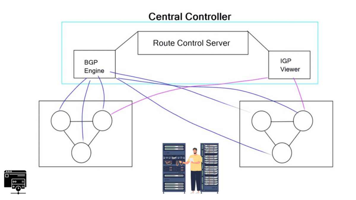
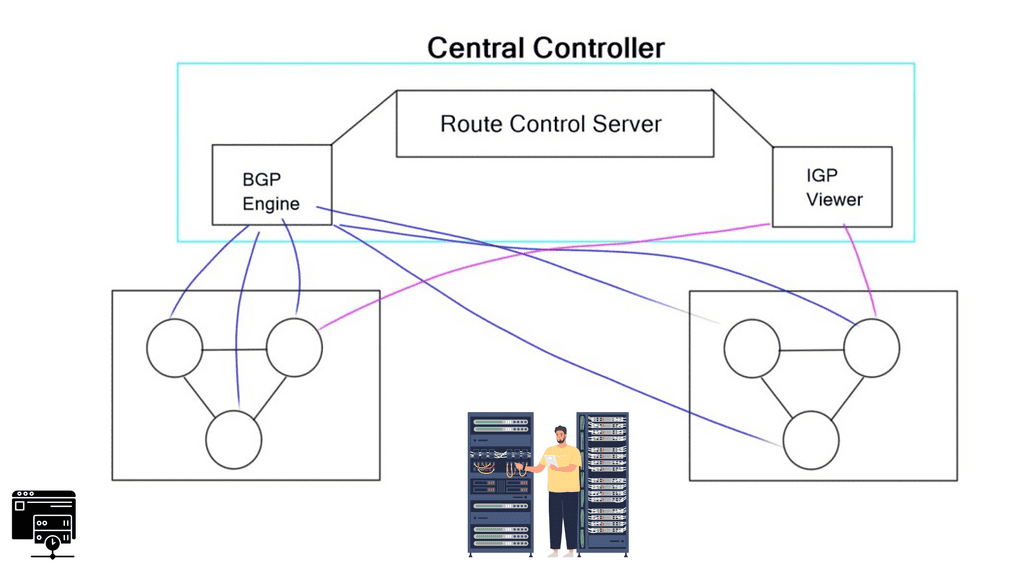
**The Role of BGP**
Border Gateway Protocol (BGP) was developed in 1989 to connect networks and provide interdomain routing. The goal was to create a scalable, non-chatty protocol. BGP grew in response to the overwhelming growth of the Internet, and its use cases now vary from Multicast, DDoS protection, Layer 2 services, BGP SDN, and the Routing Control Platform variations. A lot of its success comes down to the fact that it is a very well-known protocol.
**BGP Additional Features**
People know how to use BGP, and additional features are easily added, making it very extensible and easy to use. It’s much easier to troubleshoot a BGP problem than a complex IGP problem. If you want to add something new, you can create an attribute, and simple traffic engineering can be done using predefined BGP communities. Many tools are available within the protocol. Recently, there have been infrastructure improvements such as keepalive and update generation enhancements, parallel route refresh, adaptive update cache size, and multipath signaling.
Hands On – BGP Multipath
Understanding BGP Multipath
BGP Multipath allows routers to install multiple paths for the same destination in their routing tables. Traditionally, BGP selects only a single best path based on attributes like the shortest AS path length or the lowest path cost. However, Multipath enables routers to consider and utilize multiple paths concurrently, effectively distributing traffic across the available paths.
The utilization of multiple paths through BGP Multipath offers several advantages. First, it enhances network resiliency by providing redundancy. In the event of a link failure or congestion on one path, traffic can be automatically rerouted to alternative paths, ensuring uninterrupted connectivity. Additionally, BGP Multipath facilitates load balancing, allowing for efficient traffic distribution across multiple paths and optimizing network performance.
Implementing BGP Multipath involves configuration changes on the routers participating in the BGP routing process. Each router must be configured to enable Multipath and specify the maximum number of paths it can install in its routing table. Additionally, careful consideration should be given to the routing policies and attributes used for path selection to ensure optimal load balancing and redundancy.
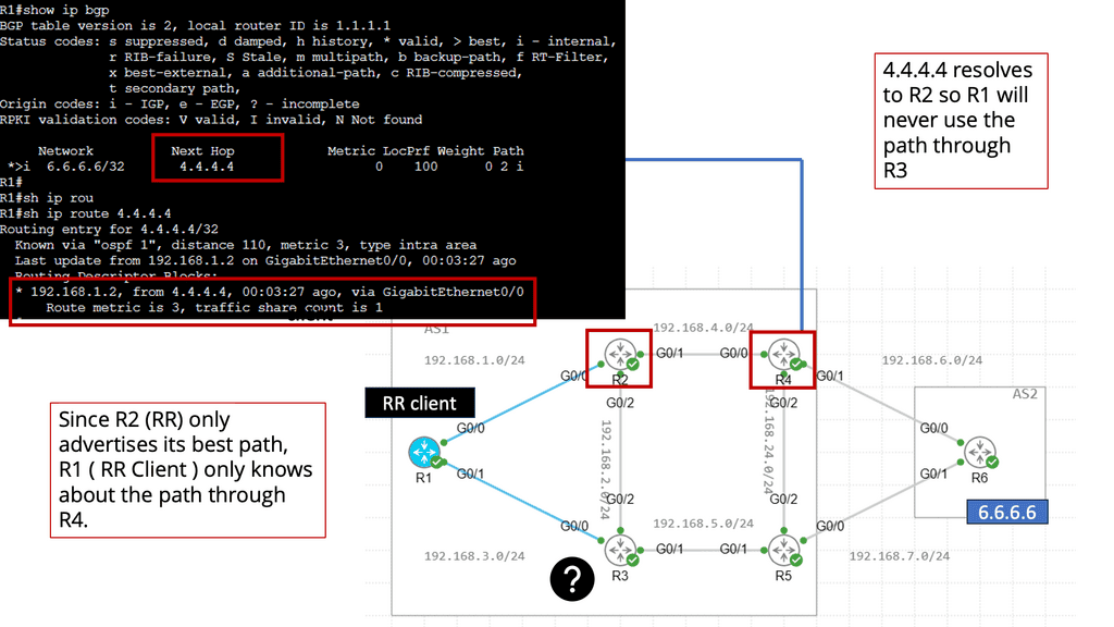
Knowledge Check: BGP Route Reflection
Understanding BGP Route Reflection
– BGP route reflection is a technique used to alleviate the full mesh requirement of BGP peering. In a traditional BGP setup, every router needs to establish a peering relationship with every other router in the network, resulting in a complex mesh of connections. Route reflection relaxes this requirement by introducing route reflector(s) to manage BGP updates and distribute routing information to other routers.
– Implementing BGP route reflection brings several advantages to large networks. First, it reduces required BGP peering connections, simplifying network design and configuration. This, in turn, improves scalability and lowers administrative overhead. Additionally, route reflection enhances network stability by preventing routing loops and reducing convergence time during network changes.
– To implement BGP route reflection, one or more route reflectors need to be deployed within the network. These reflectors serve as central points for receiving and distributing BGP updates. Routers within the network establish peering relationships with the reflectors, allowing them to exchange routing information. It is important to carefully design the route reflection hierarchy to ensure optimal route distribution and avoid potential bottlenecks.


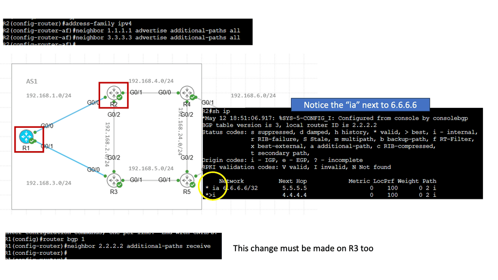
BGP Add Path
Understanding the BGP Additional Paths Feature
The BGP Additional Paths feature is an extension of BGP that enables routers to advertise multiple paths for the same destination prefix. Traditionally, BGP only advertised the best route based on its selection process. However, with the Additional Paths feature, routers can now advertise and maintain additional paths, allowing for better traffic distribution and more efficient routing decisions.
Enhanced Traffic Engineering: The Additional Paths feature gives network operators more control over network traffic flow. By advertising multiple paths, operators can select paths based on various criteria, such as link utilization, latency, or specific policy requirements. This enables better traffic engineering and load balancing, improving network performance and resiliency.
Fast Convergence: With multiple paths available, the BGP Additional Paths feature allows for faster convergence during network failures or changes. When a primary path becomes unavailable, routers can quickly switch to an alternate path, minimizing the impact on network traffic and reducing downtime. This feature is particularly crucial for networks that require high availability and rapid failover capabilities.
Multi-Exit Discriminator (MED) Manipulation: The Additional Paths feature can be utilized to manipulate Multi-Exit Discriminator (MED) attributes. MED is an optional attribute BGP uses to influence the path selection process among multiple entry points into an autonomous system. By advertising different paths with varying MED values, network operators can control inbound traffic and steer it through specific entry points, optimizing network resources and improving performance.
Advanced Topic:
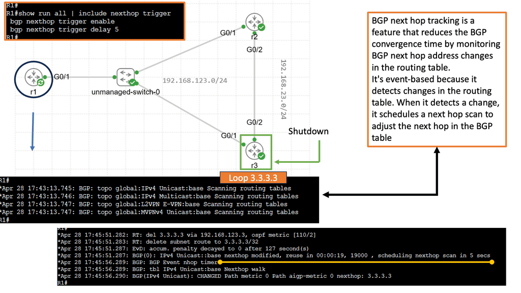
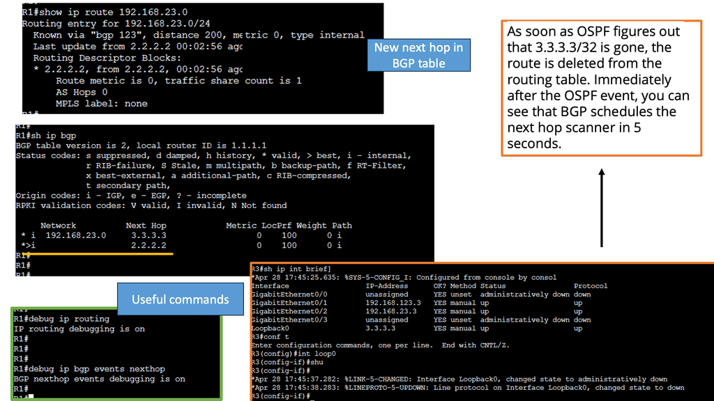
BGP Next Hop Tracking
BGP’s next hop is the IP address of the next router on the path towards the destination network. It is crucial in determining the best path for routing packets across the Internet. Network administrators gain valuable insights into the network’s routing decisions by tracking the next hop.
Next-hop tracking provides numerous benefits for network operators. First, it enables proactive monitoring of the network’s routing paths, allowing administrators to identify any routing anomalies or failures quickly. Second, it aids in troubleshooting network issues by pinpointing the exact location of potential problems. Third, it assists in load-balancing traffic across multiple paths, optimizing network performance.
Implementing BGP next-hop tracking requires careful configuration and the use of specialized tools. Network devices and routers must be configured to monitor and track the next hop for each BGP route. Various network monitoring software and platforms offer features designed explicitly for BGP next-hop tracking, providing real-time visibility and alerts.
BGP next-hop tracking has applications in various networking scenarios. It is especially valuable in multi-homed networks, where redundant connections are used for enhanced reliability. Network administrators can monitor the next hop of BGP routes to ensure traffic is routed through the desired path, preventing congestion and optimizing network resources.
For pre-information, you may find the following helpful
At a fundamental level, BGP multipath allows you to install multiple internal and external BGP paths to the forwarding table. Selecting multiple paths enables BGP to load-balance traffic across multiple links. This allows various BGP routes to simultaneously reach the same destination. The principal benefits of BGP multipath compared to normal BGP are:
- The capacity to load-balance traffic across multiple links.
- Decreased impact in the event of a BGP session or link failure.
By distributing traffic across multiple paths, BGP Multipath can help alleviate congestion on certain links, prevent bottlenecks, and optimize network utilization. It can also improve resiliency and reliability by providing redundancy in case of link failures. BGP Multipath can automatically reroute traffic to the remaining available paths in a link failure, ensuring uninterrupted connectivity.
It is important to note that BGP Multipath is not enabled by default and must be explicitly configured on the routers participating in the BGP peering. Not all BGP implementations also support Multipath, so verifying compatibility with the specific router and software version is essential.
When implementing BGP Multipath, there are a few considerations to keep in mind. First, it is crucial to ensure that all links involved in the multipath configuration have comparable bandwidth, delay, and reliability characteristics. This helps prevent imbalances in traffic distribution and ensures that each path is utilized optimally.

Second, it is essential to configure BGP Multipath to comply with the network’s policy requirements. This includes setting appropriate load balancing criteria, such as equal-cost or unequal-cost multipath, and defining the maximum number of paths allowed for a given destination prefix.
Lastly, monitoring and troubleshooting tools should be utilized to verify the correct functioning of BGP Multipath and proactively identify any issues that may arise. Regular monitoring helps ensure traffic is distributed as intended and the desired network performance goals are met.
BGP Multipath:
Best Path only & Route-Reflector clusters
BGP Multipath enables BGP to send more than just the “best” path. It is helpful in design where hot potato routing is broken. When you install a route reflector (RR), you break hot potato routing and potentially create route oscillation. Route oscillations may occur in certain network topologies combined with specific MED configurations.
A route reflector must advertise multiple paths to eliminate MED-induced route oscillations. A network with a full mesh of iBGP speakers has consistent and equivalent routing information, free from MED-induced route oscillations and other routing inconsistencies.
We need to find an approach where the RR advertises all the available paths for an address prefix or the prefixes that may cause MED-induced route oscillations. As a general design best practice to achieve consistent routing, the IGP metrics for links within a route reflector cluster are smaller than the IGP metrics for the links between the route reflector clusters.
The hot potato routing scheme
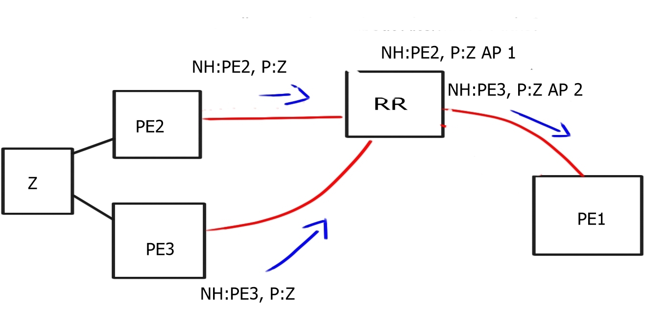
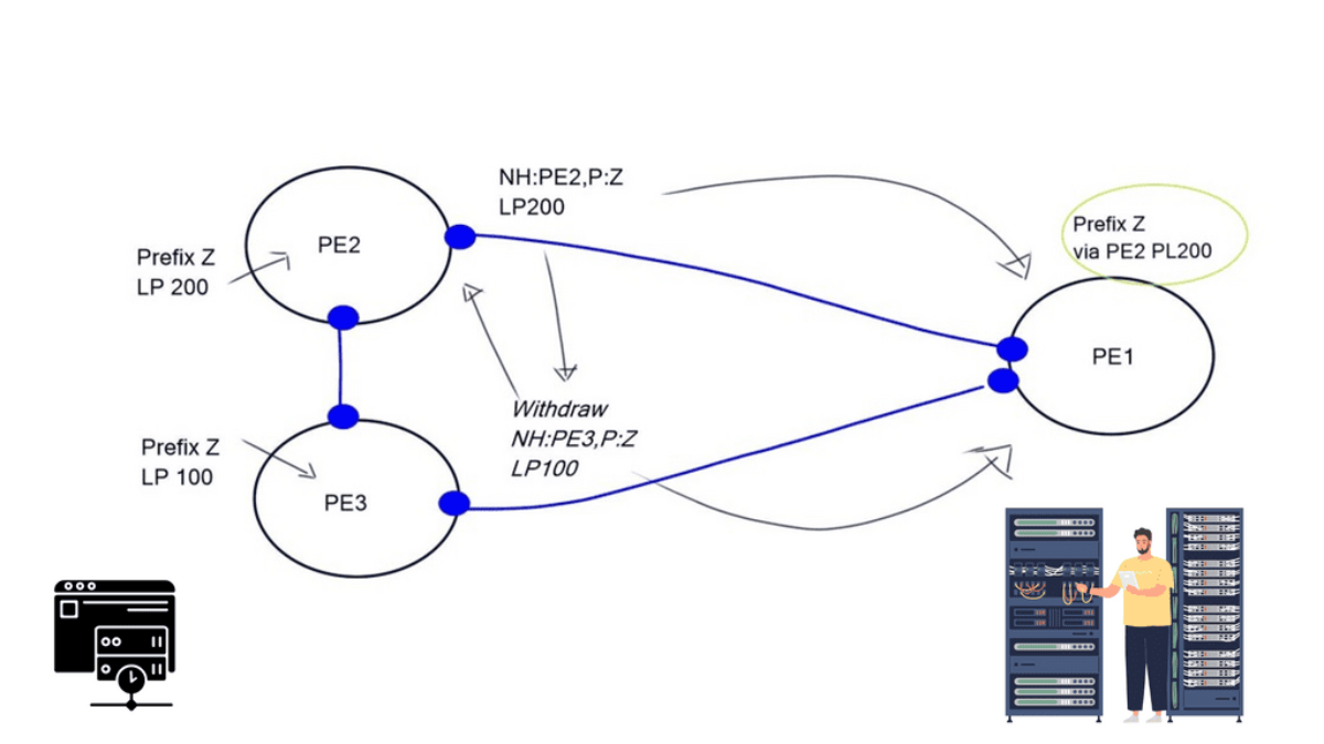
All transit providers want to protect the hot potato routing scheme for revenue reasons. Traffic consumes bandwidth and bandwidth costs money. Therefore, providers wish for traffic to leave their networks as soon as possible, aka hot potato routing. The problem is that when a route reflector receives two updates, it only sends one.
This is done by design for scalability reasons. BGP may also withdraw paths with lower policies (MED, Local Preference), resulting in only one NLRI announcement (diagram above). It was relevant, but you might want to send multiple routes for many reasons.
For example, faster convergence requires a primary and backup path and Multipath TCP use. Another issue is that the route reflector selects the best path based on its IGP and the route reflector’s shortest exit point. Route reflector deployments will choose the egress router closest to the RR, not its clients. It selects the best path based on the IGP metric computed from its IGP database and announces it to clients.
This is not optimum for egress traffic selection. As a result, traffic may travel longer paths to exit an AS. To combat this, most service providers create a full mesh of route reflectors in all regions, resulting in a route reflector in every PoP. However, an RR in every area is expensive if you have an extensive transit network.
BGP Multipath
There are several ways to get an RR or an ASBR to advertise more than one path:
- Different RD per prefix
- BGP Best External
- BGP Add Path
- BGP Optimal Route Reflection (ORR)
The recommended method for MPLS-VPN is to assign a different RD (VPN identifier) per prefix. If you are running Layer 3 VPN, you can assign different route distinguishers (RD) to the same prefix, resulting in different IP addresses NLRI. Then, the RR sees two different prefixes and will forward both.
RR does the best path on two different VPNv4/v6 NLRI. With BGP Best External, you tell the router not to withdraw an update, even if it’s not the best one. It provides the network with an external backup route.
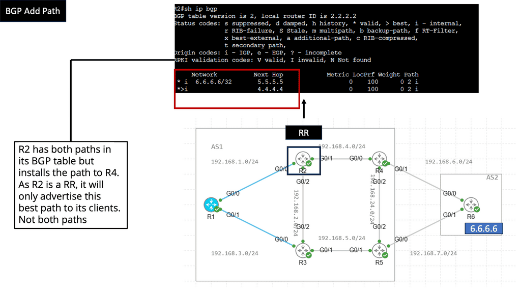
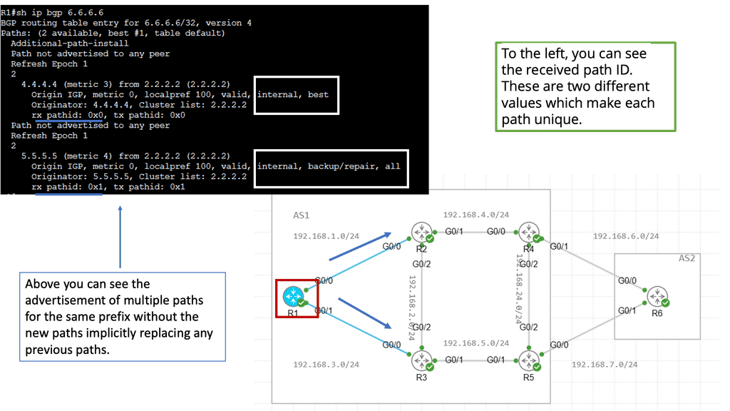
BGP Add path
The BGP Add path feature is a new BGP capability. It is an extension added to a BGP update where you can signal multiple paths to neighbors that must be negotiated at startup with all BGP neighbors. It’s the best method if you have a good memory and all nodes support it. All the information will be in the control plane, and you can still do hot potato routing. There are many add-path flavors, including Add-n-path, Add-all-path, and Add-all-multipath+backup.
BGP Optimal Route Reflection enables a virtual IGP location-style design. It builds multiple RIBs and computes the best path for each RIB. It would help if you influenced your IGP to mimic what it would be like in other network locations. It essentially overwrites the default IGP location placement of the route reflector, enabling clients to direct traffic to their closest exit point in hot potato routing deployments.
BGP Multipath is a powerful feature that enhances BGP-based networks’ scalability, performance, and resiliency. Enabling traffic load balancing across multiple paths helps optimize network utilization, prevent congestion, and improve overall reliability. However, careful planning, configuration, and monitoring are essential to ensure its successful implementation.