Application Traffic Steering: From Flow Awareness to Intelligent Path Selection
Modern networks must do more than discover a destination and forward packets toward it. They must support applications with different performance requirements, direct traffic across available paths, preserve security policy and respond when network conditions change. Application traffic steering brings these decisions together by matching traffic flows with the paths and services best suited to their requirements.
Voice traffic may require low latency and jitter. Video applications need sufficient bandwidth and stable delivery, while transactional services may depend on predictable response times and secure access. Sending every flow along the same path without considering these differences can waste capacity or degrade the user experience.
Traffic steering introduces an additional layer of decision-making. Depending on the architecture, the network can classify applications, evaluate path performance, apply routing policies, distribute requests across servers or direct selected flows through security services. The mechanisms differ, but the engineering objective is consistent: make forwarding and delivery decisions that align with application needs.
From application requirements to a steering decision
Why traditional routing is not the whole answer
Traditional IP routing primarily selects a forwarding next hop using destination prefixes and the routing information available to the router. Routing protocols can respond to topology changes and select among alternative routes, but ordinary destination-based forwarding does not automatically distinguish every application sharing the same destination.
Application traffic steering can introduce additional classification, policy and performance inputs. SD-WAN systems may select between WAN paths using measured latency, jitter or loss. Load balancers distribute requests among backend servers. Policy-Based Routing can override normal routing decisions for matching traffic, while programmable SDN architectures can install more granular forwarding rules.
These approaches are related, but they are not interchangeable. A steering design must identify which device makes the decision, which information it can observe and which forwarding actions its platform supports.
BGP Application Traffic Steering
Border Gateway Protocol (BGP) provides an important foundation for traffic engineering between autonomous systems and across interconnected networks. By exchanging reachability information and applying routing policy, BGP allows network engineers to influence which advertised route is selected and how traffic enters or leaves a network.
BGP-based steering is not the same as an application-aware SD-WAN engine. BGP generally operates on network-layer reachability and path attributes, rather than independently measuring every application's real-time experience. However, carefully designed BGP policies can support application delivery objectives when traffic is separated into suitable prefixes or routing domains, or when BGP works alongside more granular steering mechanisms.
Consider an enterprise network connected to two upstream providers. Both providers advertise reachability to a destination prefix. The enterprise can apply supported BGP policy to influence its preferred outbound route, while appropriately configured announcements and attributes can influence how remote networks select paths toward it.
The preferred path depends on routing policy, BGP attributes, reachability and the decision process at the relevant routers. Local preference can influence outbound path selection within an autonomous system; AS-path prepending may influence some remote networks' inbound route choices, but it is not a guarantee. BGP does not automatically select the lowest-latency application path.
BGP techniques explored in this article
Performance and security must work together
A path that appears optimal from a latency or bandwidth perspective may still be unsuitable if it violates a security policy, traverses an unavailable service or fails a forwarding check. Effective steering therefore combines performance objectives with reachability, security controls and operational constraints.
This is especially important when BGP is part of the solution. A route can be valid and selected by BGP without guaranteeing that the application will achieve its required response time. Engineers must distinguish routing reachability from end-to-end application health.
A routing decision determines where traffic can be forwarded. An application steering strategy determines which available path or service best satisfies the application's requirements, within the capabilities of the network and its configured policies.
What this learning journey covers
Continue through the article to examine how traffic is classified, how available paths are compared, how BGP policies influence route selection and how a steering decision can be tested against real forwarding and security constraints.
How Application Traffic Steering Works
Application traffic steering is the process of identifying a flow, evaluating its requirements and choosing an appropriate forwarding or application-handling decision. It brings policy into the path a request takes, rather than treating every flow as an identical destination lookup.
Start with the core model: classify traffic, evaluate policy, select an eligible path and verify the outcome. This foundation helps distinguish ordinary routing from policy-based routing, SD-WAN, load balancing and application-aware controls.
How Application Traffic Steering Works
Application traffic steering is the process of directing network traffic according to application requirements, network conditions and configured policy. Rather than treating every packet or connection identically, a steering system can identify relevant traffic, evaluate the available forwarding choices and apply an appropriate action.
The decision may happen at different points in the network. An edge router can apply Policy-Based Routing (PBR), an SD-WAN appliance can select a WAN path, a load balancer can choose a backend server, or a programmable network controller can install flow-specific forwarding rules. The mechanism depends on the problem being solved and the capabilities of the infrastructure.
The four stages of a steering decision
What information can influence the decision?
Steering decisions are only as good as the information available to the component making them. Some mechanisms rely primarily on packet headers and routing policy. Others incorporate application recognition, active probes, telemetry, user identity or the health of destination services.
Traffic and policy context
Source and destination prefixes, transport protocol, ports, routing attributes, access rules and application classification can determine which policy applies to a flow.
Path and service conditions
Depending on the platform, measured latency, jitter, packet loss, bandwidth, link state and backend health can help determine which available path or service is suitable.
Routing establishes reachability and selects routes according to the routing information and decision rules in use. Application traffic steering adds classification or policy objectives that influence how selected traffic is handled. A routing protocol does not automatically provide application awareness or real-time performance measurement.
Three common steering approaches
- Policy-Based Routing: Matches defined traffic criteria and directs matching packets through a configured next hop or forwarding action, where supported.
- SD-WAN path selection: Can use link measurements and application policies to choose between available WAN transports.
- Load balancing: Distributes connections or requests across eligible servers or service endpoints, often using health checks and a configured selection algorithm.
BGP can also influence traffic paths by exchanging reachability and applying attributes and routing policy. For example, local preference can influence outbound route selection within an autonomous system, while AS-path prepending may affect some remote networks' inbound choices. These techniques operate at the routing-policy level and do not, by themselves, guarantee the lowest-latency path for a particular application.
Example: steering traffic away from a degraded link
Imagine a branch office with two WAN connections. Both links are available, but the primary connection begins experiencing increased packet loss. A steering system with suitable measurement and policy capabilities may direct eligible application traffic to the secondary connection. When the primary link meets the configured recovery conditions, the system may return traffic to it.
Observe: The primary link's measured loss exceeds the
configured threshold.
Evaluate: The secondary link is available and satisfies
the applicable policy.
Steer: Eligible traffic is directed through the
secondary link.
Verify: Monitoring confirms the forwarding change and
checks whether application performance improves.
Design considerations
- Define the objective. Decide whether the priority is availability, latency, loss, cost, security or a combination of factors.
- Understand the control point. Identify which router, SD-WAN appliance, controller or load balancer can enforce the decision.
- Check the return path. Asymmetric routing, stateful firewalls and session persistence can affect whether a change works correctly.
- Validate the outcome. A selected route or link is not proof that application performance has improved; measure the result.
Application traffic steering connects traffic classification, policy, path selection and verification. Understanding where each decision is made is the first step toward choosing the right mechanism, whether that is PBR, SD-WAN, load balancing, BGP policy or programmable flow-level control.
Classify. Decide. Steer. Verify.
HTTPS request
Policy-Based Routing: Classifying Traffic and Choosing a Path
Policy-Based Routing (PBR) allows selected traffic to follow a policy-defined forwarding decision rather than relying exclusively on the normal destination-based route lookup. Rules may match supported attributes such as source address, destination address, protocol or transport ports.
PBR is useful when different traffic classes need different next hops or handling. Its effectiveness depends on correct match conditions, reachable next hops, suitable fallback behaviour and careful validation of both forward and return traffic.
Policy-Based Routing: Classifying Traffic and Choosing a Path
Policy-Based Routing (PBR) allows a network device to make forwarding decisions using configured traffic-matching rules rather than relying exclusively on the destination-based route lookup. It can direct selected traffic toward a particular next hop or interface when the platform, policy and forwarding design support that action.
PBR is useful when different traffic classes need different treatment. For example, an organisation might direct traffic from a particular department through a security appliance, send selected application traffic over a dedicated WAN connection, or route traffic from a specific subnet toward a service network.
How a PBR decision is made
What can a policy match?
The exact matching options depend on the vendor and platform. Common implementations use access control lists or equivalent classifiers to identify traffic using network and transport-layer fields.
Match source or destination IP prefixes to apply different forwarding policies to users, subnets or destination networks.
Where supported, distinguish traffic by protocol and port, such as selected TCP or UDP flows.
Use configured classifiers, markings or other supported criteria to associate traffic with a forwarding policy.
Use platform-supported tracking or failover mechanisms where available so a policy does not blindly depend on an unusable next hop.
Example: sending selected traffic through a preferred path
Consider a branch router connected to two upstream paths. A defined traffic class should use the preferred path, while other traffic continues to use the normal routing table. PBR can implement this separation when the router supports the required matching and forwarding actions.
This is a conceptual flow, not vendor-specific configuration. The actual processing order, supported actions and fallback behaviour must be confirmed for the router and software release in use.
PBR versus ordinary destination-based routing
The device normally consults its forwarding information to select the best matching destination prefix and corresponding next hop. The result is primarily determined by destination reachability and the routing information installed in the forwarding table.
Matching traffic can receive a policy-defined forwarding treatment that differs from the normal destination-based choice. Traffic that does not match the policy generally follows the platform's configured normal routing behaviour.
PBR does not automatically discover the best-performing path. A configured policy may select a next hop even when that path is congested or unavailable unless suitable tracking, failover and verification mechanisms are configured.
Where PBR fits in application traffic steering
PBR is particularly useful when the steering requirement can be expressed as a clear rule and enforced at a suitable network device. It can provide deterministic traffic handling, but it is not inherently equivalent to deep application recognition or continuous performance-aware path selection.
- Use PBR when defined traffic matches must use a particular supported forwarding path.
- Consider SD-WAN when path decisions need to incorporate measured WAN performance and application policies.
- Consider load balancing when the decision is which backend server or service endpoint should receive a request.
- Consider BGP policy when the objective is to influence route selection and reachability across BGP-controlled networks.
PBR turns a traffic-matching rule into a forwarding decision. Successful deployment requires precise match criteria, a valid next hop, a defined fallback strategy and operational checks that confirm traffic reaches its intended destination.
Policy-Based Routing: Match the Flow, Choose the Path
Preferred for selected classes
Alternate policy path
SD-WAN and Performance-Based Path Selection
SD-WAN can combine centralised policy with measurements from available network paths. Depending on the platform, information such as latency, jitter, packet loss and link health can help determine whether a path is suitable for a particular application or traffic class.
The key difference from conventional routing is the use of application requirements and path-quality information in steering decisions. Performance-based steering still needs thresholds, failover rules and recovery logic to avoid unstable path changes.
SD-WAN and Performance-Based Path Selection
Software-Defined Wide Area Networking (SD-WAN) can extend traffic steering beyond static path preferences by combining application policies with information about available WAN connections. Depending on the implementation, an SD-WAN edge can evaluate link measurements, identify application traffic and select an eligible path according to configured service requirements.
A branch office might have broadband, business fibre and an MPLS connection. These links can differ in cost, capacity, latency and reliability. Instead of treating one connection as universally best, an SD-WAN policy can determine which transport is suitable for each traffic class and respond when conditions change.
Which measurements matter?
Measures the time taken for traffic to travel between measurement points. Lower latency can benefit interactive applications such as voice, remote desktops and transactional systems.
Describes variation in packet delay. Unstable delay can affect real-time audio and video even when average latency appears acceptable.
Indicates packets that fail to reach the measurement destination. Loss can degrade voice and video and trigger retransmissions for applications using reliable transport protocols.
Helps determine whether a path can support the expected traffic demand. Capacity estimates must be interpreted alongside congestion, shaping and competing traffic.
From telemetry to a forwarding action
Example: choosing between two WAN paths
Imagine that a branch uses two WAN transports. The primary link normally carries voice and business application traffic, but its measured loss increases. The secondary link remains within the policy's acceptable performance limits. An SD-WAN implementation may steer the affected application traffic to the secondary path, provided the configured policy and platform support that behaviour.
The connection is still reachable, but its measured quality no longer satisfies the application's configured requirements.
The alternative connection is eligible for the affected traffic, so the steering policy may prefer it until conditions change.
The key point is that link availability and link suitability are different questions. A link can remain operational while its measured performance falls outside the requirements of a particular application.
Different applications need different policies
Prioritise acceptable latency, jitter and loss. A high-capacity path may still be unsuitable if delay variation is excessive.
Consider available capacity, transfer duration and cost. These applications may tolerate more delay than interactive services.
Define acceptable performance and availability requirements, with clear rules for alternate paths and recovery.
Apply appropriate access, capacity and cost policies without automatically giving every flow the same path preference.
Failover is only part of the design
Steering traffic away from a degraded connection is useful, but the policy must also define what happens when the preferred path recovers. Without suitable thresholds, hold-down periods or other stability controls, repeated changes can cause unnecessary path switching. The precise controls available depend on the platform.
- Define thresholds: Specify which measured conditions make a path acceptable or unsuitable.
- Plan recovery: Determine when traffic should return to the preferred path after performance improves.
- Check capacity: Ensure the alternate path can handle the traffic it may receive during degradation or failure.
- Verify application health: Confirm that the path change actually improves the user experience.
SD-WAN can make policy-driven path choices using application classification and measured transport performance. BGP exchanges reachability and applies routing policy to select routes. They can complement each other, but BGP alone does not provide the same application-level measurement and steering behaviour as a performance-aware SD-WAN system.
Key takeaway
Performance-based steering connects path measurement to application policy. It can help networks respond to changing WAN conditions, but effective deployment requires realistic thresholds, stable failover behaviour, sufficient backup capacity and end-to-end verification.
SD-WAN Performance-Based Path Selection
Watch an application flow get matched to a policy, evaluated against live link conditions, and forwarded over a selected WAN path.
Choose an application profile, then step through the path-selection process.
Select an application and step forward to begin.
Load Balancing: Steering Requests to Healthy Services
Load balancing distributes incoming requests or connections across a group of service instances. Instead of sending every request to one endpoint, a load balancer can select a backend according to its configured algorithm, health status and other supported criteria.
Layer 4 load balancing generally uses transport-level connection information, while Layer 7 balancing can make decisions using application protocol details. Both can improve availability and resource utilisation, but neither removes the need for health checks, capacity planning and session-handling decisions.
Load Balancing: Steering Requests to Healthy Services
Load balancing distributes client connections or application requests across multiple servers or service endpoints. Rather than allowing every request to depend on a single backend, a load balancer selects an eligible destination according to its configured algorithm, health information and any applicable session or routing policy.
This is a different steering problem from selecting a WAN path or choosing a BGP route. Load balancing focuses on where a request or connection should be delivered within an application service. It can improve capacity utilisation and availability, but the result depends on how backend health, session state and application behaviour are handled.
A typical application delivery architecture
The load balancer receives a request or connection, applies its selection logic and directs it to a backend that is eligible to serve the traffic. The exact forwarding model depends on whether the implementation operates at Layer 4, Layer 7 or another supported service-delivery layer.
Layer 4 and Layer 7 load balancing
Uses transport and network connection information, commonly including IP addresses, protocol and TCP or UDP ports. It can distribute connections without needing to interpret the full application request.
Can make decisions using application-layer information such as HTTP hostnames, URL paths, headers or other supported request attributes. This enables more granular application delivery policies.
Layer 7 visibility can support more detailed routing decisions, but it introduces additional considerations, including TLS termination, certificate handling, request parsing and the privacy of application data. The chosen design should match the requirements of the service.
Common backend selection methods
Distributes new selections sequentially across eligible backend servers. It is simple, but does not inherently account for different server capacities or current workloads.
Assigns different selection weights to backends. A server with a higher configured weight can receive a larger share of selections, depending on the algorithm.
Selects a backend based on its active connection count, where supported. This can help distribute connection load but may not accurately represent the processing cost of every request.
Uses a key such as a client address or request attribute to select a backend. Depending on the method, this can help maintain consistency for related requests.
Health checks: avoid sending traffic to failed backends
A backend can remain reachable at the IP layer while its application is unable to serve requests correctly. Load balancers therefore commonly use health checks to determine whether a destination should remain in the eligible backend pool.
- Connectivity checks: Verify that a supported network or transport endpoint responds.
- Application checks: Request a health endpoint or test a service-specific condition when configured.
- Pool membership: Remove unhealthy destinations from new selections and restore them according to the configured recovery rules.
- Capacity awareness: Consider whether the remaining healthy servers can handle the additional traffic.
A successful health check confirms only the conditions that it actually tests. A basic TCP check may pass while a database dependency, login workflow or critical application function is failing. Health checks should be designed to reflect the service's real operational needs.
Session persistence and state
Some applications store session state locally on a particular server. If successive requests from the same user are sent to different backends, the application may lose access to that state unless the architecture supports shared sessions or another state-management mechanism.
Session persistence, sometimes called stickiness, can help keep related requests associated with a backend. However, it can also create uneven load distribution or reduce flexibility during a failure. Shared session storage and stateless application design can reduce dependence on persistent backend selection.
Load balancing versus network traffic steering
Chooses how traffic traverses the network, for example by selecting a WAN transport, applying PBR or influencing route selection through BGP policy.
Chooses which eligible server or service endpoint receives a request or connection. It operates at the application delivery layer rather than simply selecting an IP route.
These mechanisms can work together. Routing and SD-WAN determine how traffic reaches the application delivery infrastructure, while the load balancer selects a backend. A successful end-to-end design needs both layers to be reachable and correctly configured.
Design checks before deployment
- Capacity: Confirm that the load balancer and healthy backends can support expected traffic and failure scenarios.
- Protocol behaviour: Check TLS termination, connection reuse, timeouts and supported application protocols.
- Failure handling: Define how unhealthy backends are detected, excluded and returned to service.
- Observability: Monitor backend health, request errors, response times and distribution across the server pool.
Load balancing steers requests or connections across eligible application backends. Effective application delivery combines an appropriate selection algorithm, meaningful health checks, session-state planning and monitoring. It complements network-level steering but solves a different part of the delivery problem.
Load Balancing and Application Delivery
Send application requests through a load balancer, observe server selection, and test how health checks change traffic distribution.
Select a balancing algorithm, then send a request to see which healthy server receives it.
Ready to simulate application requests.
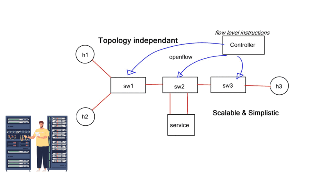
SDN, OpenFlow and Flow-Level Traffic Steering
Software-Defined Networking introduces programmable approaches to network control. In compatible architectures, a controller can coordinate forwarding policies and install rules that classify selected packets and specify how those packets should be processed.
OpenFlow is one example of a protocol used to manage flow-table entries on supported switches. This section explores match/action logic, rule priorities and installation strategies, along with the operational checks needed to ensure that programmed forwarding matches the intended policy.
SDN, OpenFlow and Flow-Level Traffic Steering
Software-Defined Networking (SDN) introduces a programmable approach to network control. Instead of configuring every forwarding decision only through individual device interfaces, an SDN architecture can use a controller or network application to define policies and coordinate forwarding behaviour across supported network devices.
This approach can support more granular steering than conventional destination-based routing alone. Depending on the platform and forwarding technology, traffic can be classified using fields such as source and destination addresses, protocol and transport ports, then handled using rules that specify the permitted forwarding actions.
Separating network control from packet forwarding
Computes or coordinates forwarding policies, maintains a view of relevant network state and communicates supported rules to network devices through the applicable control interface.
Processes packets using installed forwarding entries, match criteria and supported actions. The device performs the actual packet handling at forwarding time.
The separation is conceptual rather than absolute. Real networks still require mechanisms for topology discovery, reachability, failure handling, rule installation and coordination between control and forwarding components. SDN platforms differ in how they implement these functions.
How a programmable steering rule is applied
OpenFlow and match/action forwarding
OpenFlow is a protocol historically associated with SDN that allows a controller to communicate with compatible switches and manage supported flow-table entries. An entry can contain match fields, priority, counters and instructions or actions that determine how matching packets are processed.
Depending on the OpenFlow version and switch capabilities, actions may include forwarding to a port, dropping a packet, modifying supported header fields or directing processing to another table. The precise capabilities are version- and implementation-dependent.
This is an illustrative rule, not executable OpenFlow syntax. It shows how selected traffic can be distinguished from other packets and associated with a forwarding action supported by the device.
Why rule priority and table processing matter
A programmable switch may contain many flow entries. Multiple entries can potentially match the same packet, so priority and table-processing rules determine which entry applies and how processing continues. Broad rules can unintentionally override more specific policies if they are installed with inappropriate priorities or instructions.
- Specificity: Ensure that intended traffic matches the correct entry rather than an unrelated broad rule.
- Priority: Use a deliberate priority strategy for overlapping match conditions.
- Fallback: Define the intended behaviour when no specific entry matches.
- Lifecycle: Consider timeouts, stale entries, updates and cleanup when policies change.
Reactive and proactive rule installation
A device or controller interaction triggered by traffic can lead to a rule being installed after the relevant flow is first encountered. This can provide flexibility but may introduce initial setup delay and control-plane workload.
Rules are installed before the associated traffic arrives. This can reduce first-packet setup delays, provided the required policies, topology information and forwarding entries are already available.
Where programmable flow steering is useful
Apply distinct forwarding policies to selected traffic classes or network segments, subject to the platform's match and action support.
Direct eligible traffic through a firewall, inspection system or other service before it reaches its destination.
Select a supported forwarding path based on controller policy and network state, rather than relying solely on the normal forwarding choice for the destination.
Test traffic classification and forwarding changes in a controlled lab before considering a production deployment.
A controller can only install actions supported by the target devices, and the resulting path must still be valid. Rule conflicts, stale state, control-channel failures and incomplete topology information can affect traffic delivery. Validate both the controller's policy and the forwarding behaviour of the devices.
SDN flow rules versus BGP policy
BGP primarily exchanges reachability information and applies routing attributes and policy to select routes. Programmable flow steering can operate at a finer granularity when the forwarding platform supports the required packet matches and actions.
The two approaches can coexist. BGP can provide reachability between routing domains, while an SDN-controlled data plane applies more specific forwarding rules within a network. Their responsibilities should be clearly separated to avoid conflicting decisions or unexpected forwarding behaviour.
Engineering checks
- Device compatibility: Confirm supported protocols, match fields, actions, table capacity and controller integration.
- Failure behaviour: Decide what happens when the controller or its communication channel becomes unavailable.
- Rule consistency: Validate policy updates and ensure that partially installed rules do not create unintended traffic paths.
- Security: Restrict controller access and protect the interfaces used to program forwarding behaviour.
- Observability: Inspect flow counters, device state, packet paths and application outcomes.
SDN and OpenFlow illustrate how programmable forwarding can turn centrally defined policy into flow-level actions. The benefits depend on device support, sound rule design, reliable control mechanisms and verification that the installed forwarding behaviour matches the intended policy.
SDN, OpenFlow and Flow-Level Steering
Install a flow rule, send a packet through a programmable switch, and inspect how match fields determine the forwarding action.
| Priority | Match fields | Action | Packets | State |
|---|---|---|---|---|
| 200 | UDP · DSCP EF | Output: Port 2 | 0 | Installed |
| 100 | TCP · Destination 443 | Output: Port 1 | 0 | Installed |
Choose a packet profile and send a test packet. The switch checks installed rules in priority order.
Default demonstration rules are available.
Service Insertion and Service Function Chaining
Some application flows need to pass through security or inspection functions before reaching their destination. Service insertion directs selected traffic through a required service, while Service Function Chaining defines a logical sequence of functions for a particular traffic class or service.
Building a reliable chain involves more than drawing a path through appliances. Engineers must consider service health, return-path behaviour, capacity, latency, failure handling and the policy requirements that determine which traffic must traverse each function.
Service Insertion and Service Function Chaining
Application traffic does not always travel directly from source to destination. Some flows must pass through security, inspection or optimisation services before they reach their target. Service insertion steers selected traffic through these functions, while Service Function Chaining (SFC) defines an intended sequence of functions for a traffic class or service.
For example, traffic entering an enterprise application may need to pass through a firewall, an intrusion prevention system and a traffic monitor. The steering system must identify the relevant traffic, select the required service path and preserve the intended forwarding behaviour throughout the chain.
What is a service function chain?
This diagram illustrates one possible chain. A real deployment may use different functions, may bypass selected services for certain traffic classes, and must account for return traffic and the capabilities of the services and forwarding infrastructure.
Common service functions
Applies access-control policy to permit or deny traffic according to defined rules and connection state.
Examines eligible traffic for suspicious patterns or known threats and applies configured prevention actions.
Mediates selected application connections, potentially enforcing application policy or providing protocol-aware processing.
Collects or analyses traffic information for troubleshooting, performance measurement and operational visibility.
How service-aware steering works
This is a conceptual workflow rather than a protocol-specific implementation. The exact sequence depends on the network architecture, steering mechanism and service-chain design.
Policy-based service selection
Not every application flow needs the same treatment. A steering policy can associate traffic classes with different service requirements. The classification method may use network-layer fields, transport-layer information, application identity or metadata supplied by a trusted policy system, depending on the platform.
Send eligible traffic through firewall inspection before forwarding it to an internal application.
Apply a separate access policy and direct traffic through the appropriate security controls.
Require additional inspection or monitoring where the policy and applicable privacy requirements permit it.
Use a shorter approved path when policy allows, avoiding unnecessary service processing and additional latency.
Bypassing a service can reduce latency and processing overhead, but it may also remove a required security or compliance control. Steering decisions must respect the intended service policy, not simply choose the route with the fewest hops.
Ways to implement service insertion
Match selected traffic and direct it toward a service next hop or inspection path. The design must account for routing reachability, next-hop availability and return traffic.
Use controller-managed forwarding rules to steer supported traffic through selected service points, subject to device capabilities.
Define a logical sequence of service functions and use a compatible forwarding architecture to guide traffic through that sequence.
Insert an application-aware intermediary that can enforce policy, inspect supported protocols or select an appropriate backend.
Operational challenges to design for
- Service availability: Define what happens if a required firewall or inspection service becomes unavailable. Fail-open and fail-closed behaviour have different security and availability consequences.
- Return-path symmetry: Stateful services may require both directions of a connection to traverse the same service instance or a coordinated cluster.
- Capacity and latency: Each service adds processing overhead and may become a bottleneck. Estimate aggregate throughput, connection scale and expected delay.
- Loop prevention: Ensure that traffic cannot repeatedly re-enter the same service chain because of incorrect forwarding rules.
- Encapsulation and MTU: If the architecture adds encapsulation, validate path MTU and account for the extra headers.
- Policy consistency: Make sure changes to classification or chain definitions are reflected safely across the relevant devices.
Example: investigating an application delay
Users report that an internal application has become slow. The network path includes a firewall, an inspection service and the application gateway.
The aim is to identify which part of the chain contributes to the delay. Removing a service without confirming its security role is not a sound troubleshooting shortcut.
Service chaining versus ordinary routing
Ordinary routing generally selects a next hop toward a destination according to the routing table and associated policy. Service chaining adds another requirement: eligible traffic must visit specified functions before continuing toward its destination.
BGP can provide reachability to service networks or destinations, but BGP alone does not define a complete application service chain. Additional policy, forwarding rules or service-chain mechanisms are needed to enforce the required sequence.
Service insertion makes traffic steering aware of the network services a flow must traverse. A successful design combines correct classification, a deliberate service sequence, reliable forwarding, health handling and verification that security and application requirements remain satisfied.
Service Insertion and Service Function Chaining
Steer application traffic through a defined sequence of security and visibility services before it reaches the destination.
Select a chain profile and process the flow one stage at a time, or run the complete chain.
Ready to process an application flow.
Identity-Aware Traffic Steering
Traffic decisions can use more than IP addresses and ports. An application may also evaluate authenticated user identity, workload identity, roles and trusted policy signals to determine which resources or services a request is permitted to access.
This section connects application-level policy to traffic handling through a Node.js example. It also explains the boundary between choosing an application backend and changing the network forwarding path, plus the validation and enforcement needed to make identity-aware decisions secure.
Identity-Aware Traffic Steering
Traditional network policies commonly classify traffic using addresses, protocols, ports and other packet attributes. Modern application architectures can add another dimension: identity. An application may use authenticated user identity, workload identity or a trusted policy decision to determine which service, resource or application path a request is allowed to access.
Identity-aware steering connects application context to policy enforcement. For example, a request from an authorised employee might be directed to an internal application service, while a request without the required permissions is denied or sent through an additional verification step.
Identity-aware application routing is not automatically the same as network-layer path selection. An application gateway may choose a backend or reject a request without changing the underlying IP route. Network forwarding changes require a compatible network policy or steering mechanism.
From identity to an application decision
What information can inform steering?
A verified user identity or group membership can help determine whether a request is permitted to access a protected application.
A service-to-service request can be evaluated using the identity of the calling workload, rather than trusting its IP address alone.
The requested resource and operation can determine which application handler, backend or access policy should apply.
A trusted access system may provide policy outcomes based on approved context, subject to the organisation's security design.
Example: a Node.js application gateway
Consider a Node.js service that receives an authenticated request and determines which application endpoint the caller may use. The application should verify the authentication evidence and then make an explicit authorisation decision. It should not treat a client-supplied role, username or HTTP header as proof of identity.
The diagram describes a control flow rather than a complete, production-ready authentication implementation. Token verification must use a trusted identity configuration and suitable libraries.
Illustrative Node.js decision function
The following small example demonstrates the policy decision after authentication has already been performed by a trusted middleware or identity integration. It is not a substitute for verifying credentials.
In this example, the function receives a principal object created by trusted authentication middleware. It checks an allowlisted set of roles and returns a service selection or denial. A real application must also enforce the returned decision, validate the principal's provenance and apply resource-specific authorisation.
Returning a service name does not itself secure a request. The application must ensure that the selected service is actually used, that unauthorised callers cannot bypass the gateway and that each downstream service applies its own required access controls.
Application steering versus network steering
A gateway or application can direct a permitted request to a service, API version or backend pool. The underlying network still forwards packets according to its own routing and forwarding rules.
A network policy, SDN controller or compatible forwarding system changes how eligible packets traverse the network. It needs an appropriate way to map trusted identity or policy context to traffic.
How identity can connect to network policy
In a larger architecture, an identity-aware application or policy service may communicate a decision to an enforcement point. Depending on the environment, enforcement could occur at an API gateway, service mesh proxy, firewall, network access control system or programmable network controller.
- Establish a trusted mapping: Define how an authenticated identity or workload maps to a policy and the traffic it governs.
- Use an appropriate enforcement point: Apply the decision where the relevant request or traffic can actually be controlled.
- Limit policy scope: Avoid broad network changes when an application-level allow or deny decision is sufficient.
- Handle policy changes: Consider token expiry, revoked permissions, stale rules and the time needed to distribute updates.
- Maintain observability: Correlate application decisions with network events using suitable identifiers while minimising sensitive information in logs.
Security and operational considerations
Validate signature, issuer, audience, expiry and other required claims. Never trust decoded token contents without verifying the token.
Grant only the permissions required for the specific resource and operation. A general role should not automatically imply unrestricted access.
Remove or overwrite externally supplied identity headers at a trusted gateway before passing identity context to downstream services.
Define what happens when the identity provider or policy service is unavailable. Avoid silently treating an unknown identity as authorised.
When is identity-aware steering useful?
- Multi-tenant platforms: Direct authorised requests to the correct tenant service while preventing cross-tenant access.
- Internal APIs: Apply different permissions to operations, users and service identities.
- Zero-trust architectures: Make access decisions based on verified identity and policy rather than relying on network location as the sole trust signal.
- Controlled application migration: Direct eligible requests to an approved service version or backend after authorisation.
Identity-aware traffic steering brings authenticated identity and application policy into request handling. Node.js can demonstrate application-level service selection, while broader network steering requires a trusted integration between identity, policy and the appropriate forwarding enforcement point.
Identity-Aware Traffic Steering
Use identity, device posture and application context to determine which services a user can reach and how their traffic is handled.
Choose an identity, application and device posture. Then evaluate the request to see how policy changes the traffic path.
Waiting for an access request.
Conclusion: From Traffic Forwarding to Intent-Based Steering
Application traffic steering is about more than finding a route from one network to another. It is about making an informed forwarding decision based on the application, the user, the current network conditions, security requirements and the destination service.
Traditional routing provides the underlying reachability, while technologies such as policy-based routing, SD-WAN, load balancing, software-defined networking and service function chaining add different ways to influence how traffic travels. Identity-aware policies extend this approach by considering who is requesting access, whether the device is trusted and which application the user is permitted to reach.
Classify the traffic, evaluate the relevant policy, select an appropriate path, and verify the outcome. Effective steering must balance application performance, availability, security and operational simplicity rather than optimise one factor in isolation.
Where does BGP fit into application traffic steering?
Border Gateway Protocol (BGP) supplies routing information and path-selection mechanisms that can support traffic-engineering objectives. Local preference can influence outbound path selection within an autonomous system, AS-path prepending can influence how some external networks compare routes, and carefully designed more-specific advertisements can affect inbound traffic patterns. These mechanisms have different scopes and limitations: they do not replace application-aware policy, and their effect depends on routing configuration and the behaviour of other networks.
In a real deployment, the best design is rarely a single technology. Routing, application delivery, security controls and identity policy often work together. The challenge is to define clear responsibilities between these layers, avoid conflicting policies, and ensure that a steering decision remains observable and supportable when conditions change.
Final takeaway: Good traffic steering is deliberate, measurable and policy-driven. The goal is not simply to move packets along a different path; it is to deliver the required application experience through a path that meets the organisation's performance, availability and security objectives.