
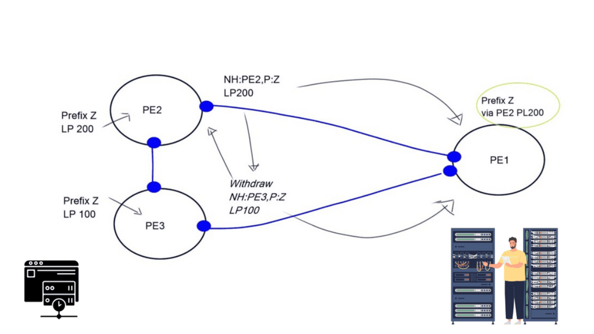
BGP Multipath

BGP Multipath

NETWORK INSIGHT · BGP ENGINEERING GUIDE
BGP Multipath: From Route Selection to Forwarding

A BGP router can learn several routes to the same destination, select a preferred path, and still install multiple next hops for forwarding. Understanding how these decisions interact is essential when designing resilient, load-sharing networks and troubleshooting unexpected traffic behaviour.

BGP Multipath allows a router to install multiple eligible paths for a prefix, subject to its configuration, path-selection rules and platform capabilities. Instead of relying on a single forwarding next hop, the router can use a set of next hops to distribute traffic and maintain forwarding options when a path becomes unavailable.

The important distinction is that routes learned by BGP are not automatically routes installed in the forwarding table. A route may be present in the BGP table yet fail a multipath eligibility check. Even when several paths are installed, the actual traffic distribution depends on the forwarding implementation and its hashing behaviour.

The engineering question

If a router learns two or more paths to the same prefix, what determines which next hops reach the FIB, how is traffic distributed across them, and what happens when one path fails?

01 · SEE

Understand the path set

Follow candidate routes from BGP selection through multipath eligibility to the next hops installed in the forwarding table.

02 · OBSERVE

Verify traffic distribution

Compare installed paths with forwarding state, interface counters, traffic demand and path characteristics.

03 · INVESTIGATE

Find the missing path

Use routing evidence to identify why a candidate path is excluded and validate the result after a change or failure.

This guide combines routing concepts with interactive engineering labs. You will examine candidate paths, change the permitted multipath count, investigate a missing forwarding next hop, and explore how Route Reflectors and BGP Add-Path affect the visibility and advertisement of alternative routes.

Engineering guide · Navigation

4 investigation stages

BGP Multipath: Engineering Navigation

Follow the route from BGP selection to real forwarding behaviour. Each stage builds on the previous one, moving from architecture and visibility to fault isolation and verified recovery.

SECTION 01 · SEE THE FORWARDING PATH

When Does a BGP Route Become a Forwarding Next Hop?

Learning multiple routes does not mean installing every route. A router evaluates candidate paths, applies its BGP decision process and checks which alternatives qualify for multipath forwarding. Follow the decision chain below.

STAGE 01 Learn routes Receive candidate paths from BGP peers.
STAGE 02 Evaluate paths Compare policy attributes and route eligibility.
STAGE 03 Check multipath Apply maximum-paths and implementation-specific rules.
STAGE 04 Install next hops Program eligible paths into forwarding, if installation succeeds.
Engineering question: Which candidate paths qualify for the multipath set, and how can you prove that their next hops were actually installed in the FIB?

Section 1 — From BGP Paths to Forwarding

BGP multipath is the ability to install multiple eligible routes to the same destination into a router's forwarding state, rather than relying on a single next hop. It can improve link utilisation and provide additional forwarding options, but only when the routes satisfy the platform's multipath rules and the forwarding hardware can use them.

The important engineering distinction is between routes BGP knows about and next hops the router actually uses to forward packets. A router may learn several paths for a prefix yet select only one for installation. Seeing multiple paths in a BGP table is therefore not proof that multipath forwarding is active.

Engineering question: For a destination prefix, which candidate paths qualify for multipath, which next hops are installed in the forwarding information base (FIB), and what evidence proves packets can use those next hops?

1.1 The path from route learning to packet forwarding

BGP receives route advertisements from peers and evaluates the attributes and policies associated with each path. The routing process then determines the eligible route or routes. If multipath is configured and the relevant eligibility conditions are met, the router may install multiple next hops for the same prefix. The data plane uses the installed forwarding state to direct packets.

Stage 01 Learn routes

Receive BGP UPDATEs and maintain paths learned from peers.

Stage 02 Evaluate paths

Apply policy, compare attributes and assess route eligibility.

Stage 03 Check multipath

Determine whether additional paths satisfy configured rules.

Stage 04 Install next hops

Program usable forwarding entries and verify the resulting FIB.

These stages describe the conceptual workflow; exact implementation details differ between vendors and operating systems. Some platforms expose a separate multipath set, while others present the selected route and additional forwarding next hops through different commands.

1.2 BGP RIB versus FIB: two different views

The routing information base (RIB) represents route information maintained by the control plane. The forwarding information base (FIB) contains the entries used by the forwarding plane. The two are related, but they answer different operational questions.

Evidence source What it tells you What it does not prove alone
BGP route table Which BGP paths are known, their attributes and their selection status. That every visible path is installed for forwarding.
Routing table / RIB Which route or routes the routing process has selected for the destination. That all intended next hops are programmed and usable in hardware.
Forwarding table / FIB Which next-hop entries the forwarding plane uses for matching packets. That traffic is distributed evenly or that every path is healthy under load.
Interface and traffic counters Whether interfaces carry traffic and how utilisation changes. That BGP multipath is the only cause of the observed traffic pattern.

1.3 What makes a path eligible for multipath?

Enabling a maximum-paths setting does not mean that any route to the same prefix can be installed alongside the current best path. The router must still apply its route-selection process and its implementation-specific multipath criteria. Those criteria can include path attributes, peer type, next-hop reachability, routing policy and other platform-specific constraints.

Best-path selection and multipath eligibility are related, but not identical

BGP first evaluates routes according to its decision process. Multipath then permits additional paths that satisfy the implementation's requirements to be installed alongside the selected path. Depending on the platform and configuration, some attributes that matter to best-path selection may need to match or meet specific conditions for multipath. Do not assume identical requirements across vendors.

Path attributes

Compare attributes such as Local Preference, AS_PATH, origin and MED where relevant to the platform's multipath rules.

Next-hop reachability

Verify that each candidate next hop resolves through the routing table and has a usable forwarding path.

Configuration and limits

Check the applicable maximum-paths command, address family, peer type, policy and platform limits.

1.4 Configuring multipath: verify the scope, not just the command

Many BGP implementations provide a command such as maximum-paths to control how many eligible paths can be installed. The precise command, supported path types and default behaviour depend on the vendor, software release and address family. eBGP and iBGP multipath may use separate configuration.

Treat the following as an illustrative configuration pattern, not a universal command sequence:

Illustrative BGP configuration router bgp 65001 address-family ipv4 unicast maximum-paths 2

Before applying configuration, confirm the syntax and placement in your platform's documentation. After making a change, verify the operational result in both the routing table and the FIB. A configured limit of two paths is a ceiling, not a guarantee that two paths will qualify.

1.5 Worked example: three candidate paths, two installed next hops

Consider router R1 learning prefix 203.0.113.0/24 through three candidate paths. Assume Paths A and B meet the configured multipath criteria, while Path C does not. In this example, the router installs two next hops for the destination.

Candidate Control-plane observation Forwarding result
Path A Selected best path and eligible for multipath. Installed
Path B Meets the configured additional-path eligibility rules. Installed
Path C Visible as a candidate but fails a required eligibility condition in this scenario. Not installed

The router can now forward matching traffic using the installed next-hop set. How traffic is divided depends on the forwarding platform, hashing algorithm, flow characteristics and configuration. Two installed next hops do not guarantee a 50/50 traffic split, and packet ordering or per-flow behaviour depends on the implementation.

1.6 How to prove multipath is operational

Validate the state at three levels. First, inspect BGP to confirm the candidate routes and their attributes. Second, inspect the routing and forwarding tables to confirm that the expected next hops are installed. Third, observe interface counters or traffic telemetry under an appropriate test load to see whether traffic is actually using the available paths.

Vendor-neutral verification checklist 1. Identify the destination prefix. 2. Inspect all relevant BGP paths and attributes. 3. Check the selected route and multipath eligibility. 4. Inspect the installed FIB next hops. 5. Compare interface counters before and during traffic. 6. Repeat after a controlled path failure and recovery.

Command names differ across platforms, so use the equivalent BGP route, routing-table, forwarding-table and interface-counter commands for your environment. Establish a baseline before testing, and avoid injecting a failure into production without an approved maintenance or test procedure.

Section 1 · Engineering takeaway

Multipath is proven by more than seeing two BGP routes. Establish which paths are eligible, verify the installed next-hop set in the FIB, and then measure forwarding behaviour. This separates control-plane visibility from actual packet forwarding.

BGP Routing Lab

How Does BGP Multipath Turn Several Routes into One Forwarding Decision?

BGP normally identifies a single best path. With multipath enabled, multiple paths that satisfy the implementation's multipath eligibility rules can be installed and used for forwarding. Explore the difference between candidate paths and installed next hops.

Candidate paths for 203.0.113.0/24
Path A · PE1
Installed
LocalPref 200
AS Path 65010
MED 50
Next-hop 10.0.1.1
Path B · PE2
Installed
LocalPref 200
AS Path 65010
MED 50
Next-hop 10.0.2.1
Path C · PE3
Not eligible
LocalPref 200
AS Path 65020 65010
MED 50
Next-hop 10.0.3.1
BGP RIB candidate routes
→
Multipath Check eligibility rules
→
FIB multiple next hops
10.0.1.1 · PE1
10.0.2.1 · PE2
Forwarding decision
Destination 203.0.113.0/24
Best policy value LocalPref 200
Eligible paths 2
Forwarding model ECMP / Multipath
Engineering insight: Paths A and B have matching policy and path characteristics for this simplified example, so both can be installed. Path C has a longer AS path and is outside the multipath set.
BGP UPDATE received for 203.0.113.0/24
→ compare candidate attributes
→ Path A eligible for multipath
→ Path B eligible for multipath
→ Path C excluded: path attributes differ
FIB programmed with 2 next hops
SECTION 02 · OBSERVE THE EVIDENCE

Are Multiple Paths Carrying Traffic as Intended?

A multipath configuration is not proof of successful forwarding. Engineers need to compare routing state with the forwarding table and real traffic measurements. Each evidence source answers a different operational question.

EVIDENCE 01
BGP and RIB state

Confirm which candidate routes are learned, which paths qualify for multipath, and whether the expected number of next hops is selected for installation.

EVIDENCE 02
FIB and interface counters

Verify that multiple next hops are programmed and inspect interface packet and byte counters to see whether traffic traverses the expected links.

EVIDENCE 03
Traffic and utilisation

Compare per-link utilisation and traffic over time. Uneven distribution is not automatically a fault: flow hashing, traffic patterns and link capacity all matter.

BGP route table FIB next hops Interface counters Per-link utilisation
Engineering question: Do the installed next hops match the expected forwarding design, and does measured traffic provide evidence that those paths are being used?

Section 2 — Verify Traffic Distribution

Installing multiple BGP next hops creates the possibility of multipath forwarding; it does not prove that traffic is being distributed as expected. Engineers must correlate the control-plane view with forwarding entries, interface counters and measured traffic to establish what the network is actually doing.

A routing table can show two installed next hops while one physical link carries substantially more traffic than another. That observation is not automatically a fault. Traffic distribution depends on the forwarding implementation, hash inputs, flow sizes, path capacity, traffic direction and other network conditions.

Engineering question: Are all intended next hops installed and healthy, and does observed traffic behaviour match the forwarding design and expected workload?

2.1 Three evidence sources, one operational picture

Reliable validation combines evidence from different layers. No single command or counter provides the complete picture.

Evidence 01 BGP and routing state

Confirm the destination prefix, candidate paths, selected route, path attributes and the router's multipath status.

Evidence 02 FIB and next hops

Verify the actual installed forwarding entries, resolved next hops and outgoing interfaces for the prefix.

Evidence 03 Traffic and utilisation

Compare interface counters, flow telemetry, drops, errors and utilisation over a consistent measurement interval.

2.2 Why two paths rarely mean an exact 50/50 split

Many routers use a hash to map flows or packets to next hops. Depending on the platform and configuration, hash inputs may include source and destination addresses, transport ports, protocol identifiers or other fields. This helps preserve packet ordering for a flow, but it does not guarantee equal byte counts across links.

Imagine two installed next hops. If a few high-volume flows hash to the first path while many small flows hash to the second, their utilisation can differ considerably. The paths may both be functioning correctly.

Observation Possible explanation Next check
Both next hops are installed, but one link is busier. Uneven flow sizes or hash distribution. Compare flow-level telemetry, byte counters and the hashing policy.
One expected next hop is absent from the FIB. Multipath eligibility, route resolution, policy or programming issue. Recheck the BGP paths, routing table and forwarding entries.
A link's utilisation rises while drops also increase. Congestion, insufficient capacity, errors or a downstream bottleneck. Inspect queue drops, interface errors and downstream links.
Traffic changes after a path failure. Traffic has moved to surviving paths, possibly with a temporary convergence effect. Check route state, FIB changes, loss, latency and remaining capacity.

2.3 Measure counters correctly

Interface counters are cumulative, so compare changes over a defined interval rather than relying only on their absolute values. Record the starting and ending byte or packet counts, the elapsed time, and whether the interface counters reset during the test.

Measurement method 1. Record interface counters at time T1. 2. Generate or observe representative traffic. 3. Record counters again at time T2. 4. Calculate counter deltas over T2 − T1. 5. Compare utilisation, drops and errors across paths. 6. Repeat under comparable traffic conditions.

For byte counters, the approximate average bit rate over the interval is:

Average bit rate (bits/s)
\((\text{byte delta} \times 8) \div \text{elapsed seconds}\)

Compare this value with the interface's usable capacity. Account for units, counter width, measurement interval and traffic direction when interpreting the result.

2.4 Confirm the measurement point

A router's egress interface counters show traffic transmitted through that interface; they do not necessarily describe what the remote endpoint received. Conversely, ingress counters measure traffic arriving at that interface. Drops, encapsulation overhead, congestion and measurement placement can make these values differ.

When investigating an imbalance, identify where each measurement was taken and which traffic direction it represents. If possible, correlate interface counters with flow records, queue statistics and application-level observations. This helps distinguish a routing issue from a congestion, capacity or measurement issue.

2.5 Validate behaviour during a controlled failure

Multipath can provide alternate forwarding options, but it does not guarantee uninterrupted service. A failed link may trigger interface-state changes, route withdrawal, next-hop resolution changes and FIB reprogramming. The observed impact depends on the topology, protocol convergence, forwarding hardware and available capacity on the surviving paths.

In a controlled test, establish a baseline first. Then remove or fail one path using an approved method, observe the routing and forwarding changes, and measure traffic on the surviving path. Restore the path and verify that the expected operational state returns.

Before Capture baseline

Record installed next hops, link utilisation, packet loss, latency and interface health.

During Observe the transition

Correlate the failed path with route changes, FIB updates, traffic movement and any loss.

After Verify recovery

Confirm the restored path is eligible, installed as expected and carrying traffic when appropriate.

2.6 Operational verification checklist

Before declaring multipath healthy, verify each of the following against the intended design:

Control plane: The required paths are learned and the expected route state is present.

Forwarding plane: The intended next hops appear in the FIB and resolve to usable interfaces.

Traffic plane: Counters or flow telemetry demonstrate actual traffic movement, with no unexplained drops or errors.

Resilience: A controlled path failure produces the expected transition, and recovery restores the intended state.
Section 2 · Engineering takeaway

Multiple FIB next hops prove that forwarding options are installed; they do not prove equal load sharing, sufficient capacity or zero packet loss. Correlate route state, forwarding entries and time-based traffic measurements to determine whether multipath is operating as designed.

BGP Multipath Experiment

How Many Paths Actually Reach the FIB?

Multipath is not simply “use every route.” Change the number of permitted paths, traffic demand and path similarity to see how the forwarding set changes. The model below illustrates the engineering decision rather than a vendor-specific command syntax.

Network controls
Maximum installed paths 2
Traffic demand 60%
Path similarity High
Forwarding policy
Candidate paths
Path A · 10.0.1.1
Excluded
Direct path · 20 ms · 100 Gbps
Path B · 10.0.2.1
Excluded
Alternate path · 28 ms · 140 Gbps
Path C · 10.0.3.1
Excluded
Long-haul path · 41 ms · 200 Gbps
Path D · 10.0.4.1
Excluded
Diverse path · 47 ms · 240 Gbps
Installed
0 / 4
Aggregate capacity
0 Gbps
Average latency
—
FIB state
Single path
Engineering insight: Increase the maximum path count to allow more eligible paths into the forwarding set.
SECTION 03 · INVESTIGATE THE FAILURE

Two Routes Are Visible. Why Is Only One Installed?

When a second path is missing from the FIB, do not assume that the BGP neighbour is down or that multipath is broken. Start with the evidence and work through the routing and forwarding decision chain until the exclusion point is identified.

01
Confirm route availability

Check the peer session, received prefix, route validity and next-hop reachability. Establish whether the candidate path is actually usable.

02
Compare path attributes

Examine Local Preference, AS_PATH, origin, MED where applicable, and other attributes required by the implementation's multipath rules.

03
Verify multipath configuration

Check the relevant maximum-paths settings, peer-type requirements, address family and platform-specific eligibility conditions.

04
Inspect forwarding installation

Compare the BGP path set with the installed FIB next hops. If a path qualifies but is absent from forwarding, investigate programming errors and resource constraints.

Investigation principle: Identify the first point where observed state differs from expected state. A route missing from the FIB can have several causes, so validate each layer before changing configuration.

Section 3 — Investigate: Why Is the Second Path Missing?

When a router learns two BGP paths but installs only one forwarding next hop, the correct response is not to increase the maximum-paths value blindly. The task is to discover where the expected state diverges from the actual state, using evidence from route learning, path selection, multipath eligibility and forwarding installation.

A missing path can result from route policy, a difference in path attributes, an unresolved next hop, an incompatible peer type, an address-family configuration issue, a platform limitation or a forwarding-programming problem. These causes occur at different stages and require different remedies.

Engineering question: At which stage does the second path stop qualifying, and what observable evidence identifies the cause?

3.1 Troubleshoot in dependency order

Follow the route through the system in sequence. This prevents an engineer from changing a downstream setting before confirming that the upstream prerequisite is satisfied.

01
Confirm the route exists

Verify the prefix is learned from the expected peer and has not been rejected, filtered or withdrawn.

02
Compare path attributes

Compare the candidate paths and identify differences that affect best-path selection or multipath eligibility.

03
Check configuration and policy

Verify the correct address family, peer type, maximum-paths setting, import policy and platform-specific requirements.

04
Inspect next-hop resolution

Confirm each next hop resolves through a valid route and is usable by the forwarding plane.

05
Inspect routing and forwarding tables

Determine whether the path is excluded during route selection, omitted from the multipath set or missing from the FIB.

06
Validate the correction

Repeat the checks after a targeted change and confirm both forwarding state and traffic behaviour.

3.2 Read the evidence before changing the configuration

A useful incident investigation records what was expected, what was observed and what the evidence rules out. The following examples illustrate how to narrow the search without assuming that a single attribute explains every multipath failure.

Observed evidence Likely investigation area Next verification
Only one path appears in the received routes. Advertisement, route policy, session or route visibility. Check peer state, received routes where supported, filters and upstream advertisement.
Two paths are known, but one is rejected by policy. Import policy, route map, prefix list or community-based filtering. Inspect policy evaluation and the resulting accepted route attributes.
Both paths are known but differ in a relevant attribute. Best-path decision or platform-specific multipath criteria. Compare the full attribute set and the vendor's documented eligibility rules.
Attributes appear compatible, but one next hop is unresolved. Reachability, recursive resolution or IGP dependency. Check the route to the next-hop address and the associated outgoing interface.
The routing table shows multipath, but the FIB has one next hop. Forwarding installation, hardware constraints or implementation-specific state. Inspect platform forwarding diagnostics, resource limits and programming status.
The FIB has multiple next hops but traffic looks uneven. Traffic hashing, flow distribution, capacity or measurement placement. Compare time-based counters, flow telemetry, errors and drops.

3.3 Do not confuse a best-path difference with a multipath failure

BGP attributes affect route selection, but not every attribute difference automatically makes multipath impossible on every platform. For example, the treatment of AS_PATH, MED, IGP cost to the next hop and other attributes can depend on the implementation and configuration. Use the router's best-path explanation and documented multipath rules rather than relying on a generic list of attributes that must match.

Local Preference is an important example. A higher Local Preference normally favours a path in the BGP decision process. If two routes have different Local Preference values, do not assume they will be installed together as equal multipath alternatives. Establish which path wins, then verify whether the platform supports any relevant relaxation or special configuration.

Evidence discipline

Record the complete relevant path attributes, the selected best path, the platform's multipath eligibility result and the installed next hops. Matching two visible attributes is not proof that two paths meet all eligibility requirements.

3.4 Distinguish three different failure points

Failure point A — The path never reaches the router's usable candidate set

The route may not be advertised, may be filtered, or may be unavailable because the peer or address family is not functioning as expected. Investigate the sender, session, policy and received-route visibility first.

Failure point B — The path is learned but not selected for multipath

The router knows the route, but its selection process or multipath rules do not include it in the installed set. Investigate attributes, next-hop reachability, peer type, configuration scope and vendor-specific criteria.

Failure point C — The path qualifies, but forwarding state is unexpected

If the control plane reports the expected multipath set but the FIB does not reflect it, examine route installation status, hardware capabilities, resource constraints and platform diagnostics. Do not assume a control-plane configuration change is the right fix until the discrepancy is understood.

3.5 A disciplined CLI investigation

Command syntax varies by vendor and release. Use the equivalent commands for your platform to collect the following evidence before modifying configuration.

Investigation sequence 1. Inspect the BGP session and address-family state. 2. Display all available paths for the destination prefix. 3. Compare attributes and the best-path decision. 4. Inspect import policy and multipath configuration. 5. Verify recursive next-hop reachability. 6. Display the routing-table and FIB entries. 7. Review platform diagnostics and interface counters.

Save the initial outputs and note the time of each observation. This creates a baseline for comparing state after a targeted correction. In production, use approved change controls and avoid clearing BGP sessions or withdrawing routes as a first-line diagnostic action.

3.6 Confirm that the problem is actually fixed

A configuration command completing successfully is not the same as a successful operational outcome. Re-run the same checks used to establish the original fault and compare them with the expected state.

A
Control-plane proof

The expected candidate routes are present, and the multipath decision is consistent with the intended design.

B
Forwarding proof

The FIB contains the intended usable next hops, without unexplained installation errors.

C
Traffic proof

Appropriate counters or flow telemetry confirm forwarding, and the original symptom no longer occurs.

D
Resilience proof

Where required, a controlled failure and restoration test confirms the intended alternate-path behaviour.

Section 3 · Engineering takeaway

Find the first point where the expected route state diverges from reality. Separate route visibility, multipath eligibility and FIB installation, then verify the fix at both the control plane and forwarding plane. This is more reliable than changing maximum-paths or comparing only a subset of BGP attributes.

Engineering workflow · Correlate & operate

Can You Prove the Alternate Path Is Visible, Installed and Ready?

A route advertised by a peer is not automatically installed as an additional forwarding path. Correlate what the router receives, which paths qualify for local multipath, what reaches the FIB, and what happens when a link fails.

01
Route visibility

Check which paths the upstream router or Route Reflector advertises and which paths the receiving router actually learns.

BGP updates · Adj-RIB-In
02
Local eligibility

Verify multipath configuration, path compatibility, next-hop reachability and platform-specific selection rules.

Best path · Multipath rules
03
Forwarding state

Inspect the FIB and next-hop entries, then compare interface counters and traffic measurements to confirm actual forwarding.

FIB · Counters · Utilisation
04
Failover & recovery

Withdraw or fail one path in a controlled test. Confirm the remaining path forwards traffic and the expected state returns after recovery.

Failure · Convergence · Validation
Key distinction Add-Path is a negotiated BGP capability that can advertise multiple paths; it does not itself install multiple next hops in the FIB. Route advertisement, local multipath eligibility and forwarding installation must be verified separately.

Section 4 — Correlate & Operate: Route Reflectors, Add-Path and Failover

Multiple paths can exist in the network without all of them reaching the router that needs to forward traffic. To understand the complete forwarding outcome, an engineer must correlate what upstream peers advertise, what route reflectors propagate, what the local router accepts, and what the forwarding plane actually installs.

This is the operational difference between path visibility and multipath forwarding. A route may be available somewhere in the BGP system but hidden from a particular router by route-reflection behaviour, policy, or the capabilities negotiated between peers. Even when multiple routes reach the router, local eligibility and next-hop resolution still determine whether multiple next hops can be installed.

The end-to-end evidence chain

Peer advertisement → Route Reflector decision → Receiving router's BGP table → Multipath eligibility → RIB/FIB installation → Measured traffic.

Each stage answers a different question. If a path disappears between two stages, investigate that boundary before changing configuration elsewhere.

4.1 — Route Reflectors: Which Paths Reach the Client?

Route Reflectors reduce the need for a full mesh of iBGP sessions. In a conventional route-reflection design, a reflector generally advertises its selected best path to a client for a given prefix, subject to its routing policy and implementation. A client may therefore receive fewer paths than the reflector itself knows about.

This matters when investigating multipath. If a router has only one usable candidate route, enabling a local multipath setting cannot create a second route that was never advertised or learned. First establish whether the alternate path is available at the point where the forwarding decision is made.

What the reflector knows

The reflector may learn several paths from different peers but select one path for normal advertisement to a client. Inspect its received routes, best-path decision, export policy, and advertised-route state.

What the client receives

The client can only evaluate routes available to it. Confirm its BGP table and next-hop reachability before concluding that local multipath eligibility is the problem.

Engineering rule: distinguish “the network has another path” from “this router has another eligible path.” These are different statements and require different evidence.

4.2 — Add-Path: Advertise More Than One Path

BGP Add-Path extends BGP so that a peer can advertise multiple paths for the same Network Layer Reachability Information (NLRI), rather than being limited to a single path in the relevant advertisement context. The capability must be supported and negotiated between the peers, and the implementation and configuration must permit the intended paths to be sent and accepted.

Add-Path can improve path visibility in designs where a single advertised best path would otherwise hide useful alternatives. It can be relevant to route-reflector topologies, redundant exits, and scenarios where downstream routers need more candidate paths to make their own routing decisions.

Mechanism Primary purpose What it does not guarantee
Multipath Allows multiple eligible paths to be installed for forwarding, subject to platform and configuration rules. It does not guarantee that upstream peers advertise every alternate path.
Add-Path Allows multiple paths for a prefix to be advertised to a peer when negotiated and configured. It does not, by itself, make the receiver install multiple next hops in its FIB.
Best External Can advertise an eligible external path in addition to the selected best path, where supported and configured. It is not a general replacement for Add-Path or local multipath.
Optimal Route Reflection (ORR) Can help a route reflector select paths that better reflect a client's IGP perspective in supported designs. It does not itself install multiple forwarding paths on the client.

When Add-Path is involved, verify both ends of the relationship: the negotiated capability and the actual routes advertised and received. Then inspect the receiver's own best-path and multipath decisions. A capability being enabled in configuration is not, by itself, proof that the desired paths are reaching the destination router.

4.3 — Next-Hop Reachability, IGP Cost and Egress Choice

A BGP path is useful for forwarding only if its next hop can be resolved. In many designs, that resolution depends on the IGP and the local routing table. A path can be present in BGP but unusable for forwarding if its next hop is unreachable or cannot be resolved according to the platform's rules.

IGP cost can also influence which exit a router prefers. With hot-potato routing, a network commonly prefers to hand traffic to an external network at the closest eligible exit, often based on IGP cost after higher-priority BGP decision criteria have been considered. A topology or IGP metric change can therefore alter the selected egress even if the externally learned route attributes have not changed.

Check next-hop resolution

Confirm the BGP next hop resolves through the expected route, interface, tunnel, or recursive path. Compare the BGP next-hop value with the route used to reach it.

Check the forwarding exit

Compare IGP costs to candidate exits, installed FIB next hops, interface state, and traffic counters. A change in egress may reflect normal routing behaviour rather than a BGP session failure.

Understand the design before diagnosing instability

Interactions between MED comparison rules, route-reflection design, hot-potato decisions, topology changes, and policy can contribute to route instability in some networks. MED is not necessarily compared globally across every candidate path in the same way on every implementation or configuration, and route reflectors do not inevitably cause oscillation.

If a prefix repeatedly changes its selected path, examine the sequence of received updates, the attributes considered at each decision point, the relevant IGP metrics, and the policy applied by each router. Look for a repeatable feedback pattern rather than attributing the problem to one feature based on the symptom alone.

4.4 — Correlate Control Plane, Forwarding Plane and Telemetry

A reliable diagnosis joins several evidence sources. No single BGP command proves that traffic is using all intended paths. Likewise, interface counters alone cannot explain why a path was selected or excluded.

Evidence source Question answered What to correlate next
Peer and update state Are sessions established, and are route updates being exchanged? Received prefixes, advertised routes, withdrawals, and session events.
Route Reflector Which candidate paths are learned, selected, and advertised to the client? Export policy, Add-Path negotiation, path identifiers where applicable, and client receive state.
Local BGP table and RIB Which paths are available and eligible at the destination router? Path attributes, multipath rules, next-hop resolution, and routing policy.
FIB and adjacency state Which next hops are programmed for forwarding? Installed interfaces, recursive resolution, hardware or software programming status.
Interface counters and telemetry Is traffic actually using the intended links? Counter deltas, traffic direction, hash behaviour, utilisation, drops, and latency.
Evidence standard: capture a baseline and timestamps. Align routing events, FIB changes, interface counters, and traffic measurements to the same interval. Otherwise, normal update delays can make unrelated observations look like one failure.

4.5 — Run a Controlled Failover and Recovery Test

A second path is operationally valuable only if the network can use it under the conditions the design is intended to tolerate. Validate the failure and recovery sequence in a controlled maintenance window or lab, with a defined rollback plan and measurable acceptance criteria.

  1. Record the baseline Capture BGP paths, selected route, FIB next hops, peer state, interface counters, and representative traffic measurements.
  2. Trigger one controlled failure Disable or isolate the intended path in the test environment. Avoid changing several variables at once.
  3. Observe convergence Record the failure signal, route withdrawal or selection change, FIB update, traffic movement, packet loss, and recovery time.
  4. Restore and verify Re-enable the path, confirm session and route recovery, inspect the resulting FIB, and compare traffic against the original baseline.
Operational acceptance checklist
  • The intended alternate path is visible at the router that needs it.
  • Its next hop resolves and it satisfies the platform's multipath eligibility rules.
  • The forwarding table contains the expected next hops before the test.
  • A single controlled failure causes the expected route and forwarding changes.
  • Traffic moves to surviving paths within the defined convergence objective.
  • After restoration, routing and forwarding state return to an acceptable condition.
  • Logs, timestamps, counters, and test results provide evidence for the outcome.
Engineering takeaway

Multipath is an end-to-end outcome, not a single configuration command. Prove that alternate routes are advertised and received, eligible locally, resolved through valid next hops, installed in the FIB, and used as intended. Then test both failure and recovery to establish that the design behaves correctly under operational conditions.

Conclusion — Proving BGP Multipath Works

BGP multipath is about more than learning two routes. It is about determining whether multiple paths are available, eligible for simultaneous installation, programmed into the forwarding plane, and used correctly when traffic flows through the network.

Effective troubleshooting follows the evidence from the control plane to the data plane. Start with the routes the router receives, establish why each path is accepted or excluded, verify the installed next hops, and measure what happens to real traffic.

01 · SEE

Understand the path

Identify the candidate routes, their attributes, next hops, and the decisions that determine which paths are eligible.

02 · OBSERVE

Prove forwarding behaviour

Compare the routing table and FIB with interface counters and traffic measurements. Multiple installed paths do not guarantee equal traffic distribution.

03 · INVESTIGATE

Find the first failure point

Determine whether the alternate route is missing, ineligible for multipath, unresolved, or absent from the forwarding table.

04 · CORRELATE & OPERATE

Validate resilience

Correlate route advertisements, route-reflector behaviour, next-hop resolution, FIB changes, and telemetry during failure and recovery.

The key engineering principle: a route visible in BGP is not necessarily installed for forwarding, and a path installed in the FIB is not proof that traffic is distributed as intended. Each stage requires its own evidence.

From configuration to operational confidence

Use the interactive labs in this guide to explore path eligibility, experiment with the maximum number of paths, and investigate why a second route might not be installed. Change one condition at a time, observe the resulting state, and use the evidence to support your diagnosis.

A resilient BGP design is not proven by configuration alone. It is proven when the expected paths are visible, the intended next hops are installed, traffic behaves as designed, and controlled failure-and-recovery testing confirms the result.

BGP Incident Investigation

Why Isn't the Second BGP Path Being Installed?

Two routes appear to reach the router, but only one next hop is present in the forwarding table. Investigate the evidence and identify the most likely reason the second path is not entering the multipath set.

Incident evidence
!
Forwarding imbalance detected Prefix 203.0.113.0/24 is reachable through two eBGP peers, but only one next hop is installed.
Path A · Local Preference 200
Path B · Local Preference 200
Path A · AS Path 65010
Path B · AS Path 65010
Configured maximum paths 2
FIB next hops 1 / 2
Observed forwarding state
Router 203.0.113.0/24
→
PE1 10.0.1.1 · FIB
×
PE2 10.0.2.1 · not installed
Investigation score
0 / 1
What is the most likely diagnosis?
Investigation required.
Review the evidence before selecting a diagnosis.
Engineer takeaway: Matching Local Preference and AS Path does not automatically guarantee multipath installation. Implementations can require additional attributes and next-hop or path conditions to match before multiple paths become eligible.
BGP prefix 203.0.113.0/24 received from PE1 and PE2
→ LocalPref comparison: equal
→ AS_PATH comparison: equal
→ Multipath eligibility requires further validation
→ FIB currently contains next-hop 10.0.1.1 only
☕
Support Network Insight
Help support the development of interactive networking labs, BGP simulations, and educational content.
Support the Project
Routing Control Platform

BGP-based Routing Control Platform (RCP)

Routing Control Platforms: Centralised Intelligence for BGP

How can a network make routing decisions using a wider view of topology, policy and reachability than any individual router has locally? A Routing Control Platform (RCP) explores one answer: separate the computation of routing decisions from the routers that forward packets.

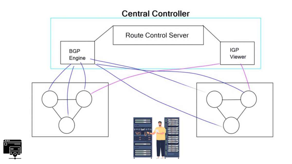
In a traditional BGP design, routers select paths using the routing information and policies available to them. Route Reflectors improve iBGP scalability, but their path-selection perspective can affect which routes are advertised to clients. An RCP-style architecture combines BGP information with an IGP topology view to compute routing decisions with a broader understanding of the network.

The engineering question: Can centralised routing intelligence improve path selection and scalability without placing the controller in the packet-forwarding path—and what happens when its network view is incomplete or stale?
01 · SEE

Understand the architecture

Explore how IGP topology, BGP reachability and routing policy feed a control platform that computes route decisions.

02 · OBSERVE

Compare routing perspectives

Examine why a Route Reflector and a controller using per-router topology information may choose different exits.

03 · INVESTIGATE

Diagnose incorrect decisions

Correlate topology freshness, IGP costs, BGP state and controller output to identify the cause of a suboptimal route.

Engineering outcome: understand the distinction between centralised route computation and distributed packet forwarding, evaluate RCP against Route Reflector designs, and identify the evidence needed to validate routing correctness.
NETWORK INSIGHT · ENGINEERING GUIDE
Routing Control Platform — Investigation Path

Follow the routing decision from architecture to operational verification. Each stage builds on the evidence collected in the previous one.

ENGINEERING ORIENTATION · 01 / SEE

How a routing decision travels through RCP

Select each stage to follow the control-plane workflow, from network information to packet forwarding.

Discover the networkThe platform needs a view of IGP topology, BGP routes and relevant policy before it can calculate a useful routing decision.

RCP Architecture: From Network State to Routing Decision

A Routing Control Platform (RCP) is an architectural approach to computing BGP routing decisions with a broader view of network topology, reachability and policy. Rather than relying exclusively on each router's local view, an RCP-style system collects routing information, evaluates it centrally and communicates routing decisions back to routers.

The important distinction is between where a routing decision is calculated and where packets are forwarded. RCP moves part of the route-computation process into a control platform. The routers still perform the actual packet forwarding using their local forwarding information base (FIB).

The engineering question

Can a controller use BGP information and IGP topology to make better-informed routing decisions without becoming a dependency in the normal packet-forwarding path?

1.1 The components of an RCP-style architecture

The original RCP concept separates information collection, route computation and route distribution. Exact component names and implementation details vary, but the following model captures the core responsibilities.

INPUT · TOPOLOGY
IGP topology view

Collects information about the internal network, including links, reachability and routing metrics. This helps the controller estimate the internal cost from a relevant router to a BGP next hop or external exit.

INPUT · REACHABILITY
BGP information

Provides reachable prefixes and path attributes such as AS_PATH, LOCAL_PREF, MED and next-hop information. The available paths depend on BGP propagation, policy and the architecture used to expose routes to the platform.

COMPUTE · CONTROL
Route Control Server (RCS)

Combines the available routing information with topology and policy to calculate routing decisions. Depending on the design, it may evaluate decisions from the perspective of particular routers or regions.

OUTPUT · ROUTING
Router RIB and FIB

Routers receive and process routing information, install eligible routes and program their local forwarding tables. Their forwarding hardware or software then sends packets toward the selected next hop.

1.2 Follow the route-decision flow

A useful way to understand the design is to trace one destination prefix from discovery to forwarding. The platform needs enough accurate information to make a decision, and the routers need a valid route and resolvable next hop to forward traffic successfully.

CONTROL-PLANE WORKFLOW
01 · Discover Learn IGP topology and BGP reachability.
02 · Correlate Combine paths, metrics and routing policy.
03 · Calculate Evaluate the appropriate route decision.
04 · Distribute Routers process routes and program forwarding state.
Simplified conceptual flow: actual RCP implementations differ in how they learn routes, compute decisions and distribute results.

1.3 Control plane versus data plane

RCP is not the same as a controller that forwards every packet centrally. It is primarily concerned with the computation and distribution of routing information. Once a router has installed a route and resolved its next hop, packets are normally forwarded locally.

Function Control plane Data plane
Primary purpose Learn reachability and determine usable routes. Forward packets using installed forwarding entries.
RCP's role Correlate BGP information, topology and policy to calculate routing decisions. Not normally in the packet-by-packet forwarding path.
Router's role Maintain routing protocols and process received routing information. Resolve the destination against the FIB and forward toward the next hop.
Evidence to inspect BGP routes, attributes, IGP topology, policy and controller state. Installed route, FIB entry, next-hop resolution and observed traffic.

1.4 Why the topology view matters

BGP path selection and internal path costs answer different questions. BGP attributes and policy influence which routes are eligible and preferred; IGP information helps establish internal reachability and costs to next hops. An RCP design attempts to use both kinds of information when calculating a decision.

Consider two external exits advertising the same destination. A central platform might know that Exit A is closer to one region while Exit B is closer to another. That information can support more appropriate router-specific decisions, provided the architecture can calculate and distribute those decisions correctly.

This does not mean that the lowest IGP cost always wins. LOCAL_PREF, AS_PATH, MED, next-hop reachability, policy and the implementation's decision process can affect the outcome. Engineers must inspect the full decision chain rather than infer the chosen route from one metric.

1.5 The design's dependency: accurate, current state

Centralised computation creates a strong dependency on the quality and freshness of the information being used. If a link fails but the controller still sees an older topology, it may calculate a route using a path that is no longer available. The resulting problem may appear as a route-selection issue even when the underlying cause is stale state or failed next-hop reachability.

  • Topology: Does the controller's view match the current IGP state?
  • Reachability: Are the BGP route and its next hop still valid?
  • Policy: Are route attributes and policy applied as intended?
  • Distribution: Did the target router receive and accept the intended route?
  • Forwarding: Does the local FIB reflect the route, and does traffic succeed?

1.6 RCP and Route Reflectors are not interchangeable terms

Route Reflectors address the scaling problem of a full iBGP mesh by reducing the number of required iBGP sessions. However, a reflector generally advertises selected paths according to its BGP decision process and configuration. Clients may therefore not receive every available path, and the reflector's routing perspective may differ from a client's perspective.

RCP was proposed as an alternative architectural approach to route computation and distribution, aiming to combine BGP information with topology knowledge. It should not be treated as a universal replacement for Route Reflectors or as a guarantee of optimal routing. Results depend on the implementation, information available, policies and network design.

Section 1 engineering takeaway

RCP separates routing-decision computation from packet forwarding. To understand a route, trace the complete chain: topology and BGP inputs → policy-aware calculation → route distribution → router RIB/FIB → verified traffic outcome. The next section compares the routing perspectives behind RCP and Route Reflectors.

How Does a Routing Control Platform Make a Routing Decision?

An RCP does not sit in the packet-forwarding path. It builds a broader view of routing and topology, computes policy-aware decisions, and communicates those decisions back to the routers.

Control Plane
Network State
IG
IGP / Topology
Link-state information gives the controller visibility of network connectivity and costs.
→
Routing Inputs
BG
BGP Information
The platform learns reachable prefixes, attributes and policy-relevant routing information.
→
Control Platform
R
Route Control Server
Combines topology, BGP state and policy to calculate the appropriate route for each perspective.
→
Decision Output
IB
Routing Update
The resulting route decision is distributed to the relevant BGP speakers.
→
Forwarding
F
Router FIB
Routers continue to forward packets locally using the route installed in their forwarding plane.
Topology Visibility
The controller needs a complete network view.

The key RCP idea is visibility. Instead of making a routing decision from the limited perspective of one router, the platform combines IGP topology information with BGP reachability and policy information.

Data Plane Routers forward traffic locally
Control Plane RCP computes routing decisions
Design Goal Global visibility + scalable distribution
rcp> Collecting IGP topology + BGP reachability → building routing view...
ENGINEERING ORIENTATION · 02 / OBSERVE

Who has the right view of the network?

Choose a routing model to examine how its decision-making perspective can affect exit selection.

Available evidenceThe reflector learns BGP paths it receives and evaluates them using its own routing information and policy context.
Engineering questionDoes the selected path suit the forwarding router, or only the reflector's perspective?
What to verify: Compare the selected BGP path with the client router's IGP cost, next-hop reachability and local policy. A reflector's best path is not automatically the best path for every client.
Section 2 · Observe routing perspectives

Compare Route Reflector and RCP Perspectives

Two routers can reach the same destination but have different internal costs to the available exits. Understanding which routing information is visible—and whose perspective drives the decision—is essential when investigating unexpected BGP paths.

Route Reflectors improve iBGP scalability by reducing the need for a full mesh of internal BGP sessions. A Routing Control Platform takes a different architectural approach: it seeks to combine BGP reachability and policy with a wider view of the IGP topology when calculating routing decisions.

Observation is not the same as optimisation

A controller or reflector can only make a decision from the information and policies available to it. To establish whether a route is appropriate, compare the selected BGP path, the relevant router's IGP costs, next-hop reachability and the actual forwarding state.

2.1 What does a Route Reflector see?

In a conventional route-reflector design, clients advertise routes to the reflector, which applies BGP selection and reflection rules. The reflector generally advertises selected paths rather than every path it learns. This reduces control-plane overhead, but it can limit which alternatives are visible to clients.

SCALABILITY
Fewer iBGP sessions

Route reflection reduces the need for every internal BGP router to peer directly with every other router. This simplifies session management as the network grows.

PATH VISIBILITY
Selected paths are reflected

Standard route reflection can hide alternatives that were not selected by the reflector. Additional mechanisms or design choices may be needed when greater path diversity is required.

ROUTING PERSPECTIVE
The reflector has its own view

The reflector's BGP decision is made in its own routing context. Its IGP cost to an exit can differ from the cost seen by a client in another part of the network.

VALIDATION
Check the receiving router

The reflected route must still be evaluated in the receiving router's context, including its installed next hop, local forwarding state and reachability.

2.2 What does an RCP-style design add?

RCP was proposed to address limitations associated with distributed route computation and route reflection. By combining BGP information with an IGP topology view, a controller can attempt to calculate decisions that account for the internal cost from a particular router or region to an exit.

The goal is not simply to select one globally best exit. In some designs, the appropriate choice differs by router because internal topology and policy differ. A platform that models these differences may be able to make better-informed decisions than one relying solely on a single reflector's perspective.

Example · Two exits, two router perspectives
Exit A IGP cost from West: 20
IGP cost from East: 70
Exit B IGP cost from West: 40
IGP cost from East: 15

Illustrative IGP costs only. If the relevant BGP paths and policy permit these choices, West may favour Exit A while East may favour Exit B. Actual BGP selection is not determined by IGP cost alone.

2.3 Compare the models using evidence

Engineering question Route Reflector RCP-style approach
What is the routing input? Received BGP routes, path attributes, local topology and configured policy. BGP reachability and policy combined with a collected view of IGP topology.
How are decisions made? The reflector applies its BGP decision process to the paths it knows. The platform calculates decisions using its available routing information and design-specific logic.
Can path diversity be limited? Yes. Conventional reflection may advertise only selected paths. Potentially different path visibility, depending on how the platform learns and distributes routes.
Can topology freshness matter? Yes. Local IGP state and next-hop reachability affect routing outcomes. Yes. Stale or incomplete topology information can undermine a calculated decision.
What proves the outcome? Received route, BGP attributes, local route selection and FIB. Input freshness, computed decision, distributed route, router RIB/FIB and traffic results.

2.4 Why the shortest internal path may not win

A common troubleshooting mistake is to assume that the router must use the exit with the lowest IGP cost. BGP selection is policy-driven and considers several attributes and decision steps. LOCAL_PREF, AS_PATH, MED, next-hop validity and implementation-specific configuration can influence which route is selected before or alongside internal forwarding considerations.

For example, a higher LOCAL_PREF can cause one path to be preferred even when its exit is farther away in the IGP. That can be intentional: an organisation may prefer a particular transit provider for commercial, security or traffic-engineering reasons. The engineer must first determine the intended policy, then compare the observed decision against it.

2.5 Build a reliable observation checklist

  • Route availability: Does the relevant router know the destination prefix?
  • Path attributes: Which candidate routes are visible, and what are their LOCAL_PREF, AS_PATH and MED values?
  • Router perspective: What are the IGP costs and next-hop reachability from the affected router?
  • Reflection or distribution: Was the intended route actually advertised to the client?
  • Controller freshness: If RCP is involved, does its topology snapshot reflect the current network?
  • Forwarding state: Does the local FIB match the expected route, and can traffic reach the destination?
Section 2 engineering takeaway

Do not judge a routing architecture by the route it selects in isolation. Compare the paths it can see, the topology and policy it uses, the router for which the decision is intended, and the resulting forwarding state. In the interactive lab that follows, compare exit selection from different router perspectives before investigating a deliberately incorrect decision in Section 3.

RCP Incident: Why Did One Region Get the Wrong Exit?

A routing incident has been reported. Reachability is healthy, BGP sessions are established, but one region is taking a suboptimal exit. Examine the evidence and identify the real control-plane problem.

Troubleshooting
Incident Report

Traffic from the West region is exiting through Exit B even though Exit A is significantly closer from the West router's IGP perspective. No BGP session is down.

BGP Session Established
Prefix Reachability Available
West → Exit A 18 IGP cost
West → Exit B 61 IGP cost
RR Selected Path Exit B
Controller Topology Stale by 9 min

What is the most likely root cause?

Network State West is closer to Exit A
→
Control Decision RR perspective selects Exit B
→
Topology Visibility Controller information is stale
→
Corrective Action Refresh topology and compute per-router paths
Engineering Insight

RCP does not simply mean “put BGP in a central box.” The value is the ability to combine network-wide state with the perspective of the router that actually needs the decision. That requires accurate topology visibility. If the controller is stale, the centralised decision process can be consistently wrong even though BGP sessions and basic reachability remain healthy.

ENGINEERING ORIENTATION · 03 / INVESTIGATE

A route looks valid—but the chosen exit is wrong

Explore the evidence an engineer should check before changing routing policy.

Check session health firstAn established BGP session confirms that the peer relationship is up; it does not prove the selected exit is optimal for this router.
Section 3 · Investigate the incident

Why Did One Region Get the Wrong Exit?

A BGP session can be established, a destination prefix can be present, and traffic can still take an unexpected path. When a Routing Control Platform uses topology information to calculate route decisions, an engineer must investigate both the routing inputs and the state from which those decisions were derived.

The critical skill is separating a symptom from its cause. An unexpected exit does not automatically mean that BGP is broken, that the destination is unreachable, or that LOCAL_PREF needs to be changed. The route may have been calculated using an outdated view of the internal network.

Incident hypothesis

One region prefers Exit B even though Exit A is closer according to the current IGP topology. BGP remains established and the destination is available. The controller's topology snapshot is several minutes old. Treat stale state as a hypothesis to verify—not as a conclusion to assume.

3.1 Start with the observed symptom

Imagine a network with two external exits advertising the same destination. The West region currently forwards through Exit B. An engineer's current IGP measurements show a lower cost to Exit A, but the controller still reports Exit B as the selected path.

OBSERVED
Unexpected exit selection

Traffic from West uses Exit B even though current topology measurements suggest Exit A is closer. Confirm the actual forwarding path instead of relying only on a dashboard summary.

KNOWN EVIDENCE
BGP is still established

The relevant BGP neighbour is up and the destination prefix is available. This makes a completely failed BGP session less likely, but does not rule out route-policy or path-distribution problems.

TOPOLOGY
Current costs differ

West's measured IGP costs are 18 to Exit A and 61 to Exit B. These figures are evidence about internal reachability—not proof that BGP must choose Exit A.

SUSPICIOUS STATE
Controller data is stale

The controller's topology snapshot is reported to be nine minutes old. Verify that timestamp and compare it with the actual IGP state and recent topology changes.

3.2 Follow the evidence in a deliberate order

Use a consistent investigation sequence to avoid changing policy before the cause is known. Each check should either support or eliminate a plausible failure mode.

01 · Confirm Reproduce the wrong exit and identify the affected router, prefix and traffic direction.
02 · Inspect Check BGP neighbour state, candidate paths, attributes and route availability.
03 · Compare Compare current IGP costs and next-hop reachability with the controller's recorded view.
04 · Validate Reconcile the topology, recompute the decision and verify the router's installed route and traffic.

3.3 Distinguish the possible causes

Possible cause Evidence to collect What it tells you
BGP session failure Neighbour state, logs, route withdrawal and session history. A down session can affect route availability, but an established session does not prove that the selected path is correct.
Missing route or next hop Received prefix, next-hop resolution, RIB and FIB entries. The route may be unavailable or unusable even when other BGP sessions remain up.
Policy or BGP attributes LOCAL_PREF, AS_PATH, MED, import/export policy and candidate-path visibility. A policy decision may legitimately override an engineer's expectation based on IGP distance alone.
Stale controller topology Snapshot timestamp, topology events, current IGP database and controller refresh status. The controller may be calculating from an older network state than the routers are using.
Distribution or installation problem Computed decision, advertised route, received route and local FIB. The intended decision may not have reached the router or may not have been installed as expected.

3.4 Why stale topology can produce a wrong decision

A topology-aware controller can only calculate from the information it has. If a link changes, a metric is updated or a failure occurs, the controller needs to learn the change and update its model. Until that happens, the controller's estimate of the path to an exit may no longer match the actual network.

This is a consistency problem between the observed network and the model used for route computation. The controller might produce a decision that was reasonable under the old topology but is no longer appropriate under the current one.

The effect depends on the implementation and the failure. A stale snapshot does not always cause an incorrect exit, a forwarding loop or a blackhole. It becomes operationally significant when the outdated information changes the computed decision or leaves a next hop unreachable.

3.5 Remediate the cause, not just the symptom

If evidence confirms that the topology view is stale, the corrective action is to restore accurate information and recalculate the route decision using the platform's supported recovery procedure. Avoid applying a blanket LOCAL_PREF change simply to force the desired exit: that may mask the issue and create unintended results for other regions or destinations.

  • Refresh: Restore topology collection or synchronisation and confirm that the controller has received the current state.
  • Recompute: Recalculate the route decision with current topology, BGP routes and policy.
  • Redistribute: Confirm that the intended routing update reaches the correct router or client.
  • Verify installation: Inspect the selected route, next hop and local FIB.
  • Verify service: Test the actual traffic path and confirm reachability and performance meet expectations.

3.6 What counts as proof that the incident is resolved?

A green controller status or a successful recalculation is not sufficient on its own. The investigation is complete when the inputs are current, the selected route matches the intended policy and topology, the router installs the expected forwarding entry, and traffic follows the intended path.

Section 3 engineering takeaway

Investigate unexpected routing by correlating BGP state, route attributes, current IGP costs, controller topology freshness, route distribution and FIB state. When the controller's view is stale, repair and verify the data pipeline before changing routing policy. The incident lab that follows lets you test this reasoning against the West-region scenario.

ENGINEERING ORIENTATION · 04 / CORRELATE & OPERATE

Recovery is not proven by a single green status

Select the evidence you have verified. A routing change is complete only when the control-plane decision and forwarding outcome agree.

Evidence verified: 0 of 4
Engineering takeaway: correlate topology, route selection, forwarding state and observed traffic. A correct BGP decision alone does not guarantee end-to-end service recovery.

Correlate and Operate: Validate the Routing Decision

A routing decision is not proven correct simply because a controller calculated a path or a router received an update. Engineers need to connect the network's topology, BGP information, policy decision, installed forwarding state and observed traffic into one evidence chain.

That is the operational challenge behind a Routing Control Platform (RCP). Its value depends not only on the decision logic, but also on the freshness and consistency of the information used to make decisions—and on whether the resulting routes are distributed and installed as intended.

Follow the evidence across the control and data planes

When a region takes an unexpected exit, investigate the complete sequence. A controller may have selected a valid route using an outdated topology snapshot; a router may have received the intended route but rejected it through policy; or the routing table may be correct while forwarding still fails because of a next-hop or downstream connectivity problem.

01
Topology and reachability Check IGP state, link costs, BGP sessions and reachable prefixes.
02
Decision and policy Confirm route attributes, policy inputs, router perspective and calculation time.
03
Distribution and installation Check the advertised route, receiving router's RIB and installed FIB entry.
04
Traffic and stability Test the real path, service outcome, convergence and post-change behaviour.

Correlate symptoms with the right evidence

Observed symptom Evidence to correlate Engineering interpretation
Unexpected exit selected IGP costs, BGP attributes, policy, topology timestamp and router perspective The choice may reflect policy or a different network view—not necessarily a failed session.
Route missing from a router Received updates, import policy, next-hop reachability and routing table The route may be unavailable, filtered, ineligible or not installed.
Route present, traffic fails FIB entry, resolved next hop, interface state, ACLs and end-to-end probes Control-plane reachability does not by itself prove successful packet delivery.
Repeated path changes Update history, attribute changes, topology events, timers and policy interactions Look for interacting decisions or unstable inputs before changing attributes.

Understand the mechanisms around route selection

Hot-potato routing

Hot-potato routing generally favours the closest eligible exit according to the router's IGP view after higher-priority BGP decision criteria have been considered. Two routers can legitimately choose different exits because their IGP costs differ. A controller's view must therefore match the intended decision perspective; a low IGP cost alone does not override every BGP attribute or policy.

Multipath and BGP Add-Path

BGP multipath can allow multiple eligible paths to be installed or used, subject to implementation and configuration. BGP Add-Path allows multiple paths for a prefix to be advertised to a peer, helping reduce some path-visibility limitations. Neither feature automatically guarantees a better path or removes the need to validate policy, next-hop resolution and forwarding behaviour.

Next-hop tracking and MED

Next-hop tracking helps a router reassess route eligibility when next-hop reachability changes. MED can influence selection between routes from the same neighbouring AS, depending on the comparison rules and policy. In complex designs, interacting MED values, route reflection and changing topology can contribute to repeated path changes—but oscillation is not inevitable. Examine the actual attributes, decision order and update sequence before attributing a problem to MED.

Design boundary: RCP is a historically important control-plane architecture, not a universal modern product or a guaranteed replacement for Route Reflectors. Any centralised or controller-assisted design must account for failure modes, topology freshness, policy consistency, route distribution, controller redundancy and safe fallback behaviour.

A safe recovery workflow

Once the evidence points to stale or inconsistent topology, avoid making unrelated policy changes just to force a preferred exit. Correct the underlying input first, then confirm each downstream stage.

DetectReconcileRecomputeRedistributeVerify

  1. Capture the baseline. Record the affected prefix, selected exit, IGP costs, BGP attributes, relevant updates and current RIB/FIB state.
  2. Reconcile the network view. Confirm that topology data and reachability reflect current link and routing state. Check timestamps and the source of the data.
  3. Recompute and distribute. Re-evaluate the route using the intended policy and perspective, then verify that the expected decision reaches the affected routers.
  4. Verify installation. Confirm the route in the router's RIB, resolve the next hop and check the corresponding FIB entry. A received update is not the same as an installed route.
  5. Test the service and monitor. Use appropriate path probes or traffic tests, watch for unexpected updates or route churn, and retain a rollback path if the change causes regressions.

How do you know the incident is resolved?

Recovery is complete only when the intended route decision is visible, the forwarding entry is installed, the next hop is reachable, traffic behaves as expected and the system remains stable after convergence. Record the before-and-after evidence so that the fix can be explained and repeated—not merely assumed from a green status indicator.

Engineering takeaway Treat routing as an evidence chain: topology and reachability → BGP attributes and policy → route decision → route distribution → RIB/FIB installation → observed traffic. Verify every stage before declaring recovery.

Engineering conclusion · Routing control

From Centralised Routing Intelligence to Verified Forwarding

The Routing Control Platform concept highlights a fundamental challenge in BGP engineering: a route-selection decision is only as reliable as the network information, policy and router perspective behind it.

By combining BGP reachability with IGP topology information, an RCP can calculate routing decisions with a broader view of the network. The operational challenge is ensuring that this view remains accurate, the intended decisions reach the relevant routers, and the resulting forwarding state delivers the expected outcome.

Four engineering principles to take away

01 · Understand the architecture Separate topology discovery, BGP route information, route computation and packet forwarding.
02 · Compare perspectives Account for route visibility, IGP costs, BGP attributes and policy before explaining an exit choice.
03 · Investigate with evidence Distinguish session failure, missing reachability, policy effects, stale topology and installation problems.
04 · Verify the outcome Confirm the selected route, installed forwarding entry, next-hop reachability, traffic behaviour and stability.

The broader lesson for software-defined networking

RCP is a useful architectural case study in separating routing intelligence from packet forwarding. Its ideas remain relevant when evaluating controller-assisted networking, centralised policy, topology-aware path computation and modern network automation. However, an architecture should be judged against its actual implementation, failure handling, scalability and operational requirements—not treated as a universal replacement for established BGP designs.

The engineer's final test is not whether the controller calculated a route. It is whether the intended route was installed, traffic followed the expected path, and the network remained stable.

RCP vs Route Reflector: Which Exit Does Each Router Choose?

Experiment with the network perspective, IGP costs and routing policy. Then run the decision engine to see how a traditional Route Reflector and an RCP can produce different exit choices.

Interactive Lab
Ready: Change the conditions and run the decision engine.
Route Reflector Shared decision
Selected Exit Exit A
The RR makes the best-path decision from its own reference point and reflects that selected route to clients.
RR → Exit A 20
RR → Exit B 40
Result delivered to client Exit A
Routing Control Platform Per-router decision
Selected Exit Exit A
The RCP evaluates the available exits using the selected router's network perspective.
Router → Exit A 20
Router → Exit B 65
Decision comparison Same as RR
Routing Perspective Awaiting calculation
SOURCE WEST
RR1 RR view
ROUTER WEST VIEW
EXIT A EGRESS
EXIT B EGRESS
A: 20
B: 40
RR-selected path
Exit A
Exit B
Engineering Insight

The important difference is network perspective. A Route Reflector provides scalability by reflecting selected routes, while an RCP can calculate the appropriate route for the individual router using broader topology visibility.

☕
Support Network Insight
Help support the development of interactive networking labs, BGP simulations, and educational content.
Support the Project