Port Channels and vPCs
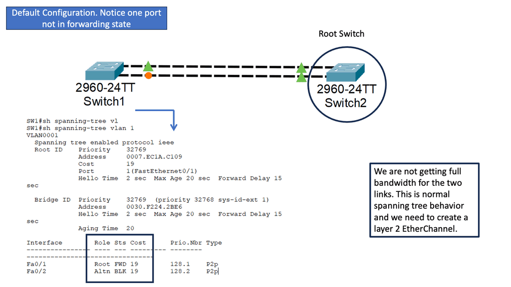
During the early days of Layer 2 Ethernet networks, Spanning Tree Protocol (STP) was used to limit the devastating effects of a topology loop. Even though there may be many connections in a network, STP has one suboptimal principle: only one active path is allowed between two devices.
There are two problems with a single logical link: the first is that half (or more) of the system’s bandwidth is unavailable to data traffic, and the second is that if the active link fails, the network will experience multiple seconds of systemwide data loss as it re-evaluates the new “best” solution to network forwarding on a Layer 2 network.
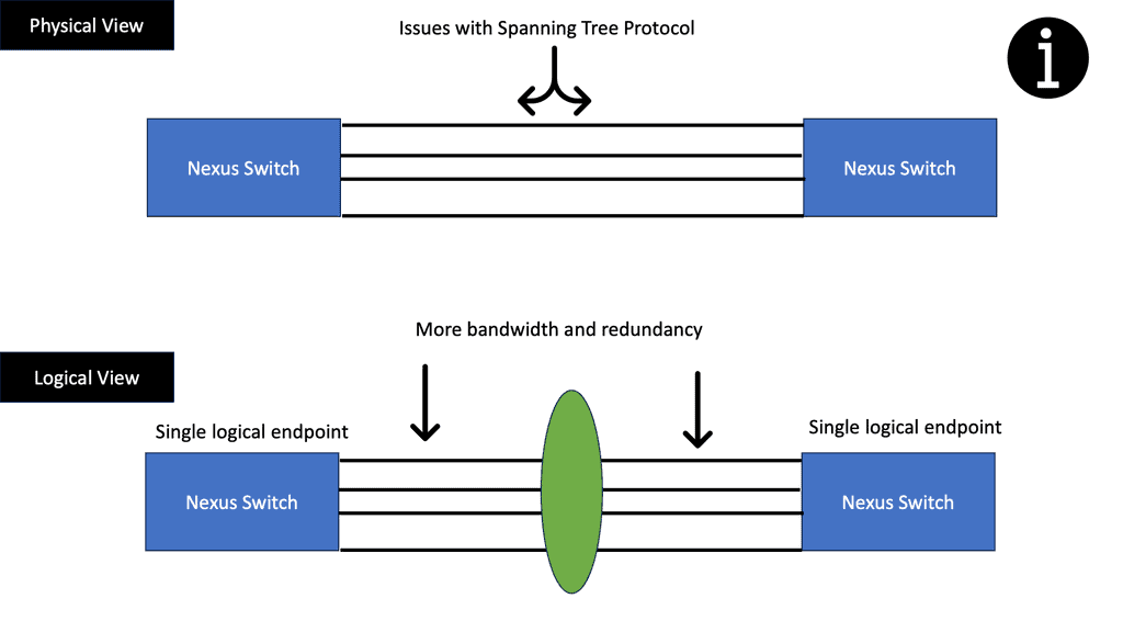
One of the significant drawbacks of the spanning tree is the concept of blocking ports. While they are essential to prevent loops, blocking ports leads to inefficient network performance. The blocked ports essentially go unused, resulting in unused bandwidth and decreased overall network throughput.
Load Balancing
Furthermore, in a robust network with STP loop management, there is no efficient dynamic way to utilize all the available bandwidth. Enhanced Layer 2 Ethernet networks have been developed through the use of port channels and virtual port channels (vPCs). Port Channel technology allows forwarding traffic between two participating devices using a load-balancing algorithm to balance traffic across multiple inter-switch links (ISLs).
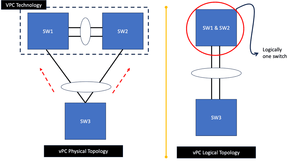
By bundling the links together as one logical link, the loop problem is also managed. Multi-device port channels can be formed using vPC technology. Port channel-attached devices see a pair of switches acting as a single logical endpoint when attached to a vPC peer; the devices act as separate endpoints. By combining hardware redundancy with port-channel loop management, the vPC environment provides multiple benefits.
Example: Cisco ACI
These technologies are extensively used in the ACI Cisco. A virtual port channel (vPC) allows links physically connected to two different ACI leaf nodes to appear as a single port channel to a third device (i.e., network switch, server, or any other networking device that supports link aggregation technology). Firstly, let us start with the basics.
**Spanning Tree Challenges**
Traditional spanning trees challenge network designers as they block redundant links. The drawbacks of STP ( spanning tree protocol ) prove extremely expensive in data centers when multiple redundant links are used for mission-critical applications, essentially wasting 50% of the capacity.
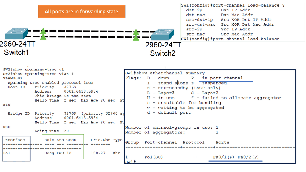
You can use the port channel to scale bandwidth, as the bundled links appear as one to higher-level protocols, resulting in all ports forwarding or blocking for a particular VLAN. It would help if you aimed to design all links in a data center as an EtherChannel, as this will optimize your bandwidth and reliability.
EtherChannel Technology
Network administrators connect multiple physical Ethernet links between devices to achieve more bandwidth and redundancy. The Spanning Tree Protocol blocks these links, so we need EtherChannel Technology. EtherChannel technology combines several physical links between switches into one logical connection to provide high-speed links and redundancy without being blocked by the Spanning Tree Protocol.
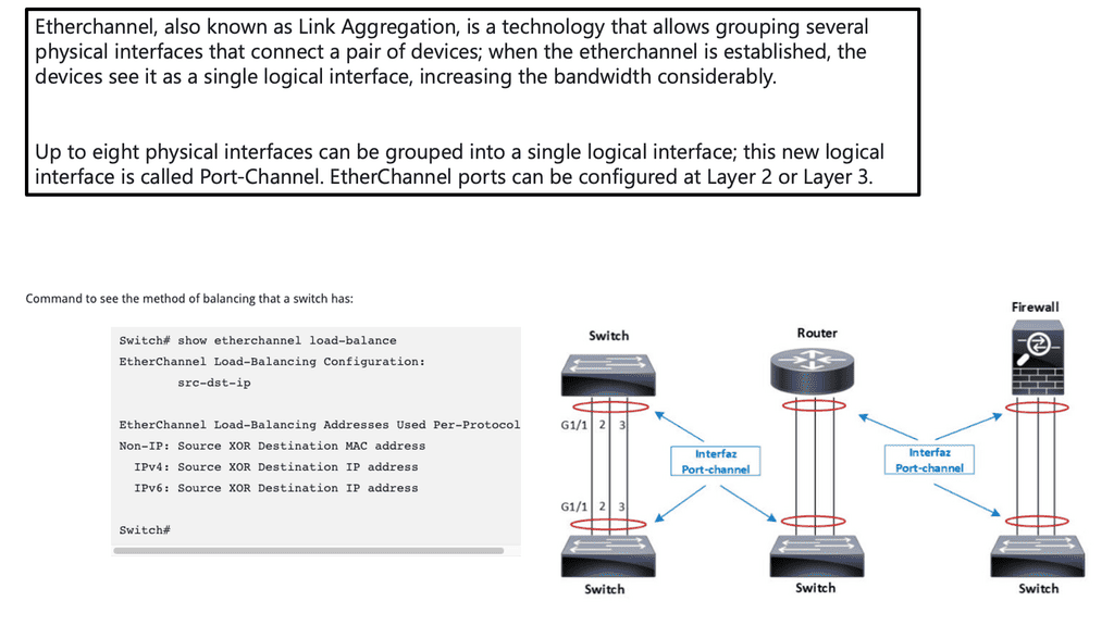
Understanding Layer 2 EtherChannel
Layer 2 EtherChannel, also known as Link Aggregation or Port Channel, combines multiple physical links into a single logical link. This powerful technique enhances bandwidth, improves redundancy, and optimizes load balancing. By bundling multiple links, Layer 2 EtherChannel presents a unified interface for higher throughput and fault tolerance.
Configuring Layer 2 EtherChannel involves steps that vary depending on the networking equipment used. Generally, it starts with identifying the physical links that will be part of the EtherChannel bundle. Then, the appropriate channel mode and load balancing method must be configured. Lastly, the EtherChannel interface is created, and the physical links are assigned. Proper configuration ensures seamless data transmission and efficient utilization of network resources.
Understanding Layer 3 Etherchannel
Layer 3 Etherchannel, also known as routed Etherchannel or port-channel, bundles multiple physical interfaces into a single logical interface to increase bandwidth and provide redundancy at Layer 3. Unlike Layer 2 Etherchannel, which operates at the data link layer, Layer 3 Etherchannel operates at the network layer, allowing traffic distribution across multiple physical links based on routing protocols.
Layer 3 Etherchannel offers several advantages over traditional single link configurations. Firstly, it allows for load balancing, where traffic is distributed across multiple links, maximizing bandwidth utilization and improving overall network performance. Additionally, Layer 3 Etherchannel provides redundancy, ensuring that traffic seamlessly switches to the remaining active links if one link fails, minimizing downtime, and enhancing network reliability.
Configuration of Layer 3 Etherchannel
Configuring Layer 3 Etherchannel involves a few essential steps. Firstly, the physical interfaces that will be part of the Etherchannel bundle must be identified and prepared. Then, a logical interface, often called a port-channel interface, is created. This interface acts as the virtual representation of the bundled physical links. Next, the routing protocol must be configured to distribute traffic across the links. Finally, verification and testing are crucial to ensure proper configuration and functionality.
Layer 3 Etherchannel finds its applications in various scenarios. One everyday use case is in data centers, where high-speed connectivity and redundancy are critical. By bundling multiple links, Layer 3 Etherchannel provides the bandwidth and failover capabilities required for demanding data center environments. Another use case is in network edge deployments, where Layer 3 Etherchannel allows for efficient load balancing and redundancy in connecting access switches to distribution or core switches.

Port Channel and vPC
Port Channel technology forwards traffic between two participating devices using a load-balancing algorithm. Multiple devices can form a virtual port channel (vPC). A third device can see two Cisco Nexus 7000 or 9000 Series devices as a single port channel using a virtual port channel (vPC). Third devices can be switches, servers, or other networking devices that support port channels.
A virtual private cloud can provide Layer 2 multipathing to create redundancy and increase bandwidth by enabling multiple parallel paths between nodes and load-balancing traffic. The only ones you can use in the vPC are Layer 2 port channels. LACP or a static no protocol configuration is used to configure the port channels.
vPC provides the following technical benefits:
- A single device can share a port channel between two upstream devices
- Spanning Tree Protocol (STP) blocked ports are removed
- Makes sure there are no loops in the topology
- Uplink bandwidth is utilized to the fullest extent possible
- When either a device or a link fails, the system quickly converges
- Resilience at the link level is ensured
- Ensures a high level of availability
**Implementation of vPC topologies**
VPC supports the following topologies:
- Dual-uplink Layer 2 access: Using a Cisco Nexus 9000 Series switch, an access switch is dual-homed to a pair of distribution switches.
- Dual-homing: This topology connects two servers to two switches,
- Topologies supported by FEX: FEX supports various vPC topologies using Cisco Nexus 7000 and 9000 Series switches.

Related: For pre-information, you may find the following posts helpful:
STP has one suboptimal principle: to break loops in a network. This issue with having a single practice is that only one active path is allowed from one device to another, regardless of how many connections might exist in the network. In addition, no efficient dynamic mechanism exists for using all the available bandwidth with STP loop management.
- Port Channel Technology
So, to overcome these challenges, enhancements to Layer 2 Ethernet networks were made in the shape of port channel and virtual port channel (vPC) technologies. Port Channel technology permits multiple links between two participating devices to forward traffic using a load-balancing algorithm while managing the loop problem by bundling the links as one logical link.
- vPC Technology
Then, we have vPC technology. This technology permits multiple devices to create a port channel. In vPC, a pair of switches acting as a vPC peer endpoint looks like a single logical entity to port channel–attached devices; the two devices that serve as the logical port-channel endpoint are still two different and separate devices.
High Availability: Link and Device.
You need to identify the level of high availability you want to achieve in enterprise branch offices. Then, you can meet your high availability requirements with the appropriate device level and link redundancy.
Link-level redundancy requires two links to run as active/active or active/backup links to recover traffic forwarding lost if one link fails. Therefore, any failure on an access link should not result in a loss of connectivity. To qualify, a branch office must have at least two upstream links, either to a private network or the Internet.
Device-level redundancy is another level of high availability, ensuring that the backup device can take over in the event of a failed device. Device and link redundancy is typically coupled, which means that if one fails, the other will too. As a result of this strategy, there should be no loss of connectivity between branch offices and data centers due to a single device failure.
High Availability and Designs
High-availability designs combine link and device redundancy between branches and data centers to ensure business-critical connectivity. Each data center is dual-homed, so if one fails, traffic can be redirected to the backup data center in the event of a complete failure.
Reroute traffic within 30 seconds should be possible whenever a failure (link, device, or data center) occurs. Packets can be lost during this period. When the user applications can withstand these failover times, sessions are maintained. Established sessions should not be dropped in a branch office with redundant devices if the failed device was forwarding traffic.
**vPC vs Port Channel**
Servers can be attached to the access switches as port channels, uplinks that consist of redundant links formed from the access can be link aggregated, and the core links can also be bundled. Most switches can support 8 ports in a bundle, and Nexus platforms can support up to 16 – 32 ports.
It would help to create a port channel with ports from different line cards in each redundant switch. This will prevent the failure of a single line card from affecting the entire channel. With this approach, we get redundancy at a logical and physical layer.
Link Aggregation and Port Channels
Link aggregation (EtherChannel and IEEE 802.3ad ) was developed to address that limitation where two Ethernet redundant switches were connected through multiple up-links. However, this did not address the challenges in the data center environment for deploying link aggregation on triangular topologies or if you want to terminate on different switches.
Traditional LAG ( link aggregation ) has limitations because its standard only allows aggregated links to terminate on a single switch. Technologies such as vPC Virtual Port Channel and Virtual Switching System (VSS) have been implemented to overcome this limitation.
Key Points: Port Channels
In summary, a port channel aggregates multiple physical interfaces that create a logical interface. On some platforms, you can bundle up to 32 individual redundant links. The Port channel will also load balance traffic across the redundant links. The port channel will remain operational as long as at least one physical interface within the port channel is operational. Finally, before we move to vPC vs port channel, you can create either Layer 2 or 3 port channels. However, as expected, you cannot combine Layer 2 and 3 interfaces in the same port channel.
Port-channel load balancing
Frames are distributed between the physical interfaces that make up the port channel using a hashing function. This hash will differ depending on the load balancing method. Based on the hash result, the physical port to be used for transmission is determined.
A hashing operation can be performed on MAC or IP addresses based on the source address, destination address, or both (some methods use the port number). Depending on the switch model and software version, default load-balancing methods can be layer 2, 3, or 4 and apply globally to all port channels. Here are a few methods for balancing etherchannels:
- src-ip : Source IP address
- dst-ip : Destination IP address
- src-dst-ip : Source and destination IP address
- src-mac : Source MAC address
- dst-mac : Destination MAC address
- src-dst-mac : Source and destination MAC address
- src-port : Source port number
- dst-port : Destination port number
- src-dst-port : Destination source port number
Starting the Debate: vPC vs Port Channel
vPC (Virtual Port-Channel), or multi-chassis ether channel (MEC), is a feature on the Cisco Nexus switches. You can configure port channels across multiple redundant switches. The virtual port channel (vPC) is configured using the interfaces of two redundant switches.
Now we have redundancy at a link and a switch layer forming a triangular design. We must terminate the links with a standard port channel on the same switch. We don’t have a channel between two redundant switches in this case.
Virtual PortChannels (vPCs), links between two Cisco switches, appear to a third downstream device as coming from one device and as part of a single PortChannel. A third device can be a switch, a server, or other networking devices that support IEEE 802.3ad PortChannels. Both standard port channels and Virtual PortChannels (vPC) can use the link Aggregation Control Protocol ( LACP ).
LACP negotiation and redundant switches
As part of the IEEE 802.3ad standards, a Link Aggregation Control Protocol ( LACP ) was created to negotiate the channel, and it is recommended that this feature be used when building a bundle. LACP modes can be either active or passive. Active mode means the switch actively negotiates the channel, whereas passive means the port does not initiate an LACP negotiation.
You can form channels between active and passive or two active ports but not passive and passive ports. The port channel will not negotiate and remain down if the correct modes are not configured on each side of the challenge.
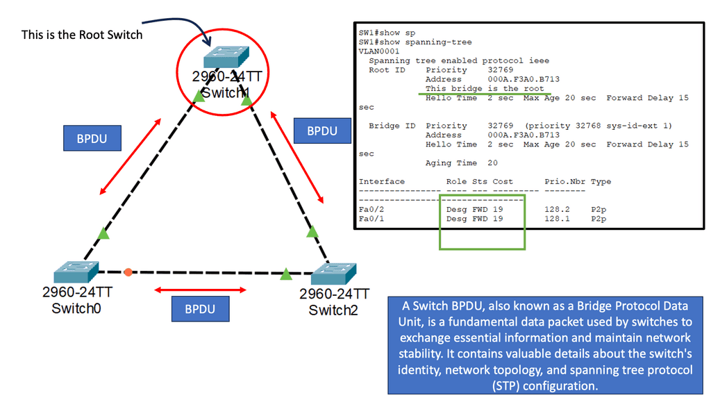
The following diagram depicts the logic and physical aspects of a vPC virtual port channel. This is not specific to a Cisco vPC but all aggregation technologies. We have several physical redundant links; in our case, four appear to be one prominent link from a logical perspective.
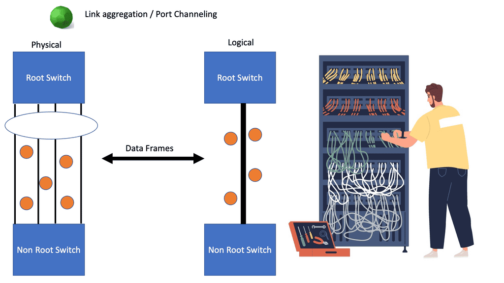
In either case, LACP can be used as the control plane to negotiate the channel. You may ask, is LACP mandatory for vPC?” – No. We can use mode “On” & bring UP the port channel without negotiation/checks. So, we are turning off the LACP or other control protocols. However, is LACP recommended for vPC?” –
Like a normal port channel, it is always advised to use a control protocol for the vPC/port channel. LACP adds a lot of intelligence to the background. The main difference between vPC and port channels is that vPC can terminate on secondary switches, creating a triangular design.
Building triangles for better redundancy
The quandary of the inability to build triangles with link aggregation can be mitigated by deploying either the Nexus technology, known as virtual Port Channels (vPCs), or the Catalyst technology, known as Virtual Switching System ( VSS ). VSS and vPC virtual port channels allow the termination of an LAG on two separate switches, resulting in a triangular design. In addition, they will enable the grouping of two physical redundant switches to form a single logical switch to any downstream device ( switch or server ).
Load Balancing Functions
A hash function is performed when a layer 2 frame is forwarding to a PortChannel to determine which physical links to forward the frame. The load balancing method used for Nexus switches is granular and includes the following:
Nexus Switches | Load Balancing Method |
Option 1 | Destination IP address |
Option 2 | Destination MAC address |
Option 3 | Destination TCP and UDP port number |
Option 4 | Source and Destination IP address |
Option 5 | Source and Destination MAC address |
Option 6 | Source and Destination TCP and UDP port numbers |
Option 7 | Source IP address |
Option 8 | Source MAC address |
Option 9 | Source TCP and UDP port number |
Redundant Links: Detect polarized links
Monitoring the traffic distribution over each physical link is essential to detect polarized links. The polarization effect occurs if some links attract more traffic than others, resulting in heavy utilization of some redundant links and low utilization of others. Therefore, before choosing the load balancing method, analyze the traffic flows from source to destination and determine if the flow is too many or evenly spread. For example, I would not use the source IP address load balancing method to load balance traffic from a firewall deploying Network Address Translation ( NAT ) to a single device.
Routing Protocols
Keep in mind for routing convergence, that routing protocols see the channel as one link, so if you have 8 x 10 ports in one bundle and that bundle has an OSPF cost of 10, a failure occurs, and you lose a member of that channel, the OSPF will still mark that link with the same metric. Routing protocols don’t dynamically change metrics due to a member link failure.
vPC and VSS offer the following benefits:
Redundant links with Virtual PortChannels | |
Improved convergence with a link and device failure. | |
Eliminate the need for STP. | |
Independent control planes ** Not with the VSS. | |
Increased bandwidth but combining all redundant links to one from the perspective of STP. |
What is vPC?
MEC (Multi-Chassis EtherChannel) is a feature on Cisco Nexus switches that allows you to configure a Port-Channel across multiple switches (i.e., vPC peers). Virtual PC is similar to Virtual Switch System (VSS) on Catalyst 6500s. However, VSS creates just one logical switch instead of vPC’s multiple ones. In this way, a single control plane handles both management and configuration.
vPC, on the other hand, allows each switch to be managed and configured independently. vPC manages both switches independently, so it’s important to remember that. Therefore, you must create and permit your VLANs on both Nexus switches.
Comparing vPC and VSS
vPC and VSS are similar technologies, but the Nexus vPC feature has dual control planes. It offers In-Service Upgrade ( ISSU ), which allows upgrading one of the two switches without causing any service interruption. Because the control plane runs independently on each of the vPC peers, the failure of one peer does not affect the virtual switch.
With the VSS, the active peer going down brings down the entire system because of the lack of dual control planes. It should be worth noting that vPC falls back to STP, and the reliance on STP can only be entirely circumvented if you use Cisco’s Fabric Path or THRILL. The VSS is available on the Catalyst platforms, while vPC is solely a Nexus technology.
**vPC Terminology:**
- vPC Peer – a vPC switch, one of a pair.
- vPC member port – one of the ports that form a vPC.
- vPC – the combined port channel between the vPC peers and the downstream device.
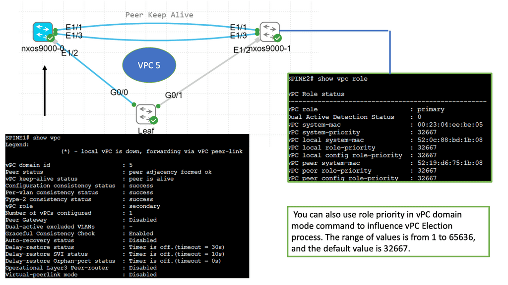
- vPC peer-link – link used to synchronize state between vPC peer devices, must be 10GbE. The vPC-related control plane communications occur over this link, and any Ethernet frames transported receive special treatment to avoid loops in the vPC member ports.
- vPC peer keepalive link – the keepalive link between the vPC peer devices. It recommended using the MGMT0 interface and a VRF instance. If the mgmt interface is unavailable, then a routed interface in the mgmt VRF is.
- vPC VLAN – one of the VLANs that carry over the vPC peer link and communicate via the vPC with a peer device.
- non-vPC peer VLAN – One STP VLAN is not carried over the peer link.
- CFS – Cisco Fabric Service Protocol, used for state synchronization and configuration validation between vPC peer devices.
Within a vPC domain, each pair is assigned to a primary or secondary role; by default, the switch with the lowest MAC address becomes the primary peer. The domain identifies the pair of redundant switches, generating a shared MAC address that can be used as a logical switch bridge ID in STP communication.
Virtual PortChannels Best Practices
Below are the best practices to consider for implementation:
- Manually define which vPC switch is primary and secondary. Lower the priority, and the more preferred switch will act as the primary.
- Form Layer 2 port channels using different 10GE modules on the Nexus switch for the vPC peer-link with ports in dedicated mode.
- Form Layer 2 port channels using different 10GE modules on the Nexus switch for the vPC peer keepalive link ( non-default VRF ).
- Enable Bridge Assurance ( BA ) on the vPC peer-link interface ( default ).
- Enable UDLD aggression on the vPC peer-link interface.
- On the primary vPC switch, configure the STP root bridge for a VLAN, the active HSRP router, and the PIM DR router. Likewise, on the secondary vPC switch, configure the secondary STP and the standby HSRP router. The Layer 2 and Layer 3 topologies should match.
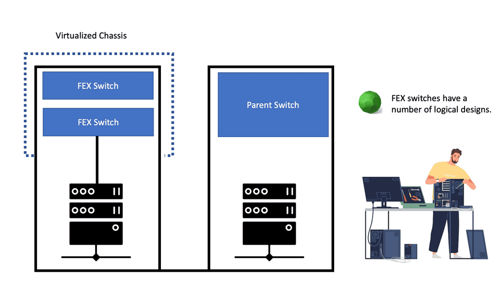
Introducing Fabric Extenders
If you want to add even more redundancy to vPC, use it with a fabric extender. Fabric Extenders act as a remote line card to a parent switch and can be used with vPC in three forms. The first is known as host vPC and is a vPC southbound from the FEX to the server; the second is a vPC northbound from the FEX to the parent switch, sometimes called a Fabric vPC; and the third is both a southbound and northbound vPC from the FEX which is known as Enhanced vPC.
Virtual PortChannels, the single connection
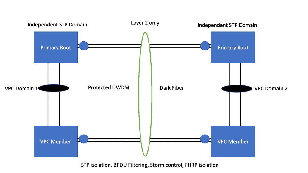
- Datacenter interconnect
Because vPC characterizes a single connection from the perspective of higher-level protocols, e.g., STP or OSPF, it can be used as a Layer 2 extension for a DCI ( data center interconnect ) over short distances and dark fiber or protected DWDM only. vPC best practices still apply, and it is recommended that you use different vPC domains for each site and that Layer 3 communication between vPC peers is performed on dedicated routed redundant links.
- OTV or VPLS
If you connect more than two data centers with an entire mesh topology, the best DCI mechanism would be Overlay Transport Virtualization (OTV) or VPLS ( Ethernet-based point-to-multipoint Layer 2 VPN ). vPC can work with two or more data centers, but you must design the topology as a hub-and-spoke.
Any spoke-to-spoke communication must flow through the hub, connecting two data centers back to back or two or more in a hub-and-spoke design. The layer 2 boundary and STP isolation can be achieved with bridge protocol unit ( BPDU ) filtering on the DCI links. BPDU filtering avoids transmitting BPDUs on a link, essentially turning off STP on the DCI links. You can extend with the multi-pod or multi-site designs if you have Cisco ACI.
- A key point: Loop prevention
vPC has a built-in loop prevention mechanism; never forward a frame received through a peer link to a vPC member port. Under normal operations, a vPC peer switch should never learn MAC addresses over the peer link and is mainly used for flooding, multicast, broadcast, and control plane traffic.
This is because the LAG is terminated on two peer switches, and you don’t want to send traffic received from a single downstream device back down to the same downstream device, resulting in a loop. However, this rule does not apply to:
- Non-vPC interface ( orphan port ) and
- vPC member ports that are only active in the receiving pair.
Note: An orphan port in a port to a downstream device connected to only one peer.
Redundant Switches: vPC peer link usage
As mentioned, the vPC peer link should not be used for end-host reachability under normal operations. However, if there is a failure on all members of a vPC in a single peer, the peer link will forward frames to the remaining member ports of the vPC. This explains why Cisco has recommended using the same 10G for the peer link.
The peer keepalive link is also mandatory and is used as a heartbeat mechanism to transport UDP datagrams between peers. This avoids a dual-active / split-brain scenario where both peers are active simultaneously. If no heartbeat is received after a configurable timeout, the secondary vPC peer is the primary peer, and all its member ports remain active.
However, undesirable behavior occurs if an orphan port is connected to only one peer. For example, with a vPC peer link failure, the orphan ports remain active in the secondary peer, even though they are now isolated from the rest of the network. In this case, it is recommended that a non-vPC trunk be configured between peer switches.
Closing Points on Redundant Links with Virtual Portchannels
vPCs allow multiple links to function as a single logical channel, offering improved bandwidth and fault tolerance. This technology not only enhances performance but also simplifies network design, making it a vital tool for modern enterprises.
Redundant links are the backbone of a resilient network architecture. They ensure uninterrupted data flow even when a primary link fails, thus maintaining the network’s integrity. However, traditional methods of setting up redundancy often lead to complexities such as network loops and inefficient bandwidth utilization. Virtual Portchannels address these issues by aggregating multiple physical links into one logical entity. This aggregation helps in balancing loads more effectively and reduces the potential for network congestion.
Adopting vPCs in your network infrastructure offers several benefits. First and foremost, they provide increased bandwidth by combining the throughput of multiple links. Additionally, vPCs enhance redundancy without the need for complex configurations, resulting in simpler network management. Another significant advantage is the elimination of Spanning Tree Protocol (STP) issues. By bypassing STP, vPCs decrease the risk of network loops and provide a more stable networking environment.
While vPCs present numerous advantages, they are not without challenges. Implementing vPCs requires careful planning and a thorough understanding of both hardware and software configurations. Network administrators must ensure compatibility between devices and be prepared to troubleshoot issues related to synchronization and consistency. Furthermore, as with any technology, ongoing maintenance and monitoring are essential to ensure optimal performance and reliability.