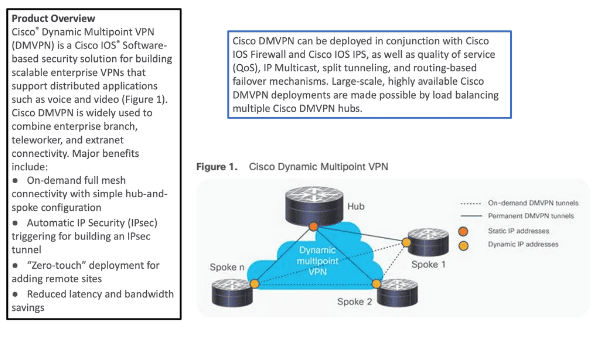
Highlighting DMVPN Phase 1 2 3
Dynamic Multipoint Virtual Private Network ( DMVPN ) is a dynamic virtual private network ( VPN ) form that allows a mesh of VPNs without needing to pre-configure all tunnel endpoints, i.e., spokes. Tunnels on spokes establish on-demand based on traffic patterns without repeated configuration on hubs or spokes. The design is based on DMVPN Phase 1 2 3.
- Point-to-multipoint Layer 3 overlay VPN
In its simplest form, DMVPN is a point-to-multipoint Layer 3 overlay VPN enabling logical hub and spoke topology supporting direct spoke-to-spoke communications depending on DMVPN design ( DMVPN Phases: Phase 1, Phase 2, and Phase 3 ) selection. The DMVPN Phase selection significantly affects routing protocol configuration and how it works over the logical topology. However, parallels between frame-relay routing and DMVPN routing protocols are evident from a routing point of view.
- Dynamic routing capabilities
DMVPN is one of the most scalable technologies when building large IPsec-based VPN networks with dynamic routing functionality. It seems simple, but you could encounter interesting design challenges when your deployment has more than a few spoke routers. This post will help you understand the DMVPN phases and their configurations.
DMVPN Phases. |
|
DMVPN allows the creation of full mesh GRE or IPsec tunnels with a simple template of configuration. From a provisioning point of view, DMPVN is simple.
Before you proceed, you may find the following useful:
- A key point: Video on the DMVPN Phases
The following video discusses the DMVPN phases. The demonstration is performed with Cisco modeling labs, and I go through a few different types of topologies. At the same time, I was comparing the configurations for DMVPN Phase 1 and DMVPN Phase 3. There is also some on-the-fly troubleshooting that you will find helpful and deepen your understanding of DMVPN.
Back to basics with DMVPN.
- Highlighting DMVPN
DMVPN is a Cisco solution providing scalable VPN architecture. In its simplest form, DMVPN is a point-to-multipoint Layer 3 overlay VPN enabling logical hub and spoke topology supporting direct spoke-to-spoke communications depending on DMVPN design ( DMVPN Phases: Phase 1, Phase 2, and Phase 3 ) selection. The DMVPN Phase selection significantly affects routing protocol configuration and how it works over the logical topology. However, parallels between frame-relay routing and DMVPN routing protocols are evident from a routing point of view.
- Introduction to DMVPN technologies
DMVPN uses industry-standardized technologies ( NHRP, GRE, and IPsec ) to build the overlay network. DMVPN uses Generic Routing Encapsulation (GRE) for tunneling, Next Hop Resolution Protocol (NHRP) for on-demand forwarding and mapping information, and IPsec to provide a secure overlay network to address the deficiencies of site-to-site VPN tunnels while providing full-mesh connectivity.
In particular, DMVPN uses Multipoint GRE (mGRE) encapsulation and supports dynamic routing protocols, eliminating many other support issues associated with other VPN technologies. The DMVPN network is classified as an overlay network because the GRE tunnels are built on top of existing transports, also known as an underlay network.
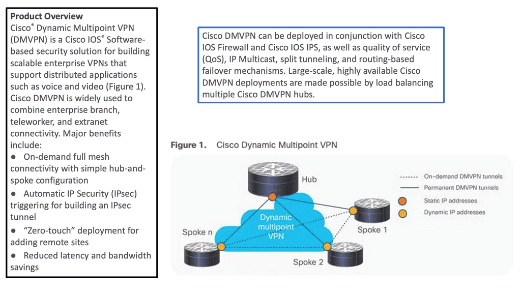
DMVPN Is a Combination of 4 Technologies:
mGRE: In concept, GRE tunnels behave like point-to-point serial links. mGRE behaves like LAN, so many neighbors are reachable over the same interface. The “M” in mGRE stands for multipoint.
Dynamic Next Hop Resolution Protocol ( NHRP ) with Next Hop Server ( NHS ): LAN environments utilize Address Resolution Protocol ( ARP ) to determine the MAC address of your neighbor ( inverse ARP for frame relay ). mGRE, the role of ARP is replaced by NHRP. NHRP binds the logical IP address on the tunnel with the physical IP address used on the outgoing link ( tunnel source ).
The resolution process determines if you want to form a tunnel destination to X and what address tunnel X resolve towards. DMVPN binds IP-to-IP instead of ARP, which binds destination IP to destination MAC address.
- A key point: Lab guide on Next Hop Resolution Protocol (NHRP)
So we know that NHRP is a dynamic routing protocol that focuses on resolving the next hop address for packet forwarding in a network. Unlike traditional static routing protocols, DNHRP adapts to changing network conditions and dynamically determines the optimal path for data transmission. It works with a client-server model. The DMVPN hub is the NHS, and the Spokes are the NHC.
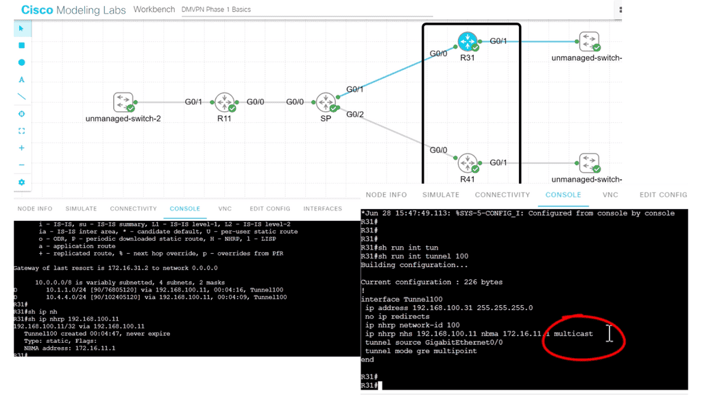
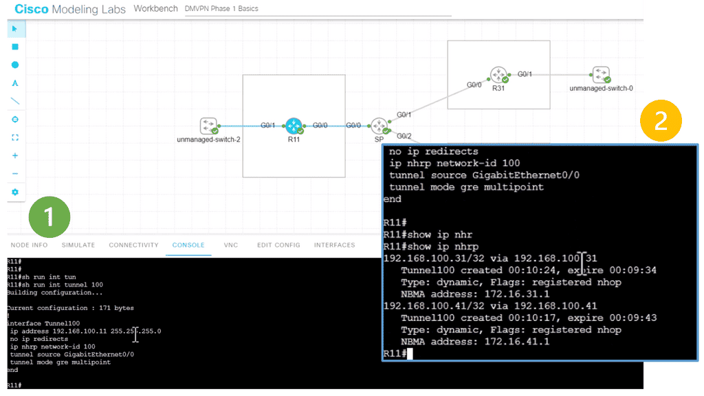
In the following lab topology, we have R11 as the hub with two spokes, R31 and R41. The spokes need to explicitly configure the next hop server (NHS) information with the command: IP nhrp NHS 192.168.100.11 nbma 172.16.11.1. Notice we have the “multicast” keyword at the end of the configuration line. This is used to allow multicast traffic.
As the routing protocol over the DMVPN tunnel, I am running EIGRP, which requires multicast Hellos to form EIGRP neighbor relationships. To form neighbor relationships with BGP, you use TCP, so you would not need the “multicast” keyword.
IPsec tunnel protection and IPsec fault tolerance: DMVPN is a routing technique not directly related to encryption. IPsec is optional and used primarily over public networks. Potential designs exist for DMVPN in public networks with GETVPN, which allows the grouping of tunnels to a single Security Association ( SA ).
Routing: Designers are implementing DMVPN without IPsec for MPLS-based networks to improve convergence as DMVPN acts independently of service provider routing policy. The sites only need IP connectivity to each other to form a DMVPN network. It would be best to ping the tunnel endpoints and route IP between the sites. End customers decide on the routing policy, not the service provider, offering more flexibility than sites connected by MPLS. MPLS-connected sites, the service provider determines routing protocol policies.
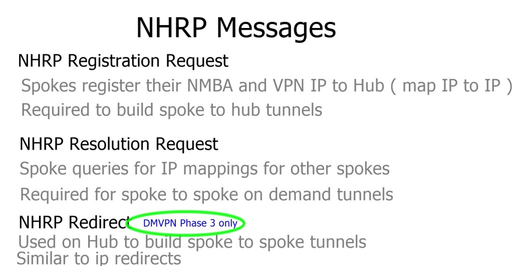
Map IP to IP: If you want to reach my private address, you need to GRE encapsulate it and send it to my public address. Spoke registration process.
DMVPN Phases Explained
DMVPN Phases: DMVPN phase 1 2 3
The DMVPN phase selected influence spoke-to-spoke traffic patterns supported routing designs and scalability.
- DMVPN Phase 1: All traffic flows through the hub. The hub is used in the network’s control and data plane paths.
- DMVPN Phase 2: Allows spoke-to-spoke tunnels. Spoke-to-spoke communication does not need the hub in the actual data plane. Spoke-to-spoke tunnels are on-demand based on spoke traffic triggering the tunnel. Routing protocol design limitations exist. The hub is used for the control plane but, unlike phase 1, not necessarily in the data plane.
- DMVPN Phase 3: Improves scalability of Phase 2. We can use any Routing Protocol with any setup. “NHRP redirects” and “shortcuts” take care of traffic flows.
- A key point: Video on DMVPN
In the following video, we will start with the core block of DMVPN, GRE. Generic Routing Encapsulation (GRE) is a tunneling protocol developed by Cisco Systems that can encapsulate a wide variety of network layer protocols inside virtual point-to-point links or point-to-multipoint links over an Internet Protocol network.
We will then move to add the DMVPN configuration parameters. Depending on the DMVPN phase you want to implement, DMVPN can be enabled with just a few commands. Obviously, it would help if you had the underlay in place.
As you know, DMVPN operates as the overlay that lays up an existing underlay network. This demonstration will go through DMVPN Phase 1, which was the starting point of DMVPN, and we will touch on DMVPN Phase 3. We will look at the various DMVPN and NHRP configuration parameters along with the show commands.
The DMVPN Phases
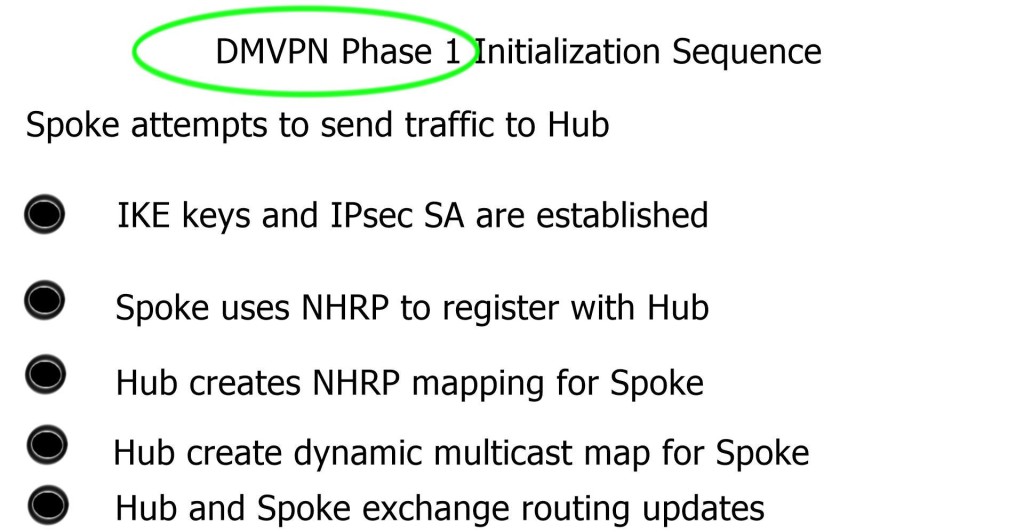
DMVPN Phase 1
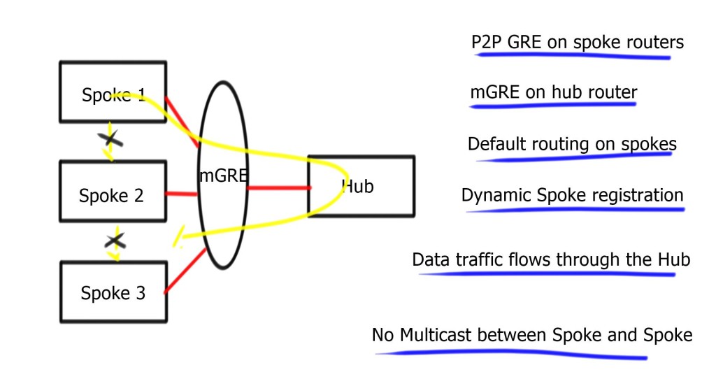
- Phase 1 consists of mGRE on the hub and point-to-point GRE tunnels on the spoke.
Hub can reach any spoke over the tunnel interface, but spokes can only go through the hub. No direct Spoke-to-Spoke. Spoke only needs to reach the hub, so a host route to the hub is required. Perfect for default route design from the hub. Design against any routing protocol, as long as you set the next hop to the hub device.
Multicast ( routing protocol control plane ) exchanged between the hub and spoke and not spoke-to-spoke.
On spoke, enter adjust MMS to help with environments where Path MTU is broken. It must be 40 bytes lower than the MTU – IP MTU 1400 & IP TCP adjust-mss 1360. In addition, it inserts the max segment size option in TCP SYN packets, so even if Path MTU does not work, at least TCP sessions are unaffected.
- A key point: Tunnel keys
Tunnel keys are optional for hubs with a single tunnel interface. They can be used for parallel tunnels, usually in conjunction with VRF-light designs. Two tunnels between the hub and spoke, the hub cannot determine which tunnel it belongs to based on destination or source IP address. Tunnel keys identify tunnels and help map incoming GRE packets to multiple tunnel interfaces.
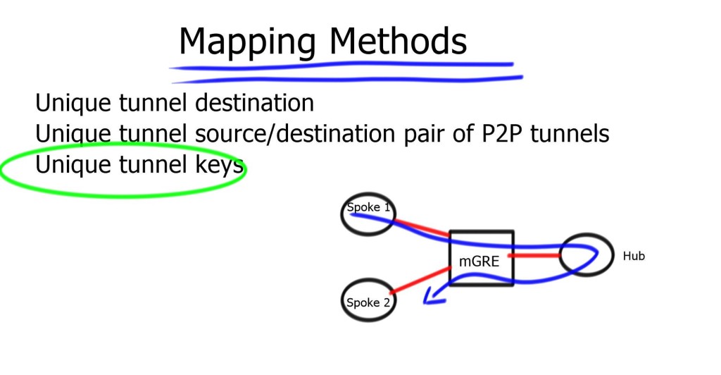
Tunnel Keys on 6500 and 7600: Hardware cannot use tunnel keys. It cannot look that deep in the packet. The CPU switches all incoming traffic, so performance goes down by 100. You should use a different source for each parallel tunnel to overcome this. If you have a static configuration and the network is stable, you could use a “hold-time” and “registration timeout” based on hours, not the 60-second default.
In carrier Ethernet and Cable networks, the spoke IP is assigned by DHCP and can change regularly. Also, in xDSL environments, PPPoE sessions can be cleared, and spokes get a new IP address. Therefore, non-Unique NHRP Registration works efficiently here.
Routing Protocol
Routing for Phase 1 is simple. Summarization and default routing at the hub are allowed. The hub constantly changes next-hop on spokes; the hub is always the next hop. Spoke needs to first communicate with the hub; sending them all the routing information makes no sense. So instead, send them a default route.
Careful with recursive routing – sometimes, the Spoke can advertise its physical address over the tunnel. Hence, the hub attempts to send a DMVPN packet to the spoke via the tunnel, resulting in tunnel flaps.
DMVPN phase 1 OSPF routing
Recommended design should use different routing protocols over DMVPN, but you can extend the OSPF domain by adding the DMVPN network into a separate OSPF Area. Possible to have one big area but with a large number of spokes; try to minimize the topology information spokes have to process.
Redundant set-up with spoke running two tunnels to redundant Hubs, i.e., Tunnel 1 to Hub 1 and Tunnel 2 to Hub 2—designed to have the tunnel interfaces in the same non-backbone area. Having them in separate areas will cause spoke to become Area Border Router ( ABR ). Every OSPF ABR must have a link to Area 0. Resulting in complex OSPF Virtual-Link configuration and additional unnecessary Shortest Path First ( SPF ) runs.
Make sure the SPF algorithm does not consume too much spoke resource. If Spoke is a high-end router with a good CPU, you do not care about SPF running on Spoke. Usually, they are low-end routers, and maintaining efficient resource levels is critical. Potentially design the DMVPN area as a stub or totally stub area. This design prevents changes (for example, prefix additions ) on the non-DVMPN part from causing full or partial SPFs.
Low-end spoke routers can handle 50 routers in single OSPF area.
Configure OSPF point-to-multipoint. Mandatory on the hub and recommended on the spoke. Spoke has GRE tunnels, by default, use OSPF point-to-point network type. Timers need to match for OSPF adjacency to come up.
OSPF is hierarchical by design and not scalable. OSPF over DMVPN is fine if you have fewer spoke sites, i.e., below 100.
DMVPN phase 1 EIGRP routing
On the hub, disable split horizon and perform summarization. Then, deploy EIGRP leak maps for redundant remote sites. Two routers connecting the DMVPN and leak maps specify which information ( routes ) can leak to each redundant spoke.
Deploy spokes as Stub routers. Without stub routing, whenever a change occurs ( prefix lost ), the hub will query all spokes for path information.
Essential to specify interface Bandwidth.
- A key point: Lab guide with DMVPN phase 1 EIGRP.
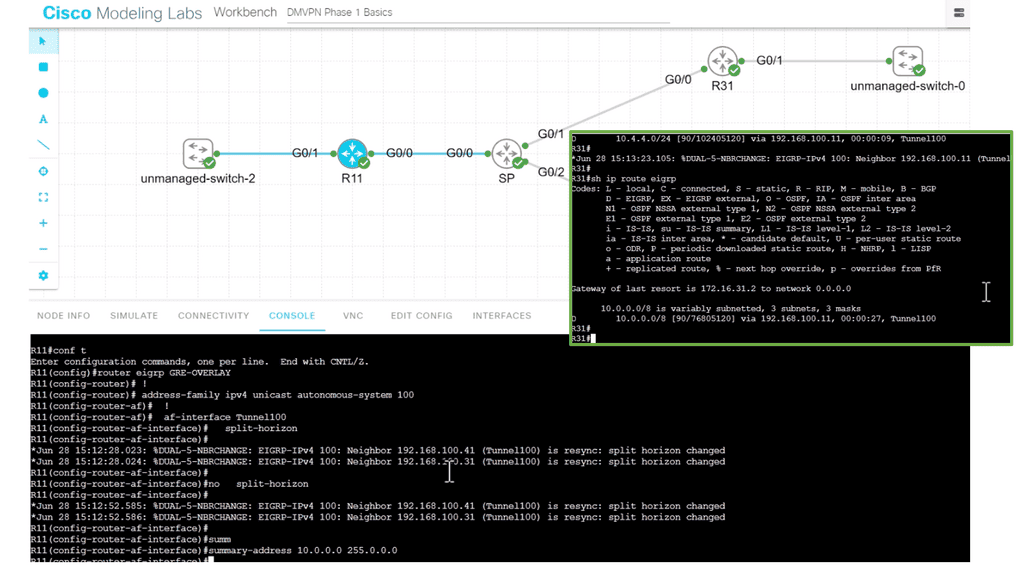
In the following lab guide, I show how to turn on and off split horizon at the hub sites, R11. So when you turn on split-horizon, the spokes will only see the routes behind R11; in this case, it’s actually only one route. They will not see routes from the other spokes. In addition, I have performed summarization on the hub site. Notice how the spoke only see the summary route.
Turning the split horizon on with summarization, too, will not affect spoke reachability as the hub summarizes the routes. So, if you are performing summarization at the hub site, you can also have split horizon turned on at the hub site, R11,
DMVPN phase 1 BGP routing
Recommended using EBGP. Hub must have next-hop-self on all BGP neighbors. To save resources and configuration steps, possible to use policy templates. Avoid routing updates to spokes by filtering BGP updates or advertising the default route to spoke devices.
In recent IOS, we have dynamic BGP neighbors. Configure the range on the hub with command BGP listens to range 192.168.0.0/24 peer-group spokes. Inbound BGP sessions are accepted if the source IP address is in the specified range of 192.168.0.0/24.
DMVPN Phase 2
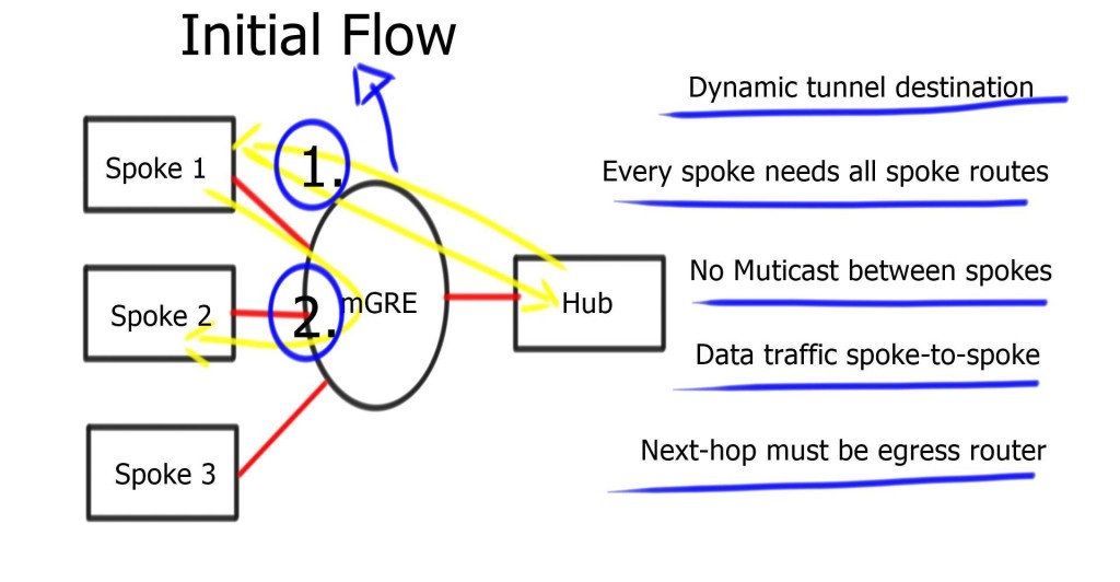
Phase 2 allowed mGRE on the hub and spoke, permitting spoke-to-spoke on-demand tunnels. Phase 2 consists of no changes on the hub router; change tunnel mode on spokes to GRE multipoint – tunnel mode gre multipoint. Tunnel keys are mandatory when multiple tunnels share the same source interface.
Multicast traffic still flows between the hub and spoke only, but data traffic can now flow from spoke to spoke.
DMVPN Packet Flows and Routing
DMVPN phase 2 packet flow
| -For initial packet flow, even though the routing table displays the spoke as the Next Hop, all packets are sent to the hub router. Shortcut not established. |
| -The spokes send NHRP requests to the Hub and ask the hub about the IP address of the other spokes. |
| -Reply is received and stored on the NHRP dynamic cache on the spoke router. |
| -Now, spokes attempt to set up IPSEC and IKE sessions with other spokes directly. |
| -Once IKE and IPSEC become operational, the NHRP entry is also operational, and the CEF table is modified so spokes can send traffic directly to spokes. |
The process is unidirectional. Reverse traffic from other spoke triggers the exact mechanism. Spokes don’t establish two unidirectional IPsec sessions; Only one.
There are more routing protocol restrictions with Phase 2 than DMVPN Phases 1 and 3. For example, summarization and default routing is NOT allowed at the hub, and the hub always preserves the next hop on spokes. Spokes need specific routes to each other networks.
DMVPN phase 2 OSPF routing
Recommended using OSPF network type Broadcast. Ensure the hub is DR. You will have a disaster if a spoke becomes a Designated Router ( DR ). For that reason, set the spoke OSPF priority to “ZERO.”
OSPF multicast packets are delivered to the hub only. Due to configured static or dynamic NHRP multicast maps, OSPF neighbor relationships only formed between the hub and spoke.
The spoke router needs all routes from all other spokes, so default routing is impossible for the hub.
DMVPN phase 2 EIGRP routing
No changes to the spoke. Add no IP next-hop-self on a hub only—Disable EIRP split-horizon on hub routers to propagate updates between spokes.
Do not use summarization; if you configure summarization on spokes, routes will not arrive in other spokes. Resulting in spoke-to-spoke traffic going to the hub.
DMVPN phase 2 BGP pouting
Remove the next-hop-self on hub routers.
Split default routing
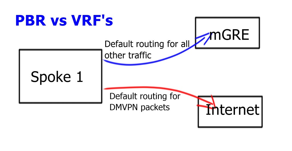
Split default routing may be used if you have the requirement for default routing to the hub: maybe for central firewall design, and you want all traffic to go there before proceeding to the Internet. However, the problem with Phase 2 allows spoke-to-spoke traffic, so even though we would default route pointing to the hub, we need the default route point to the Internet.
Require two routing perspectives; one for GRE and IPsec packets and another for data traversing the enterprise WAN. Possible to configure Policy Based Routing ( PBR ) but only as a temporary measure. PBR can run into bugs and is difficult to troubleshoot. Split routing with VRF is much cleaner. Routing tables for different VRFs may contain default routes. Routing in one VRF will not affect routing in another VRF.
Multi-homed remote site
To make it complicated, the spoke needs two 0.0.0/0. One for each DMVPN Hub network. Now, we have two default routes in the same INTERNET VRF. We need a mechanism to tell us which one to use and for which DMVPN cloud.
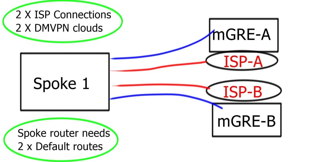
Even if the tunnel source is for mGRE-B ISP-B, the routing table could send the traffic to ISP-A. ISP-A may perform uRFC to prevent address spoofing. It results in packet drops.
The problem is that the outgoing link ( ISP-A ) selection depends on Cisco Express Forwarding ( CEF ) hashing, which you cannot influence. So, we have a problem: the outgoing packet has to use the correct outgoing link based on the source and not the destination IP address. The solution is Tunnel Route-via – Policy routing for GRE. To get this to work with IPsec, install two VRFs for each ISP.
DMVPN Phase 3
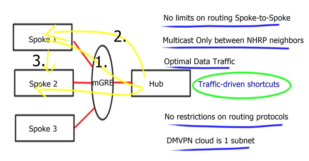
Phase 3 consists of mGRE on the hub and mGRE tunnels on the spoke. Allows spoke-to-spoke on-demand tunnels. The difference is that when the hub receives an NHRP request, it can redirect the remote spoke to tell them to update their routing table.
- A key point: Lab on DMVPN Phase 3 configuration
The following lab configuration shows an example of DMVPN Phase 3. The command: Tunnel mode gre multipoint GRE is on both the hub and the spokes. This contrasts with DMVPN Phase 1, where we must explicitly configure the tunnel destination on the spokes. Notice the command: Show IP nhrp. We have two spokes. dynamically learned via the NHRP resolution process with the flag “registered nhop.” However, this is only part of the picture for DMVPN Phase 3. We need configurations to enable dynamic spoke-to-spoke tunnels, and this is discussed next.
Phase 3 redirect features
The Phase 3 DMVPN configuration for the hub router adds the interface parameter command ip nhrp redirect on the hub router. This command checks the flow of packets on the tunnel interface and sends a redirect message to the source spoke router when it detects packets hair pinning out of the DMVPN cloud.
Hairpinning means traffic is received and sent to an interface in the same cloud (identified by the NHRP network ID). For instance, hair pinning occurs when packets come in and go out of the same tunnel interface. The Phase 3 DMVPN configuration for spoke routers uses the mGRE tunnel interface and the command ip nhrp shortcut on the tunnel interface.
Note: Placing ip nhrp shortcut and ip nhrp redirect on the same DMVPN tunnel interface has no adverse effects.
Phase 3 allows spoke-to-spoke communication even with default routing. So even though the routing table points to the hub, the traffic flows between spokes. No limits on routing; we still get spoke-to-spoke traffic flow even when you use default routes.
“Traffic-driven-redirect”; hub notices the spoke is sending data to it, and it sends a redirect back to the spoke, saying use this other spoke. Redirect informs the sender of a better path. The spoke will install this shortcut and initiate IPsec with another spoke. Use ip nhrp redirect on hub routers & ip nhrp shortcuts on spoke routers.
No restrictions on routing protocol or which routes are received by spokes. Summarization and default routing is allowed. The next hop is always the hub.
- A key point: Lab guide on DMVPN Phase 3
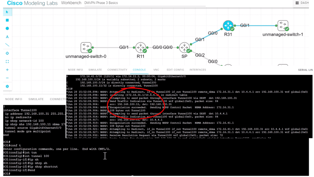
I have the command in the following lab guide: IP nhrp shortcut on the spoke, R31. I also have the “redirect” command on the hub, R11. So, we don’t see the actual command on the hub, but we do see that R11 is sending a “Traffic Indication” message to the spokes. This was sent when spoke-to-spoke traffic is initiated, informing the spokes that a better and more optimal path exists without going to the hub.
Main Checklist Points To Consider
|

