
Software Defined Internet Exchange

Software Defined Internet Exchange

In today's digital era, where data is the lifeblood of every organization, the importance of a reliable and efficient internet connection cannot be overstated. As businesses increasingly rely on cloud-based applications and services, the demand for high-performance internet connectivity has skyrocketed. To meet this growing need, a revolutionary technology known as Software Defined Internet Exchange (SD-IX) has emerged as a game-changer in the networking world. In this blog post, we will delve into the concept of SD-IX, its benefits, and its potential to revolutionize how we connect to the internet.

Software Defined Internet Exchange, or SD-IX, allows organizations to dynamically connect to multiple Internet service providers (ISPs) through a centralized platform. Traditionally, internet traffic is exchanged through physical interconnections between ISPs, resulting in limited flexibility and control. SD-IX eliminates these limitations by virtualizing the interconnection process, enabling organizations to establish direct, secure, and scalable connections with multiple ISPs.

SD-IX Defined: Software Defined Internet Exchange, or SD-IX, is a cutting-edge technology that enables dynamic and automated interconnection between networks. Unlike traditional methods that rely on physical infrastructure, SD-IX leverages software-defined networking (SDN) principles to create virtualized interconnections, providing flexibility, scalability, and enhanced control.

Enhanced Performance: One of the prominent advantages of SD-IX is its ability to optimize network performance. By utilizing intelligent routing algorithms and traffic engineering techniques, SD-IX reduces latency, improves packet delivery, and enhances overall network efficiency. This translates into faster and more reliable connectivity for businesses and end-users alike.

Flexibility and Scalability: SD-IX offers unparalleled flexibility and scalability. With its virtualized nature, organizations can easily adjust their network connections, add or remove services, and scale their infrastructure as needed. This agility empowers businesses to adapt to changing demands, optimize their network resources, and accelerate their digital transformation initiatives.

Cost Efficiency: By leveraging SD-IX, organizations can significantly reduce their network costs. Traditional methods often require expensive physical interconnections and complex configurations. SD-IX eliminates the need for such costly infrastructure, replacing it with virtualized interconnections that can be provisioned and managed efficiently. This cost-saving aspect makes SD-IX an attractive option for businesses of all sizes.

Driving Innovation: SD-IX is poised to drive innovation in the networking landscape. Its ability to seamlessly connect disparate networks, whether cloud providers, content delivery networks, or internet service providers, opens up new possibilities for collaboration and integration. This interconnected ecosystem paves the way for novel services, improved user experiences, and accelerated digital innovation.

Enabling Edge Computing: As the demand for low-latency applications and services grows, SD-IX plays a crucial role in enabling edge computing. By bringing data centers closer to the edge, SD-IX reduces latency and enhances the performance of latency-sensitive applications. This empowers businesses to leverage emerging technologies like IoT, AI, and real-time analytics, unlocking new opportunities and use cases.

Software Defined Internet Exchange (SD-IX) represents a significant leap forward in the world of connectivity. With its virtualized interconnections, enhanced performance, flexibility, and cost efficiency, SD-IX is poised to reshape the networking landscape. As organizations strive to meet the ever-increasing demands of a digitally connected world, embracing SD-IX can unlock new realms of possibilities and propel them towards a future of seamless connectivity.

SD-IX / SDX · INTERACTIVE LAB 01

How Does a Software-Defined Internet Exchange Change the Path?

Compare a conventional IXP fabric with a software-defined exchange. Follow the separation between BGP route exchange, the switching fabric and programmable traffic policy.

Internet Exchange Fabric READY
AS
Network A Member AS
IX
Exchange Fabric Shared switching fabric with BGP route exchange
BGP / Routing Control
AS
Network B Member AS
The exchange currently uses destination-based routing as the primary forwarding model.
Control Plane BGP
Data Plane L2 Fabric
Policy Granularity Prefix
Steering Limited
Conceptual model. Modern IXPs can use a variety of architectures, route servers, routing policies and programmable platforms. SDX is presented here as an architectural pattern rather than a claim that every IXP uses one specific controller or forwarding technology.
Exchange Result
Configure the exchange model and trace the traffic path.
Control-Plane Console
[READY] Awaiting exchange-path trace...
Engineering Insight

Traditional BGP-based exchange routing is powerful and scalable, but its normal decision model is centred on destination prefixes. A programmable exchange can introduce additional policy layers closer to the forwarding plane.

Highlights: Software Defined Internet Exchange

Understanding Software-Defined Internet Exchange

a) SD-IX is a cutting-edge technology that enables dynamic and flexible interconnection between networks. Unlike traditional internet exchange points (IXPs), SD-IX leverages software-defined networking (SDN) principles to create virtualized exchange environments. By abstracting the physical infrastructure, SD-IX allows on-demand network connections, enhanced scalability, and simplified network management.

b) Internet exchanges are physical locations where multiple Internet service providers (ISPs), content delivery networks (CDNs), and network operators connect their networks to exchange Internet traffic. By establishing direct connections, IXPs enable efficient and cost-effective data transfer between various networks, enhancing internet performance and reducing latency.

**How Internet Exchanges Work**

Internet Exchanges typically consist of high-speed switches and routers deployed in data centers. These devices provide the necessary connectivity between participating networks, facilitating traffic exchange.

To join an Internet Exchange, networks must adhere to specific peering policies and agreements. These guidelines dictate the terms of traffic exchange, including technical requirements, traffic ratios, and network security measures.

**Internet Exchange Points Around the World**

1: – ) Numerous Internet Exchange Points (IXPs) are located worldwide, with some of the most prominent ones including DE-CIX in Frankfurt, AMS-IX in Amsterdam, and LINX in London. These IXPs are critical hubs for global internet connectivity, enabling networks from different regions to exchange traffic.

2: – ) major global IXPs, regional and national Internet Exchange Points cater to specific geographic areas. These local IXPs further improve network performance by facilitating regional traffic exchange and reducing the need for long-haul data transfer.

3: – ) the demand for high-performance and reliable internet connectivity continues to grow, SD-IX is poised to play a pivotal role in shaping the future of networking. By virtualizing the interconnection process and providing organizations with unprecedented control and flexibility over their network connections, SD-IX empowers businesses to optimize their network performance, enhance security, and reduce costs. With its ability to scale on-demand and seamlessly reroute traffic, SD-IX is well-suited for the evolving needs of cloud-based applications, IoT devices, and emerging technologies such as edge computing.

4: – ) Defined Internet Exchange represents a paradigm shift in how organizations connect to the Internet. By virtualizing the interconnection process and providing enhanced performance, reliability, cost efficiency, scalability, and security, SD-IX offers a compelling solution for businesses seeking to optimize their network infrastructure. As the digital landscape continues to evolve, SD-IX is set to revolutionize the way we connect to the internet, enabling organizations to stay ahead of the curve and unlock new possibilities in the digital era.

Key SD-IX Considerations:

– Enhanced Performance and Latency Reduction: SD-IX brings networks closer to end-users by establishing globally distributed points of presence (PoPs). This proximity reduces latency and improves application performance, resulting in a superior user experience.

– Seamless Network Scalability: With SD-IX, organizations can quickly scale their network resources up or down based on demand. This agility empowers businesses to adapt rapidly to changing network requirements, ensuring optimal performance and cost-efficiency.

– Simplified Network Management: Traditional IXPs often require complex physical infrastructure and manual configurations. SD-IX simplifies network management by providing a centralized control plane, allowing administrators to automate provisioning, traffic engineering, and policy enforcement.

– Cloud Service Providers: SD-IX enables providers to establish direct and secure customer connections. This direct access bypasses the public internet, ensuring better security, lower latency, and improved data transfer speeds.

– Content Delivery Networks (CDNs): CDNs can leverage SD-IX to optimize content delivery by strategically placing their PoPs closer to end-users. This reduces latency, minimizes bandwidth costs, and enhances content delivery performance.

– Enterprises and Multi-Cloud Connectivity: Enterprises can benefit from SD-IX by establishing private connections between their networks and multiple cloud service providers. This enables secure, high-performance multi-cloud connectivity, facilitating seamless data transfer and workload migration.

Understanding SD-IX

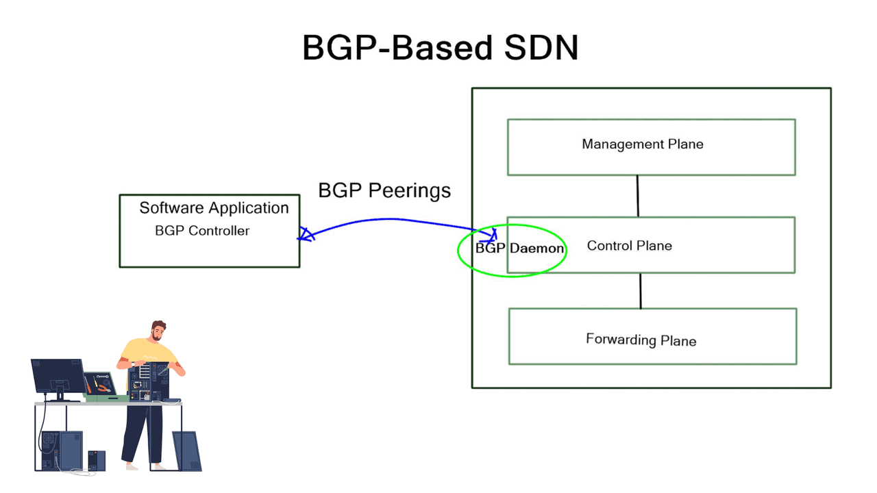
At its core, SD-IX is an architectural framework enabling the dynamic and automated internet traffic exchange between networks. Unlike traditional methods that rely on physical infrastructure, SD-IX leverages software-defined networking (SDN) principles to create a virtualized exchange ecosystem. By decoupling the control plane from the data plane, SD-IX brings flexibility, agility, and scalability to internet exchange.

One of SD-IX’s critical advantages is its ability to provide enhanced performance through optimized routing. By leveraging intelligent algorithms and real-time analytics, SD-IX can intelligently direct traffic along the most efficient paths, reducing latency and improving overall network performance. Moreover, SD-IX offers improved scalability, allowing networks to dynamically adjust their capacity based on demand, ensuring seamless connectivity even during peak usage.

Security and Privacy Advancements

SD-IX brings significant advancements in an era where data security and privacy are of the utmost concern. With the ability to implement granular access control policies and encryption mechanisms, SD-IX ensures secure data transmission across networks. SD-IX’s centralized management and monitoring capabilities enable network administrators to detect and mitigate potential security threats in real-time, bolstering overall network security.

Software-defined networks

A software-defined network (SDN) optimizes and simplifies network operations by closely tying applications and network services, whether real or virtual. By establishing a logically centralized network control point (typically an SDN controller), the control point orchestrates, mediates, and facilitates communication between applications that wish to interact with network elements and network elements that want to communicate information with those applications. The controller exposes and abstracts network functions and operations through modern, application-friendly, bidirectional programmatic interfaces.

As a result, software-defined, software-driven, and programmable networks have a rich and complex history and various challenges and solutions to those challenges. Because of the success of technologies that preceded them, software-defined, software-driven, and programmable networks are now possible.IP, BGP, MPLS, and Ethernet are the fundamental elements of most networks worldwide.

Control and Data Plane Separation

SDN’s early proponents advocated separating a network device’s control and data planes as a potential advantage. Network operators benefit from this separation regarding centralized or semi-centralized programmatic control. As well as being economically advantageous, it can consolidate into a few places, usually a complex piece of software to configure and control, onto less expensive, so-called commodity hardware.

One of SDN’s most controversial tenets is separating control and data planes. It’s not a new concept, but the contemporary way of thinking puts a twist on it: how far should the control plane be from the data plane, how many instances are needed for resiliency and high availability, and if 100% of the control plane can be moved beyond a few inches are all intensely debated. There are many possible control planes, ranging from the simplest, the fully distributed, to the semi- and logically centralized, to the strictly centralized.

OpenFlow Matching

With OpenFlow, the forwarding path is determined more precisely (matching fields in the packet) than traditional routing protocols because the tables OpenFlow supports more than just the destination address. Using the source address to determine the next routing hop is similar to the granularity offered by PBR.

In the same way that OpenFlow would do many years later, PBR permits network administrators to forward traffic based on “nontraditional” attributes, such as the source address of a packet. However, PBR-forwarded traffic took quite some time for network vendors to offer equivalent performance, and the final result was very vendor-specific.

Example Technology: Policy Based Routing

**How Policy-Based Routing Works**

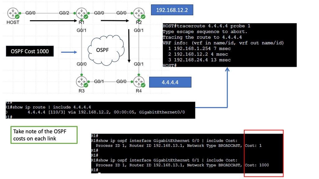
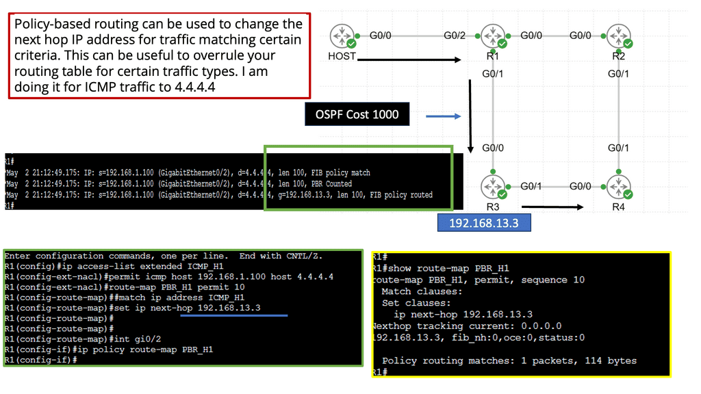
At its core, policy-based routing operates by applying a series of rules to incoming packets. These rules, defined by network administrators, determine the next hop for packets based on criteria such as source or destination IP address, protocol type, or even application-level data. Unlike conventional routing protocols that rely solely on destination IP addresses to make decisions, PBR provides the ability to consider a broader set of parameters, thus enabling more granular control over network traffic flows.

**Benefits of Implementing Policy-Based Routing**

One of the primary advantages of PBR is its ability to optimize network performance. By directing traffic along paths that make the most sense for specific types of data, network operators can reduce congestion and improve response times. Additionally, PBR can enhance security by allowing sensitive data to be routed over secure, encrypted pathways while less critical data takes a different route. This capability is particularly valuable in environments where network resources are shared across multiple departments or where specific compliance requirements must be met.

**Challenges and Considerations**

Despite its benefits, policy-based routing is not without challenges. The complexity of configuring and maintaining PBR rules can be daunting, especially in large networks with diverse requirements. Careful planning and ongoing management are essential to ensure that PBR implementations remain effective and do not introduce unintended routing behaviors. Moreover, network administrators must keep an eye on the broader network architecture to ensure that PBR policies align with overall network goals and do not conflict with other routing protocols in use.

**Use Cases: Real-World Applications of Policy-Based Routing**

Policy-based routing finds its place in a variety of real-world applications. In enterprise networks, PBR is often used to prioritize business-critical applications or to implement cost-saving measures by routing traffic over less expensive links when possible. It also plays a significant role in multi-tenant environments, where different customers or departments may require distinct levels of service. Additionally, PBR is instrumental in hybrid cloud environments, where data flows between on-premises infrastructure and cloud services must be managed efficiently.
**The Role of SDN Solutions**

Most existing SDN solutions are aimed at cellular core networks, enterprises, and the data center. However, at the WAN edge, SD-WAN and WAN SDN are leading a solid path, with many companies offering a BGP SDN solution augmenting natural Border Gateway Protocol (BGP) IP forwarding behavior with a controller architecture, optimizing both inbound and outbound Internet-bound traffic. So, how can we use these existing SDN mechanisms to enhance BGP for interdomain routing at Internet Exchange Points (IXP)?

**The Role of IXPs**

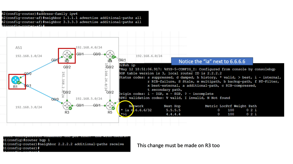
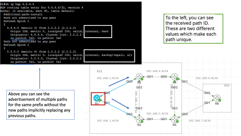
IXPs are location points where networks from multiple providers meet to exchange traffic with BGP routing. Each participating AS exchanges BGP routes by peering eBGP with a BGP route server, which directs traffic to another network ASes over a shared Layer 2 fabric. The shared Layer 2 fabric provides the data plane forwarding of packets. The actual BGP route server is the control plane to exchange routing information.

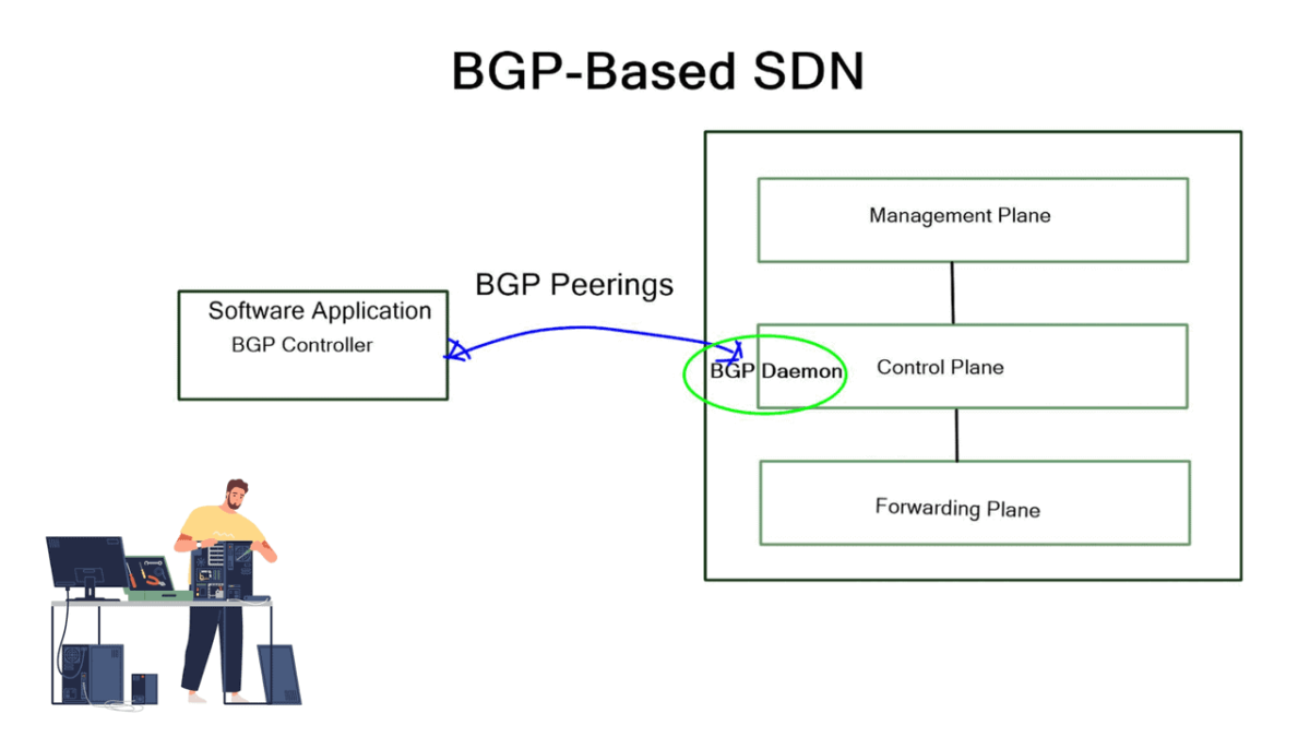
  1.  
SD-IX / SDX · INTERACTIVE LAB 02

What Can BGP Control — and What Needs a Programmable Policy?

Experiment with different traffic-engineering objectives and control mechanisms. See how destination-prefix routing differs from policies that can consider additional packet attributes.

Policy Compilation Path READY
PKT
Traffic Flow Destination prefix
POL
Policy Engine BGP route policy
FAB
IXP Fabric Forwarding decision
Available Match Fields Destination
Destination
Source
Protocol
Port
Application
Select a traffic objective and policy mechanism, then evaluate the design.
Policy Match Prefix
Path Choice Not Evaluated
Granularity Destination
Control Fit —
BGP Excellent for scalable inter-domain reachability and destination-prefix policy.
PBR Can introduce additional match criteria, but deployment and scale depend heavily on the network design.
SDX Adds a programmable policy layer capable of compiling richer traffic rules into the exchange fabric.
Conceptual simulation. The exact match fields, controller model, route-server behaviour and forwarding capabilities vary between implementations. This lab illustrates the architectural distinction rather than a specific SDX product.
Policy Evaluation
Awaiting evaluation...
Control-Plane Console
[READY] Policy engine awaiting input...
Engineering Insight

BGP is intentionally powerful at what it does: exchanging reachability information and selecting paths toward destination prefixes. More granular traffic steering requires additional mechanisms.

Software Defined Internet Exchange

An Internet exchange point (IXP) is a physical location through which Internet infrastructure companies such as Internet Service Providers (ISPs) and CDNs connect. These locations exist on the “edge” of different networks and allow network providers to share transit outside their network.

IXPs will run BGP.  Also, it is essential to understand that Internet exchange point participants often require that the BGP NEXT_HOP specified in UPDATE messages be that of the peer’s IP address, as a matter of policy.

Route Server

A route server provides an alternative to full eBGP peering between participating AS members, enabling network traffic engineering. It’s a control plane device and does not participate in data plane forwarding. There are currently around 300 IXPs worldwide. Because of their simple architecture and flat networks, IXPs are good locations to deploy SDN.

There is no routing for forwarding, so there is a huge need for innovation. They usually consist of small teams, making innovation easy to introduce. Fear is one of the primary emotions that prohibit innovation, and one thing that creates fear is Loss of Service.

This is significant for IXP networks, as they may have over 5 Terabytes of traffic per second. IXPs are major connecting points, and a slight outage can have a significant ripple effect.

  • A key point. Internet Exchange Design

SDX, a software-defined internet exchange, is an SDN solution based on the combined efforts of Princeton and UC Berkeley. It aims to address IXP pain points (listed below) by deploying additional SDN controllers and OpenFlow-enabled switches. It doesn’t try to replace the entire classical IXP architecture with something new but rather augments existing designs with a controller-based solution, enhancing IXP traffic engineering capabilities. However, the risks associated with open-source dependencies shouldn’t be ignored.

Challenges: Software Defined Internet Exchange: IXP Pain Points

BGP is great for scalability and reducing complexity but severely limits how networks deliver traffic over the Internet. One tricky thing to do with BGP is good inbound TE. The issue is that IP routing is destination-based, so your neighbor decides where traffic enters the network. It’s not your decision.

The forwarding mechanism is based on the destination IP prefix. A device forwards all packets with the same destination address to the same next hop, and the connected neighbor decides.

The main pain points for IXP networks:

As already mentioned, routing is based on the destination IP prefix. BGP selects and exports routes for destination prefixes only. It doesn’t match other criteria in the packet header, such as source IP address or port number. Therefore, it cannot help with application steering, which would be helpful in IXP networks.

Secondly, you can only influence direct neighbors. There is no end-to-end control, and it’s hard to influence neighbors that you are not peering. Some BGP attributes don’t carry across multiple ASes; others may be recognized differently among vendors. We also use a lot of de-aggregation to TE. Everyone is doing this, which is why we have the problem of 540,000 prefixes on the Internet. De-aggregation and multihoming create lots of scalability challenges.

Finally, there is an indirect expression of policy. Local Preference (LP) and Multiple Exit Discriminator (MED) are ineffective mechanisms influencing traffic engineering. We should have better inbound and outbound TE capabilities. MED, AS Path, pretending, and Local Preference are widely used attributes for TE, but they are not the ultimate solution.

They are inflexible because they can only influence routing decisions based on destination prefixes. You can not do source IP or application type. They are very complex, involving intense configuration on multiple network devices. All these solutions involve influencing the remote party to decide how it enters your AS, and if the remote party does not apply them correctly, TE becomes unpredictable.

SDX: Software-Defined Internet Exchange

The SDX solution proposed by Laurent is a Software-Defined Internet Exchange. As previously mentioned, it consists of a controller-based architecture with OpenFlow 1.3-enabled physical switches. It aims to solve the pain points of BGP at the edge using SDN.

Transport SDN offers direct control over packet-processing rules that match on multiple header fields (not just destination prefixes) and perform various actions (not just forwarding), offering direct control over the data path. SDN enables the network to execute a broader range of decisions concerning end-to-end traffic delivery.

How does it work?

What is OpenFlow? Is the IXP fabric replaced with OpenFlow-enabled switches? Now, network traffic engineering is based on granular OpenFlow rules. It’s more predictable as it does not rely on third-party neighbors to decide the entry. OpenFlow rules can be based on any packet header field, so they’re much more flexible than existing TE mechanisms. An SDN-enabled data plane enables networks to have optimal WAN traffic with application steering capabilities. 

The existing route server has not been modified, but now we can push SDN rules into the fabric without requiring classical BGP tricks (local preference, MED, AS prepend). The solution matches the destination MAC address, not the destination IP prefix, and uses an ARP proxy to convert the IP prefixes to MAC addresses.

The participants define the forwarding policies, and the controller’s role is to compile the forwarding entries into the fabric. The SDX controller implementation has two main pipelines: a policy compiler based on Pyretic and a route server based on ExaBGP. The policy compiler accepts input policies (custom route advertisements) written in Pyretic from individual participants and BGP routes from the route server. This produces forwarding rules that implement the policies.

SDX Controller

The SDX controller combines the policies from multiple member ASes into one policy for the physical switch implementation. The controller is like an optimized compiler, compiling down the policy and optimizing the code in the forwarding by using a virtual next hop. There are other potential design alternatives to SDX, such as BGP FlowSpec. But in this case, BGP FlowSpec would have to be supported by all participating member AS edge devices.

Closing Points on Software Defined Internet Exchange

At its core, SDX is an evolution of traditional Internet Exchange Points (IXPs), which are critical nodes in the internet’s infrastructure, allowing different networks to interconnect. Traditional IXPs are hardware-driven, requiring physical switches and routers to manage traffic between networks. SDX, on the other hand, leverages the principles of SDN to introduce a software layer that enhances flexibility and control over these exchanges. This software-defined approach allows for dynamic configuration and management of network policies, enabling more efficient and tailored data traffic handling.

One of the primary benefits of SDX is its capacity for greater agility and adaptability in managing network traffic. Unlike traditional IXPs, SDX can quickly respond to changing network demands, optimizing the flow of data in real time. This adaptability is particularly beneficial for handling peak traffic periods or unexpected surges, ensuring that data exchanges remain smooth and uninterrupted. Additionally, SDX provides enhanced security features, as the software layer can be programmed to detect and mitigate potential threats more effectively than conventional hardware solutions.*

The implications of adopting SDX are vast and varied. For internet service providers, SDX offers the potential to provide more personalized services to their customers, adjusting bandwidth and routing protocols based on individual needs. Enterprises can benefit from SDX by gaining more control over their data exchanges, optimizing their network performance, and reducing operational costs. Furthermore, SDX is particularly advantageous for emerging technologies like the Internet of Things (IoT) and 5G networks, where the ability to efficiently handle large volumes of data is crucial.

Despite its many advantages, the transition to SDX is not without its challenges. Implementing SDX requires significant changes to existing network infrastructures, which can be costly and complex. Moreover, the shift to a software-centric model necessitates a new skill set for IT professionals, who must be adept in both networking and software development. There is also the consideration of interoperability, as networks must ensure that their SDX solutions can work seamlessly with other networks and legacy systems.

SD-IX / SDX · INCIDENT CHALLENGE

SDX Traffic Engineering Challenge

A customer wants only one class of traffic to use a different exchange path. Can conventional BGP policy solve the requirement, or does the problem need a more granular traffic-steering layer?

!
Incident: Video Traffic Is Taking the Wrong Exit AS65010 has two exchange paths. Peer A is congested, while Peer B has available capacity. General routing remains healthy, but the customer wants only video traffic to prefer Peer B.
AS65010 Customer Network
→
Peer A Congested · 92%
or
Peer B Healthy · 38%
→
Destination Content Network
BGP Sessions Established
Reachability Healthy
Peer A Congested
Peer B Available
Requirement Video Only
What is the best engineering response?
Challenge Score
Result — / 4
Select the response you believe best matches the evidence.
Incident Console
[READY] Incident loaded.
[BGP] Peer sessions established.
[PATH] Multiple exchange paths available.
[ALERT] Peer A congestion detected.
Engineering Insight

The important clue is “video only.” A global routing preference may affect more traffic than intended. The engineering challenge is therefore one of policy granularity, not basic reachability.

BGP FlowSpec

Network Engineering Guide · BGP Security · Traffic Control

BGP FlowSpec enables networks to distribute traffic-filtering and traffic-treatment rules through BGP, helping engineers respond to specific traffic patterns without relying solely on destination-based routing changes.

During a denial-of-service attack or other disruptive traffic event, changing a destination route may be too broad to address the problem. FlowSpec provides a more granular approach: a controller or routing system can distribute rules that match supported traffic characteristics and apply actions supported by the receiving platform.

But receiving a rule is not the same as enforcing it. Engineers must establish whether the policy was accepted, installed at the intended enforcement point, matched the relevant packets, and produced the expected result. They must also check that legitimate traffic remains available and that the response does not create a new operational problem.

This guide takes an engineering-led approach to FlowSpec, moving from policy architecture and visibility through incident diagnosis to remediation and verification. The interactive exercises let you change policy choices, examine evidence, and investigate why an apparently valid rule may fail to affect traffic.

01 · SEE Understand the architecture Follow how a FlowSpec rule is constructed, distributed, and intended to reach an enforcement point.
02 · OBSERVE Examine the evidence Compare policy state, traffic measurements, and enforcement visibility.
03 · INVESTIGATE Isolate the failure Use incident evidence to distinguish distribution, validation, installation, and matching problems.
04 · CORRELATE Verify the outcome Connect routing and forwarding evidence, apply a justified correction, and confirm recovery.
The central engineering question

Can you prove that the intended FlowSpec rule reached the correct enforcement point, matched the intended traffic, and produced the expected outcome without unnecessarily disrupting legitimate services?

Engineering Preview · 01 / Architecture

Follow a FlowSpec Rule Through the Network

A FlowSpec rule has to move from policy definition through BGP distribution and validation before the receiving platform can enforce it. Select a stage to see what the engineer should verify.

**Define:** Identify the traffic pattern, match fields and intended action. Start with evidence, not a broad guess.
Section 01 · See the system

BGP FlowSpec Architecture and Policy Distribution

BGP FlowSpec extends BGP beyond conventional route-prefix advertisement. It allows supported traffic-matching rules and associated actions to be distributed to participating routers, creating a control-plane mechanism for coordinating more granular traffic treatment.

The key architectural distinction is between the control plane, which distributes and processes policy, and the data plane, which evaluates packets against installed forwarding rules. A rule can appear in BGP without being successfully installed or enforced in hardware or software. Understanding that separation is essential when designing a FlowSpec deployment or investigating an incident.

1.1 The FlowSpec policy lifecycle

A typical deployment starts with a traffic event or a policy decision. A controller or authorised routing process creates a FlowSpec NLRI describing the traffic to match and associates it with supported actions. BGP distributes the rule to eligible peers, where import policy, validation, platform capabilities, and forwarding resources determine whether it can be used.

STAGE 01 Define the flow

Identify the relevant traffic characteristics and construct a rule with an appropriate scope.

STAGE 02 Distribute through BGP

Advertise the FlowSpec NLRI to eligible peers under the configured routing policy.

STAGE 03 Validate and install

Evaluate acceptance, validation, supported actions, and forwarding-resource constraints.

STAGE 04 Enforce and verify

Confirm the intended packets are affected and service behaviour matches expectations.

Engineering principle BGP distribution proves that a control-plane exchange occurred. It does not, by itself, prove that the receiving router installed the rule or that packets matched it.

1.2 The main architectural components

FlowSpec controller or policy origin

The origin creates or selects the rule based on a security event, operational decision, or traffic-analysis result. In a production design, its permissions, input validation, and policy-generation process should be controlled and auditable.

BGP speakers and route reflectors

BGP peers carry FlowSpec NLRI between participating systems. Route reflectors may help distribute eligible routes across an iBGP topology, but their behaviour depends on platform support and configuration. Ordinary route-reflection assumptions should not replace FlowSpec-specific verification.

Policy validation and import controls

Receiving routers may apply import policy, origin and route validation checks, rule-consistency checks, and deployment-specific restrictions. A session being Established does not guarantee that every advertised FlowSpec rule will be accepted.

Forwarding enforcement point

The router that actually handles the traffic must translate an accepted rule into a supported forwarding or filtering action. Hardware table capacity, software support, resource limits, and the actual traffic path can all affect the result.

1.3 What does a FlowSpec rule describe?

A FlowSpec rule identifies a class of traffic using supported match components. Depending on the address family, implementation, and negotiated capabilities, these can include source or destination prefixes, IP protocol, ports, TCP flags, ICMP fields, packet length, and other defined traffic characteristics.

The rule is associated with one or more actions, such as discarding matching packets or applying a supported rate limit. Other actions and combinations may be available on particular platforms, but engineers must verify the implementation rather than assume universal support. Match specificity, rule precedence, and interactions with existing policy also require careful consideration.

Design element Engineering question Evidence to inspect
Match components Does the rule describe the unwanted traffic precisely enough? Advertised NLRI, decoded match fields, and observed packet characteristics.
Policy distribution Did the intended routers receive the rule? BGP peer state, received FlowSpec entries, and import-policy results.
Acceptance and installation Was the rule accepted and programmed for enforcement? Validation results, installed-policy tables, platform logs, and resource status.
Traffic outcome Did the rule affect the intended traffic without unacceptable side effects? Traffic rates, counters, packet observations, and service-health measurements.

1.4 FlowSpec is not the same as changing a destination route

Conventional BGP route advertisements primarily describe reachability to destination prefixes. FlowSpec distributes traffic classification and treatment rules. It can therefore target selected traffic without necessarily changing the destination prefix's best path in the routing table.

This distinction matters during incident response. A FlowSpec rule might be distributed correctly but fail to affect traffic because the rule is not installed, the match does not describe the actual packets, or the traffic does not traverse the intended enforcement point. Changing an unrelated destination route may not solve any of those problems.

Section 1 takeaway Treat FlowSpec as a complete policy lifecycle—not simply a BGP advertisement. Follow the rule from its origin through distribution and validation to forwarding installation, then verify its effect on real traffic.

Implementation note: FlowSpec support, validation behaviour, supported actions, precedence, and forwarding-resource limits vary across network operating systems and hardware. Confirm the relevant platform documentation before applying these concepts to a production network.

Network Insight · Interactive Engineering Lab 01

How Does a FlowSpec Policy Reach the Forwarding Plane?

Trace a conceptual FlowSpec rule from policy origin through BGP distribution, receiver validation and installation. Step through the evidence and see where the process can stop.
Ready to investigate
FlowSpec Control and Enforcement Path
0 / 7 stages
◈
POLICY ORIGIN
Controller / BGP speaker
Not originated
⇄
BGP DISTRIBUTION
RR / BGP peers
Waiting
▤
ENFORCEMENT EDGE
Receiver · FlowSpec
Waiting
Illustrative match: TCP · SYN traffic · destination service
Proposed action: Rate-limit matching traffic
Distribution target: One intended edge receiver
Architecture principle: FlowSpec distributes traffic-match and action information through BGP. The receiving platform must still accept and install the policy before enforcement can be confirmed.
Policy Specification
Illustrative
Match criteria
Protocol: TCP
TCP flags: SYN
Destination: protected service
Action
Rate-limit matching packets
Platform support required
Rule originConfigured policy speaker
Receiver scopeSingle edge
AcceptanceNot evaluated
InstallationNot evaluated
Receiver Evidence
Simulated state
BGP sessionEstablished
Rule receivedNo
Policy acceptedPending
Forwarding stateNot installed
Traffic outcomeNot measured
Policy Lifecycle Trace
Select Step Forward
01
Originate
The policy origin defines the FlowSpec match and intended action.
02
Encode
The speaker constructs a FlowSpec NLRI and associated path attributes.
03
Distribute
BGP advertises the policy to eligible peers and configured receivers.
04
Receive
The intended receiver processes the update and evaluates its policy controls.
05
Validate
The receiver evaluates acceptance and validation requirements.
06
Install
The platform attempts to install the accepted rule for enforcement.
07
Verify
The engineer checks installation evidence and measures the traffic outcome.
Live Engineering Readout
Evidence-led
Current Stage
Ready to begin
Step through the lifecycle to follow the rule and distinguish BGP distribution from forwarding enforcement.
Lifecycle Progress
Engineering takeaway: a healthy BGP session does not prove that a FlowSpec rule has been accepted, installed or enforced.
Training model only. The topology, lifecycle and evidence are conceptual; no live BGP session or router is controlled. FlowSpec match components, actions, validation rules, forwarding installation and route-reflector behaviour depend on platform capabilities and configuration.

Engineering Preview · 02 / Observability

Where Can You Prove What Happened?

FlowSpec troubleshooting requires evidence from multiple layers. Choose a vantage point to discover what it can prove—and what it cannot prove on its own.

BGP control plane: Peer state and received NLRI show distribution progress. They do not independently prove that a forwarding rule is installed.
Section 02 · Observe the evidence

Flow Matching, Telemetry and Enforcement Evidence

A FlowSpec policy is only useful if engineers can establish what happened after the rule was created. Effective troubleshooting requires visibility across BGP distribution, policy acceptance, forwarding installation, packet matching, and the resulting traffic behaviour.

No single counter or status proves the entire chain. A BGP session can be healthy while a particular rule is rejected. A rule can appear in a received-policy table without being installed for forwarding. An installed rule can remain ineffective if its match criteria do not describe the actual traffic or if the packets take a different path.

2.1 Observe the system at multiple points

Start by dividing the policy lifecycle into observable stages. At each stage, identify the evidence available and the question it can answer. This prevents an engineer from treating a successful control-plane event as proof of a successful data-plane outcome.

01
BGP session and route reception

Check peer state, address-family negotiation, received FlowSpec entries, and relevant import-policy results. This establishes whether the distribution path is functioning for the rule under investigation.

02
Validation and accepted policy

Determine whether the rule passed the receiver's applicable validation and policy checks. Inspect the decoded NLRI and associated actions where the platform exposes them.

03
Forwarding installation

Inspect the platform's installed FlowSpec or forwarding-policy state, including any programming errors, unsupported actions, resource exhaustion, or hardware-table constraints.

04
Traffic and service outcome

Compare traffic rates, packet or policy counters where available, interface measurements, and application health before and after enforcement. Check whether legitimate traffic is also being affected.

Evidence rule Match every operational claim to the layer that can prove it. Peer state proves session health; installed-policy state provides evidence of programming; traffic measurements help establish whether the intended operational outcome occurred.

2.2 Understand what each measurement tells you

Control-plane visibility

BGP neighbour state, address-family status, received and advertised FlowSpec entries, route attributes, and policy logs help explain how a rule moved through the routing system.

Useful for: locating distribution, import-policy, and validation problems.

Forwarding-plane visibility

Installed-policy tables, supported hardware or software counters, programming logs, and resource utilisation help establish whether the intended rule is available for packet processing.

Useful for: identifying installation failures or forwarding limitations.

Traffic telemetry

Interface utilisation, packet rates, flow records, sampled traffic, and upstream or downstream measurements help characterise the event and evaluate changes after enforcement.

Useful for: determining where traffic volume changes and whether the attack pattern persists.

Service-level evidence

Application availability, latency, error rates, synthetic tests, and customer-impact indicators help establish whether the mitigation protects the service rather than simply changing a network counter.

Useful for: confirming business impact and detecting collateral damage.

2.3 Validate the match against real traffic

A rule can be syntactically valid and successfully installed yet fail to mitigate the intended event. The match may be too narrow, too broad, or based on an incorrect assumption about the traffic. Engineers should compare the FlowSpec components with observed packet or flow characteristics rather than relying only on the policy description.

Observation Possible interpretation Next verification
Rule received, but not installed Validation, policy, capability, or forwarding-resource issue. Inspect rejection reasons, platform support, and installation logs.
Rule installed, but traffic is unchanged Match mismatch, wrong enforcement point, alternate traffic path, or ineffective measurement. Compare actual packet characteristics, routing path, policy counters, and measurements on both sides of enforcement.
Traffic volume falls, but service remains unhealthy The mitigation may be incomplete, congestion may persist elsewhere, or the service may have another fault. Correlate multiple interfaces, upstream traffic, resource utilisation, and application telemetry.
Traffic falls, but legitimate requests also fail The match may be too broad or the action may be too aggressive. Review rule scope, compare legitimate traffic patterns, and validate the effect before retaining the policy.

2.4 Compare measurements from the right vantage points

A traffic measurement is meaningful only in context. An ingress interface may show the full attack volume, while an interface beyond an effective discard point may show a substantial reduction. However, measurements taken at different sampling intervals, interfaces, or traffic directions can produce misleading comparisons.

Establish a baseline, record when the policy was installed, and compare equivalent measurement windows. Where possible, inspect both sides of the enforcement point and monitor unaffected traffic or service probes as a control. This helps distinguish a genuine mitigation effect from an upstream traffic change, measurement gap, or unrelated outage.

Practical measurement sequence Record the initial traffic pattern, identify the intended enforcement point, confirm the rule's installed state, observe traffic after the change, and validate service health. If these signals disagree, investigate the discrepancy before declaring success.

2.5 Build an evidence chain, not a collection of screenshots

Useful incident evidence should be time-correlated. Capture the policy identifier or match definition, the relevant BGP state, acceptance or rejection information, installation status, traffic measurements, and service observations with timestamps. This lets another engineer reconstruct what happened and distinguish cause from coincidence.

Record the expected result before changing the policy. For example, a mitigation may be expected to reduce a particular traffic class beyond an enforcement point while keeping legitimate application probes healthy. That expectation gives the investigation a testable outcome instead of an ambiguous target such as “traffic looks better.”

Section 2 takeaway Effective FlowSpec observability connects control-plane state, forwarding installation, traffic behaviour, and service health. A rule is not proven effective until the available evidence supports the intended outcome and checks for unwanted side effects.

Telemetry availability and command output vary by platform. Counters may be absent, aggregated, sampled, or updated asynchronously. Treat each measurement according to its scope and limitations, and consult the relevant network operating system documentation.

Engineering Evidence · Lab 02 · Observe

BGP FlowSpec Visibility & Telemetry Lab

Compare what an engineer can observe at the policy origin, route reflector and enforcement edge. A healthy BGP session does not by itself prove that a policy was accepted, installed or effective.
SIMULATION READY
FlowSpec visibility mapConceptual topology
⌘
Policy Origin Rule defined and advertisedOrigin evidence
⇄
Route Reflector Distribution, if deployedDistribution evidence
◈
Enforcement Edge Validation and forwarding installSelected
BGP sessionEstablishedPeer/session evidence
Policy stateInstalledLocal enforcement evidence
Traffic rate2.1 GbpsIllustrative telemetry
Evidence matrixSignal versus state
Evidence sourceWhat it provesObserved result
Selected vantage pointEdge router

Inspect local enforcement

Confirm that the rule was received, accepted, installed and matched by traffic counters.

Ready to observe

Choose a scenario and run an observation to inspect the evidence.

Ready — select a vantage point and scenario.
Observation traceSimulated evidence
READYWaiting for observationIDLE
Engineering takeaway: Correlate BGP session state, received FlowSpec NLRI, local validation, forwarding installation, rule counters and traffic measurements. Each provides a different piece of evidence.
Training simulation only. Commands, telemetry, validation behaviour, counters and supported actions vary by vendor, software release, hardware and configuration. A route reflector is optional and represents one possible distribution design.

Engineering Preview · 03 / Investigation

A Policy Failed. Where Do You Start?

When unwanted traffic continues, avoid jumping straight to a configuration change. Select the first evidence category you would investigate.

Start with the session and received rule. Establish whether the intended receiver actually received the update before investigating later stages.
Section 03 · Investigate the failure

BGP FlowSpec Incident Investigation

When a FlowSpec mitigation fails, the fastest route to a reliable fix is to isolate the failure stage before changing configuration. A healthy BGP session, a received rule, and continuing attack traffic are important clues—but they do not, on their own, identify the root cause.

Consider an incident in which a network is experiencing a high-volume traffic surge. The FlowSpec BGP session is Established and the rule appears to have been received, yet the traffic rate remains high. The operational question is not simply whether FlowSpec is enabled; it is where the expected policy lifecycle stopped producing the intended result.

3.1 Start with impact, scope, and a timeline

Before altering the policy, establish the customer or service impact, the affected destinations and traffic classes, and the time the incident began. Compare the event timeline with policy changes, BGP updates, device alarms, interface measurements, and service-health signals.

Define the incident

Record the affected service, traffic direction, observed volume, onset time, and expected mitigation outcome. Establish whether the impact is confined to one path or affects multiple locations.

Preserve the baseline

Capture relevant routing and policy state, traffic measurements, logs, and service indicators before making changes. This provides a comparison point and helps prevent evidence from being lost during remediation.

Incident discipline Separate observed facts from hypotheses. “The BGP session is Established” is an observation. “The mitigation should therefore be working” is an assumption that still needs evidence.

3.2 Follow a fault-isolation sequence

01
Confirm distribution

Verify that the intended FlowSpec rule was advertised and received by the relevant peer. Check the correct address family, policy scope, and actual rule contents—not just the neighbour state.

02
Check acceptance and validation

Determine whether the receiving router accepted the rule under its configured import and validation behaviour. Inspect rejection reasons, route-policy decisions, and any required consistency checks.

03
Verify installation

Check whether the rule was programmed for forwarding. Investigate unsupported components or actions, resource constraints, installation errors, and differences between the accepted control-plane entry and the installed state.

04
Test the match and traffic path

Compare the rule's source, destination, protocol, ports, and other selected fields with observed traffic. Verify that the packets traverse the router where the rule is installed and that the action applies to the intended direction.

05
Measure the actual outcome

Compare equivalent pre- and post-mitigation measurements. Confirm whether the targeted traffic changes, whether congestion remains elsewhere, and whether legitimate service traffic continues to work.

3.3 Distinguish the main failure classes

Evidence observed Potential failure class Investigation priority
BGP is Established, but the expected rule is absent on the receiving router. Distribution, address-family, advertisement, or policy-scope problem. Check advertised and received entries, negotiated capabilities, and import policy.
The rule is received but rejected or unavailable for use. Validation, import-policy, or implementation restriction. Inspect the rule contents, rejection reason, validation requirements, and platform behaviour.
The rule is accepted but not installed for forwarding. Forwarding programming, unsupported feature, or resource problem. Inspect installation state, platform logs, supported actions, and resource utilisation.
The rule is installed but the targeted traffic remains unchanged. Incorrect match, unexpected traffic path, wrong enforcement point, or misleading telemetry. Compare actual packet characteristics, traffic direction, route path, and counters at the enforcement point.
Targeted traffic falls but service health remains poor. Incomplete mitigation, congestion elsewhere, or an independent service fault. Correlate upstream and downstream traffic, device health, and application measurements.

3.4 Use evidence to test competing hypotheses

A disciplined investigation avoids committing to the first plausible explanation. If a rule appears in the received FlowSpec table but is missing from the installed-policy state, prioritise acceptance and forwarding-programming evidence. If it is installed and no targeted traffic changes, investigate match accuracy and the actual traffic path before repeatedly resetting the BGP session.

Each diagnostic action should distinguish between hypotheses. Inspecting an installed-policy table may separate an installation failure from a traffic-matching problem. Comparing measurements immediately before and after the enforcement point may help determine whether packets are being treated there. Reviewing application probes may show whether the network mitigation actually restores service.

Prefer a discriminating test

Choose the next check because its result can rule a hypothesis in or out. Avoid making several unrelated configuration changes at once, as they make cause and effect harder to establish.

Respect the production risk

Use read-only checks first. Any change to a filtering policy should follow the operational change process, account for legitimate traffic, and include a rollback path appropriate to the incident.

3.5 Choose remediation based on the confirmed fault

Once the failure stage is supported by evidence, make the smallest justified correction. A distribution problem calls for a different response from an unsupported forwarding action or a rule that does not match the attack traffic. Repeatedly re-advertising the same rule will not fix every one of these conditions.

After the change, repeat the relevant checks. Confirm the updated rule is received and accepted, verify installation at the intended enforcement point, and measure both mitigation effectiveness and legitimate-service impact. If the expected result is not observed, return to the evidence chain rather than assuming the change succeeded.

Section 3 takeaway Isolate the failure before changing the network: distribution, validation, installation, matching, traffic path, and service outcome are separate diagnostic stages. The root cause should explain the evidence, and the remediation should produce a measurable, repeatable improvement.

FlowSpec validation and installation details differ by platform and configuration. Use device-specific operational commands and logs to confirm each stage; the sequence above is a vendor-neutral investigation framework, not a claim that every implementation exposes identical state.

Engineering Evidence · Lab 03

BGP FlowSpec Incident Investigation

Trace a traffic-control incident from policy origin to enforcement. Refresh the evidence, inspect the path, and identify the most likely failure stage. This is a simulated engineering exercise; real commands and platform behaviour vary by vendor.

BGP session—
FlowSpec at edge—
Forwarding state—
Observed traffic—
Waiting for evidenceChoose a scenario and press Refresh Evidence.

Choose your diagnosis

Diagnosis not submittedRefresh the evidence first, then select a likely cause.

Live policy path & enforcement

Waiting for evidence
FlowSpec OriginPolicy source
Route Reflector / PeerPropagation path
Enforcement EdgeAwaiting rule
Traffic OutcomeAwaiting counters
Refresh the incident evidence to illuminate the simulated path and show the likely failure point.

Correlated incident timeline

No observations collected
  • Choose an incident and refresh evidence.
Engineering takeaway
A healthy BGP session does not prove that a FlowSpec rule has been accepted, installed in the forwarding plane, or matched the traffic you intend to control.

Engineering Preview · 04 / Correlation

Did the Mitigation Actually Restore the Service?

Successful operations correlate the policy state with network measurements and user-facing service health. Select a verification signal to see how it contributes to the recovery decision.

Policy state: Verify the rule is accepted and installed at the intended enforcement points. This confirms policy progress, not full service recovery.
Section 04 · Correlate and operate

FlowSpec Policy Correlation, Remediation and Recovery Verification

An effective FlowSpec response requires more than a rule that appears in the routing system. Engineers must correlate control-plane events, forwarding state, traffic measurements, and service health to establish what changed, why it changed, and whether the incident is actually resolved.

Each telemetry source describes a different part of the system. BGP logs show distribution activity; installed-policy state helps establish forwarding readiness; traffic measurements describe observed network behaviour; and service probes reveal whether users can access the application. Considered together, these signals provide a stronger operational picture than any one indicator alone.

4.1 Correlate the evidence across the network

Routing and policy events

Correlate advertisements, withdrawals, neighbour events, import-policy decisions, and validation results. Establish which rule version was present at each relevant point in the incident timeline.

Forwarding and device health

Compare installed-policy state with programming errors, forwarding-resource utilisation, interface counters, and relevant device alarms. Look for evidence that the intended action became operational.

Traffic-path measurements

Compare observations at appropriate ingress and egress points. Account for routing changes, alternate paths, measurement intervals, sampling, and traffic that may bypass the enforcement router.

Application and service health

Correlate latency, availability, request errors, synthetic tests, and customer-impact signals with the network changes. Reduced traffic volume is not sufficient evidence that the service has recovered.

Correlation principle Align timestamps, identify the same policy or incident across data sources, and compare equivalent measurement windows. A change that occurred after a mitigation is evidence to investigate—not automatic proof that the mitigation caused it.

4.2 Establish a measurable success condition

Before changing a policy, define what successful mitigation means for this incident. The expected result should describe the traffic that must change, the observation point where the change should be visible, and the service condition that must remain acceptable.

Validation dimension Example success condition Evidence to collect
Policy state The intended rule is accepted and installed on the expected enforcement router. Accepted and installed policy state, validation output, and device logs.
Target traffic The unwanted traffic class is reduced or treated as intended beyond the enforcement point. Comparable traffic measurements, relevant counters, and flow observations.
Legitimate traffic Permitted traffic continues to receive the intended service. Application probes, legitimate request tests, and appropriate traffic counters.
Infrastructure health Mitigation does not introduce unacceptable device load or resource exhaustion. Forwarding-resource state, CPU or memory where relevant, and interface utilisation.
Recovery The affected service meets its agreed operational health criteria for a suitable observation period. Availability, latency, error rates, and incident-specific monitoring.

4.3 Apply a controlled remediation

Remediation should address the failure confirmed by the evidence. A rule that does not match the observed traffic needs a different correction from a rule rejected by policy or one that cannot be installed by the forwarding platform. Avoid broadening a match or applying a more aggressive action simply because the original policy did not deliver the expected result.

01
State the diagnosed fault

Document the evidence that identifies the failed stage and distinguish it from other plausible explanations.

02
Select the narrowest justified change

Correct the specific distribution, validation, installation, matching, or path issue. Consider the potential effect on legitimate traffic and other policies.

03
Plan rollback and ownership

Use the applicable change-control process, identify who is responsible for validation, and define how to withdraw or reverse the change if the outcome is unsafe.

04
Recheck the complete policy chain

Verify the updated rule, its acceptance and installation, the traffic effect, and the health of the protected service. Do not infer success from a successful configuration change alone.

4.4 Verify recovery—and know when to remove the mitigation

Once the immediate threat is controlled, continue monitoring long enough to establish that the result is stable. Check for residual attack traffic, congestion elsewhere in the network, unexpected effects on permitted flows, and any remaining application symptoms. Where the service remains unhealthy, investigate independent or downstream causes rather than assuming the FlowSpec rule is still the only issue.

Mitigation policies also need a controlled lifecycle. When the triggering condition has passed, determine whether the rule should be withdrawn, retained temporarily, or replaced by a more appropriate policy. Confirm that withdrawal or modification propagates as expected and that the network returns to the intended normal state. Do not remove an active protection solely because one traffic counter has fallen.

4.5 Operational recovery checklist

  • The incident scope and expected mitigation outcome are documented.
  • The intended FlowSpec rule is received, accepted, and installed at the correct enforcement point.
  • Measurements show the expected change in the targeted traffic class.
  • Legitimate traffic and application health remain within acceptable limits.
  • Device health and forwarding resources show no unacceptable side effects.
  • The result remains stable for an appropriate observation period.
  • Policy withdrawal or continued operation is planned, documented, and verified.
  • The timeline, evidence, remediation, and lessons learned are recorded for future incidents.
Section 4 takeaway Recovery is proven by correlated evidence: the policy is in the intended state, the targeted traffic behaves as expected, legitimate services remain healthy, and the result is stable. Close the incident only when the agreed operational criteria are met.

Success thresholds, observation windows, rollback procedures, and telemetry sources should be defined for the specific service and platform. This framework supports engineering judgement; it does not replace production change control or vendor-specific operational guidance.

Engineering Evidence · Lab 04

BGP FlowSpec Correlation & Operational Verification

A policy is not proven effective just because BGP reports an established session or a rule appears installed. Correlate policy state, forwarding counters and traffic telemetry, then verify the outcome after a simulated operational change.

1 · Configure the verification test

Verification not runSelect a scenario and run the test to correlate simulated evidence.

2 · Correlated live readout

BGP sessionAwaiting test
FlowSpec ruleAwaiting test
Forwarding counterAwaiting test
Traffic rateAwaiting test
Cross-domain correlationRun a test to see whether control-plane, forwarding-plane and traffic evidence agree.

3 · Dependency verification chain

Waiting for verification
1
BGP control planeSession and received policy
Pending
2
Policy acceptanceRule accepted by the edge
Pending
3
Forwarding enforcementInstallation and packet counters
Pending
4
Traffic outcomeObserved rate and expected behaviour
Pending
Operational principle
Verify the result at the traffic and forwarding layers. A successful control-plane update alone is not proof of mitigation.

4 · Event and validation timeline

No test executed
  • Choose a scenario, then run verification.
Next operational actionCollect correlated evidence before declaring the incident resolved.

Engineering Preview · 05 / Production Design

Is This FlowSpec Policy Safe to Deploy?

Before a rule reaches production, assess more than its syntax. Explore three operational design checks that help limit unintended impact.

Policy scope: Confirm the intended destinations, receivers and traffic match. Prefer a narrowly justified rule over a broad match that could affect legitimate traffic.
Section 05 · Design for production

BGP FlowSpec Deployment, Security and Operational Design

FlowSpec can help operators respond to specific traffic threats, but its effectiveness depends on more than protocol support. A production deployment needs controlled policy origination, deliberate distribution scope, compatible enforcement platforms, and safeguards against rules that are incorrect, overly broad, or operationally expensive.

Because a distributed rule can influence packet treatment across multiple routers, a mistake at the policy source may have a much wider effect than a local filtering change. The engineering objective is to make mitigation fast enough to respond to an incident while keeping its scope, authority, and consequences under control.

5.1 Define the policy distribution boundary

Decide which routers should receive a FlowSpec rule and where enforcement is intended to occur. A rule distributed to every eligible router may provide broad coverage, but it can also increase policy exposure and the number of forwarding devices affected by a mistake.

Edge enforcement

Applying policy near a relevant network edge may prevent unwanted traffic from consuming resources further inside the network. Confirm that the edge sees the traffic and supports the required match and action.

Regional enforcement

Distributing policy across a defined region can provide broader coverage, but requires consistent platform capability, appropriate routing policy, and visibility into each enforcement point.

Multi-router deployment

Wider distribution may help when traffic uses multiple paths. Validate the intended recipients, avoid unnecessary propagation, and check that enforcement remains consistent where required.

Controlled policy origin

Restrict who or what can originate FlowSpec rules. Authenticate and authorise control-plane peers appropriately, and use explicit policy controls to limit which rules and actions are accepted.

Design principle Distribute a rule only to the systems that need it and can enforce it safely. The correct scope depends on the traffic path, service requirements, platform capabilities, and the network's policy architecture.

5.2 Protect the network from unsafe policy

FlowSpec introduces a mechanism for distributing traffic-treatment policy through the routing system. That makes policy governance and validation important security controls. A rule that matches too much traffic, uses an inappropriate action, or reaches unintended routers can create a service outage even when the BGP session itself is operating normally.

Risk Potential consequence Operational safeguard
Overly broad match Legitimate traffic is discarded, rate-limited, or otherwise affected. Validate match fields against observed traffic and test expected legitimate-flow behaviour.
Unauthorised or erroneous policy origin Unintended traffic treatment is distributed to participating routers. Restrict policy origination, peer access, and permitted rule scope through explicit controls.
Inconsistent platform support Some routers reject a rule or cannot implement its intended action. Maintain a capability matrix and verify acceptance and installation on each relevant platform.
Excessive rule volume Control-plane processing or forwarding resources may become constrained. Set appropriate limits, monitor resource utilisation, and test expected policy scale.
Missing withdrawal or expiry process Temporary mitigations persist after the incident or conflict with later policy. Assign policy ownership, track active mitigations, and verify removal or replacement when appropriate.

5.3 Understand forwarding capacity and scale

A router may support FlowSpec in principle yet have limits on rule count, match combinations, supported actions, or available forwarding resources. Hardware acceleration and software implementation details differ, so a design that works in a small lab may behave differently at production scale.

Engineers should establish expected peak rule volume, update frequency, convergence behaviour, and the effect of adding or withdrawing policies. They should also understand how the platform handles overlapping rules and action precedence. Do not assume that all implementations resolve every combination identically.

Capacity planning

Measure the policy scale expected during normal operation and a major incident. Monitor forwarding resources and understand the platform's documented limits before relying on large numbers of dynamic rules.

Failure behaviour

Determine what happens if a rule cannot be installed, a resource limit is reached, or a peer becomes unavailable. Make sure monitoring distinguishes partial deployment from complete enforcement.

5.4 Integrate FlowSpec into change and incident management

Automated mitigation can shorten response time, but speed should not eliminate accountability. Define who can request a rule, who approves high-impact actions, which conditions permit automation, and how operators can suspend or reverse a policy when its effects are unsafe.

Use staged validation where the environment permits it. A policy can first be checked against the intended traffic definition and deployment target, then applied under the appropriate operational controls. After deployment, collect evidence of acceptance, installation, traffic effect, and service health. Record the rule's purpose and owner so another engineer can understand why it exists.

5.5 Production-readiness checklist

  • The FlowSpec-capable routers and their supported actions are documented.
  • Policy origination and distribution are restricted to authorised systems.
  • Match scope and expected legitimate traffic have been reviewed.
  • Validation, installation, and forwarding-resource monitoring are available.
  • Expected rule volume and update behaviour have been assessed.
  • Incident ownership, approval boundaries, and rollback procedures are defined.
  • Policy withdrawal, expiry, and post-incident review are part of the operational process.
Section 5 takeaway Reliable FlowSpec operations combine protocol knowledge with policy governance, platform-capability checks, capacity planning, and controlled change management. Fast mitigation is valuable only when the policy can be enforced safely and its effects can be verified.

Exact validation rules, action support, precedence, resource limits, and failure behaviour depend on the network operating system, hardware, configuration, and FlowSpec specification in use. Confirm these details against the relevant platform documentation and test them before production deployment.

Engineering Preview · 06 / Operational Runbook

Can You Prove the Mitigation Worked?

Use this final checkpoint to connect the whole workflow. Select a phase and identify the evidence required before declaring the incident resolved.

Detect: Establish the affected traffic pattern and service impact using a timestamped baseline. This becomes the reference for later verification.

Engineering Runbook · Detection to Verification

BGP FlowSpec Engineering Runbook: From Detection to Verified Mitigation

A FlowSpec policy is not successful simply because a BGP session is established or a rule appears in a routing table. The engineering objective is to identify a specific traffic problem, distribute an appropriately scoped policy, confirm that the intended forwarding systems enforce it, and prove that the service remains healthy.

This final section turns the architecture, telemetry, investigation methods and deployment considerations from the earlier sections into a repeatable operational workflow. It is a conceptual runbook: exact commands, validation rules and forwarding evidence depend on the network platform and software release.

1. Follow the operational sequence

01 Detect and scope Establish which service, destination, protocol and traffic pattern are affected. Record the observed impact and the measurement source.
02 Define the match Translate the evidence into the narrowest practical FlowSpec match. Confirm that the selected fields accurately describe the unwanted traffic.
03 Validate the policy Review the action, policy origin, import controls, validation requirements and intended distribution scope before deployment.
04 Distribute and inspect Confirm that the relevant BGP peers receive the rule and that policy controls allow it to be accepted.
05 Verify enforcement Inspect the receiving platform's FlowSpec state and available forwarding evidence. Receipt of a rule does not prove installation.
06 Measure the outcome Compare traffic, service health and collateral impact against the baseline. Adjust or withdraw the policy if the evidence does not support success.

2. Define evidence-based exit criteria

Every phase should produce evidence that justifies moving to the next one. A useful incident record distinguishes control-plane progress from forwarding-plane behaviour and the actual service outcome.

Phase Evidence to collect Exit criterion
Detection Traffic rates, service alerts, destination and protocol details The affected traffic pattern is sufficiently understood to formulate a match.
Policy definition Match fields, action, scope and policy owner The proposed rule targets the intended traffic without an unjustifiably broad match.
BGP distribution Peer state, received FlowSpec NLRI and policy acceptance status The intended receivers have accepted the rule under their configured controls.
Installation Platform policy state, validation results and available forwarding-resource evidence The enforcement point confirms installation or exposes a specific reason for failure.
Service verification Traffic measurements, application probes, interface counters and relevant alerts The unwanted traffic is controlled and legitimate service behaviour remains acceptable.
Closure Change record, final policy state, outcome measurements and rollback status The mitigation is documented and the policy's continued need is understood.
Engineering rule: “BGP Established” proves a session state. “Rule received” proves distribution to a point. Neither alone proves that the intended packets are being handled correctly.

3. Worked scenario: a TCP SYN surge

Imagine that monitoring identifies an unusual rise in TCP SYN traffic toward a service. The engineering team considers a FlowSpec policy intended to control the matching traffic while preserving legitimate access.

Before deployment

Confirm the affected destination and protocol, examine traffic characteristics, review the proposed match and action, and identify which routers should enforce the rule. Check platform support, policy validation requirements and the procedure for withdrawing the rule.

During deployment

Observe the FlowSpec update at the source and intended receivers. Check acceptance and installation separately. If the rule is rejected or cannot be installed, investigate that failure rather than assuming the traffic should already have changed.

After deployment

Compare the relevant traffic measurements with the original baseline. Check application reachability, legitimate connection behaviour and relevant error rates. If traffic falls but the service remains unhealthy, continue investigating other possible causes; a reduction in one traffic metric does not prove complete recovery.

Evidence that supports a successful mitigation

The intended rule is accepted and installed at the correct enforcement points; the targeted traffic changes in the expected direction; legitimate service probes remain healthy; and no unexpected collateral impact appears in the monitoring window.

If one of these conditions fails, record the missing evidence and return to the relevant stage of the investigation.

4. Plan for withdrawal and recovery

FlowSpec is an operational control, not a reason to leave emergency policy in place indefinitely. Every temporary mitigation should have an owner, a review point and a defined withdrawal procedure.

✓ Confirm that the incident or traffic condition has changed.
✓ Review whether the policy is still necessary and correctly scoped.
✓ Withdraw or modify the policy through the approved control path.
✓ Verify the expected policy state at relevant receivers.
✓ Monitor traffic and application behaviour after withdrawal.
✓ Record the final outcome, residual risks and follow-up actions.

Withdrawal should be verified rather than assumed. Check that the intended rule is no longer active where expected and that removing it has not exposed a continuing incident or caused a new service problem. If the threat persists, follow the approved response process before deciding whether to reapply or replace the mitigation.

5. Build an auditable incident record

A strong FlowSpec incident record allows another engineer to reconstruct the decision without relying on memory. Capture the detection time, affected service, evidence source, policy definition, distribution scope, validation result, installation state, measured outcome, approval and withdrawal or review decision.

Record the distinction between facts and hypotheses. For example, “the receiver reports installation failure” is observed evidence; “the forwarding table is full” is a hypothesis until platform telemetry confirms it.

Final engineering takeaway

Detect precisely. Match narrowly. Validate before distribution. Prove installation. Measure the real traffic and service outcome. Verify recovery and withdrawal.

These steps turn BGP FlowSpec from a policy-distribution feature into a controlled engineering capability. The strongest operational result is not merely a rule that exists in the network, but a mitigation whose behaviour, impact and removal can all be demonstrated with evidence.

BGP FlowSpec Control Lab

How Does BGP FlowSpec Turn a Traffic Pattern Into a Network Policy?

Build a flow match, distribute it through BGP, and see how the receiving edge can enforce an action without changing the destination route itself.
CONTROL PLANE → POLICY → ENFORCEMENT
FlowSpec Policy Distribution Ready
IN
Traffic Source Suspicious flow
FlowSpec Controller Constructs a flow specification and advertises it using BGP
Flow Match
dst-prefix + TCP + dst-port
PE
FlowSpec Client Receives BGP NLRI
FX
Rate Limit Traffic enforcement
Match Model L3 + L4
Distribution BGP FlowSpec
Action Rate Limit
Enforcement Point Network Edge

Policy Result

Traffic Class TCP SYN surge
Match Criteria Destination + Protocol + Port
Control Plane MP-BGP FlowSpec
Enforcement Rate Limit
Routing Impact Destination route unchanged
FlowSpec Event Trace
12:00:00 FlowSpec policy engine ready
12:00:01 Waiting for policy deployment...
Engineering insight: Traditional BGP answers “where is this destination prefix?” FlowSpec adds a distributed policy mechanism that can identify traffic using multiple flow attributes and associate an action with the matching traffic.
Conceptual FlowSpec model. Supported match fields, actions, validation behaviour, policy propagation and hardware enforcement vary by platform and implementation. FlowSpec policies should be carefully scoped and validated before deployment.
BGP FlowSpec Policy Experiment

Which FlowSpec Policy Fits the Traffic?

Experiment with traffic classification, match fields and enforcement actions. Then test whether your policy is appropriately targeted for the scenario.
MATCH → ACTION → VALIDATE

TCP SYN flood

High Volume

A large number of TCP connection attempts are arriving at an Internet-facing service. The policy should identify the unwanted flow without changing the destination route.

Traffic Internet sources
→
FlowSpec Policy Match + action
→
Router Enforce policy
→
Service Protected destination
Policy Quality
—
Traffic Specificity
Action Suitability
Deployment Reach
Ready: Select match fields and an action, then run the policy test.
Policy Validation Trace
12:00:00 FlowSpec experiment ready
12:00:01 Waiting for policy test...
Illustrative FlowSpec experiment. Real implementations differ in supported match components, validation rules, actions, hardware resources and policy scale. Always validate policies before production deployment.
BGP FlowSpec Incident Investigation

Why Didn't the FlowSpec Policy Work?

The network is still receiving unwanted traffic even though the FlowSpec session is established. Examine the evidence, identify the failed control, and choose the most likely root cause.
INCIDENT MODE
Incident Evidence
LIVE SNAPSHOT
FlowSpec BGP Session Established
Policy Received Yes
Traffic at Edge 9.4 Gbps
Origin Bandwidth 87%
Policy Installed No
Destination Route Unchanged
Current Traffic Path
TRACE
Internet Unwanted traffic
→
Edge Router FlowSpec client
→
Policy Not installed
→
Origin Still receiving traffic
Choose Your Diagnosis
1 OF 4
Investigation Score
—
Investigator briefing: The FlowSpec BGP session is healthy and the rule has been received. Focus on the point between policy reception and actual enforcement.
Engineering Trace
CONTROL → DATA
Incident Console
14:32:01 FlowSpec NLRI received
14:32:01 BGP session state = Established
14:32:02 Policy matched expected traffic class
14:32:02 Forwarding installation = Failed
14:32:03 Origin continues receiving traffic
14:32:03 Investigation required
What Should You Check?
METHOD
Separate the problem into three stages:

1. Distribution — Did the FlowSpec NLRI reach the client?
2. Acceptance — Did the client accept the policy?
3. Enforcement — Was the policy actually installed?

A healthy BGP session does not automatically prove that traffic filtering is active.
Defensive training simulation. The scenario is intentionally simplified: real FlowSpec validation, policy installation, forwarding resources, route-target handling and supported actions vary by platform and design.
☕
Support Network Insight
Help support the development of interactive networking labs, BGP simulations, and educational content.
Support the Project
What does SDN mean

BGP has a new friend – BGP-Based SDN

BGP-Based SDN

The world of networking continues to evolve rapidly, with new technologies and approaches emerging to meet the growing demands of modern communication. Two such technologies, BGP (Border Gateway Protocol) and SDN (Software-Defined Networking), have gained significant attention for their impact on network flexibility and management. In this blog post, we will delve into the fascinating intersection of BGP and SDN, exploring how they work together to empower network administrators and optimize network operations.

Border Gateway Protocol (BGP) serves as the backbone of the internet, facilitating the exchange of routing information between networks. BGP enables dynamic routing, allowing routers to determine the best paths for data transmission based on various factors such as network policies, path preferences, and traffic conditions. It plays a crucial role in inter-domain routing, where multiple networks connect and exchange data.

Software-Defined Networking (SDN) introduces a paradigm shift in network management by decoupling the control plane from the data plane. In traditional networks, network devices such as switches and routers possess both control and data plane functionalities. SDN separates these functions, with a centralized controller managing the network's behavior and forwarding decisions. The data plane, consisting of switches and routers, simply follows the instructions provided by the controller.

When BGP and SDN converge, we unlock a new realm of network possibilities. SDN's centralized control and programmability complement BGP's routing capabilities, offering enhanced flexibility and control over network operations. By leveraging SDN controllers, network administrators can dynamically adjust BGP routing policies, optimize traffic flows, and respond to changing network conditions in real-time. This dynamic interaction between BGP and SDN empowers organizations to adapt their networks to ever-evolving requirements efficiently.

The combination of BGP and SDN brings forth several advantages and opens up exciting use cases. Network operators can implement traffic engineering techniques to optimize network paths, improve performance, and minimize congestion. They can also utilize SDN's programmability to automate BGP configuration and provisioning, reducing human errors and accelerating network deployment. Additionally, BGP-SDN integration facilitates the implementation of policies for traffic prioritization, security, and load balancing.

The convergence of BGP and SDN represents a powerful synergy that empowers network administrators to achieve unprecedented levels of flexibility, control, and efficiency. By combining BGP's robust routing capabilities with SDN's programmability and centralized management, organizations can adapt their networks swiftly to meet evolving demands. As the networking landscape continues to evolve, the BGP-SDN combination will undoubtedly play a pivotal role in shaping the future of network architecture.

Highlights: BGP-Based SDN

Understanding BGP and SDN

1- BGP (Border Gateway Protocol) is a routing protocol used to exchange routing information between different networks on the internet. On the other hand, SDN is an architectural approach that separates the control plane from the data plane, allowing network administrators to centrally manage and configure networks through software.

2- BGP-based SDN combines the power of BGP routing with the flexibility and programmability of SDN. Network operators gain enhanced control, scalability, and agility in managing their networks by leveraging BGP as the control plane protocol in an SDN architecture. This marriage of BGP and SDN opens up new possibilities for network automation, policy-driven routing, and dynamic traffic engineering.

3- One critical advantage of BGP-based SDN is its ability to simplify network management. With centralized control and programmability, network operators can define policies and rules that govern their networks’ behavior.

4- This paves the way for efficient traffic engineering and the ability to respond dynamically to changing network conditions. Additionally, BGP-based SDN provides better scalability, allowing for the distribution of control plane functions across multiple controllers.

Knowledge Check: Prefer EBGP over iBGP

### What is eBGP?

eBGP, or External BGP, is used for routing between different autonomous systems (AS). An autonomous system is essentially a collection of IP networks and routers under the control of a single organization. eBGP is employed when these networks communicate with each other. Its primary purpose is to exchange routing information between these independent systems, ensuring data can travel from one network to another across the globe.

eBGP is characterized by its scalability and efficiency in handling large amounts of routing information. It operates by sending updates about network reachability, allowing each AS to determine the best path for data transmission. This makes it an indispensable tool for ISPs and large enterprises managing extensive network infrastructures.

### Understanding iBGP

On the other hand, iBGP, or Internal BGP, operates within a single autonomous system. Its purpose is to distribute routing information obtained from eBGP to all routers within the same AS. Unlike eBGP, which is concerned with external communication, iBGP ensures that all routers within the AS have a consistent view of the network topology.

iBGP is crucial for maintaining the integrity and efficiency of a network’s internal routing. It prevents routing loops and ensures that data packets find the most optimal path within the AS. Additionally, it works seamlessly with other interior gateway protocols like OSPF and IS-IS to enhance network performance.

### Key Differences Between eBGP and iBGP

While both eBGP and iBGP are integral parts of the BGP protocol, they serve distinct purposes and operate under different conditions. Here are some key differences:

1. **Operational Scope**: eBGP is used between different AS, whereas iBGP operates within a single AS.

2. **Path Selection**: eBGP selects routes based on the AS path, preferring shorter paths, while iBGP relies on the IGP metrics to determine the best route within the AS.

3. **Hop Count**: eBGP sessions are typically limited to a single hop, although multi-hop configurations are possible. iBGP sessions, however, can span multiple hops within the AS.

4. **Route Propagation**: eBGP routes are advertised to iBGP peers, but iBGP routes are not automatically advertised to other iBGP peers, requiring additional configuration to propagate routes.

### Practical Applications and Considerations

Network administrators must carefully consider their use of eBGP and iBGP when designing and managing network infrastructures. eBGP is essential for connecting to external networks and the internet, while iBGP ensures efficient internal routing. Balancing both is key to achieving optimal network performance and reliability.

When configuring BGP, it is also important to implement security measures to prevent attacks such as route hijacking. This includes using route filtering, authentication, and monitoring tools to safeguard network operations.

## The Role of BGP in Traditional Networking ##

BGP has long been the backbone of internet routing, enabling data to traverse global networks efficiently. Its robust, policy-driven approach allows for complex routing decisions based on a variety of factors like path attributes and network policies. However, traditional BGP setups can be rigid, often requiring manual configurations that are time-consuming and error-prone. This is where SDN comes into play, offering a more dynamic and programmable approach to network management.

## Integrating BGP with SDN: A New Era

The integration of BGP with SDN is not just about replacing old systems but augmenting them. By leveraging SDN’s centralized control and programmability, BGP-based SDN allows for automated policy changes and real-time network optimization. This results in a more agile network that can adapt to changing demands and conditions. The centralized SDN controller can dynamically manage BGP routes, reducing the complexity and improving the responsiveness of the network.

## BGP SDN Challenges 

Despite its advantages, implementing BGP-based SDN is not without its challenges. Integrating SDN with existing BGP infrastructures can be complex and requires careful planning and execution. There is also the need for network professionals to acquire new skills and knowledge to effectively manage these advanced systems. Furthermore, ensuring compatibility between different SDN solutions and traditional network devices remains a critical consideration.

## Note: New Attack Surface 

While BGP-based SDN holds immense potential, it also poses certain challenges. One of the primary concerns is the complexity of implementation and migration. Integrating BGP with SDN requires careful planning and coordination to ensure a smooth transition. Moreover, security and privacy considerations must be considered when deploying BGP-based SDN, as centralized control introduces new attack vectors that must be mitigated.

Critical Components of BGP SDN:

a. BGP Routing: BGP SDN leverages the BGP protocol to manage the routing decisions between different networks. This enables efficient and optimized routing and seamless communication across various domains.

b. SDN Controller: The SDN controller acts as the centralized brain of the network, providing a single point of control and management. It enables network administrators to define and enforce network policies, configure routing paths, and allocate network resources dynamically.

c. OpenFlow Protocol: BGP SDN uses the OpenFlow protocol to communicate between the SDN controller and the network switches. OpenFlow enables the controller to programmatically control the forwarding behavior of switches, resulting in greater flexibility and agility.

Example BGP Technology: IPv6 BGP

### IPv6 and BGP: A Synergistic Relationship

Transitioning to IPv6 doesn’t just mean more addresses; it means enhancing the operational capacity of BGP. IPv6 introduces features like simplified header formats and improved multicast routing, which can streamline the BGP process. This section will explore how IPv6 enhances BGP operations, offering benefits such as reduced latency, improved security, and better support for mobile networks.

### Challenges and Considerations in IPv6 BGP Deployment

Despite its advantages, the deployment of IPv6 within BGP is not without challenges. Network engineers face hurdles such as compatibility with existing IPv4 infrastructure, the complexity of dual-stack configurations, and the need for updated hardware and software. We’ll examine these challenges and provide insights into how organizations can navigate them to successfully implement IPv6 in their BGP configurations.

Benefits of BGP SDN:

a. Enhanced Flexibility: BGP SDN allows network administrators to tailor their network infrastructure to meet specific requirements. With centralized control, network policies can be easily modified or updated, enabling rapid adaptation to changing business needs.

b. Improved Scalability: Traditional network architectures often struggle to handle the growing demands of modern applications. BGP SDN provides a scalable solution by enabling dynamic allocation of network resources, optimizing traffic flow, and ensuring efficient bandwidth utilization.

c. Simplified Network Management: BGP SDN’s centralized management simplifies network operations. Network administrators can configure, monitor, and manage the entire network from a single interface, reducing complexity and improving overall efficiency.

Use Cases for BGP SDN:

a. Data Centers: BGP SDN is well-suited for data center environments, where rapid provisioning, scalability, and efficient workload distribution are critical. By leveraging BGP SDN, data centers can seamlessly integrate physical and virtual networks, enabling efficient resource allocation and workload migration.

b. Service Providers: BGP SDN allows service providers to offer their customers flexible and customizable network services. It enables the creation of virtual private networks, traffic engineering, and service chaining, resulting in improved service delivery and customer satisfaction.

BGP Technologies in BGP SDN

Understanding BGP Route Reflection

A – 🙂 BGP route reflection is a technique used to alleviate the burden of full-mesh connectivity in BGP networks. Traditionally, in a fully meshed BGP configuration, all routers must establish a direct peer-to-peer connection with every other router, resulting in complex and resource-intensive setups. Route reflection introduces a hierarchical approach that reduces the number of required connections, providing a more scalable alternative.

B – 🙂 Route reflectors act as centralized points within a BGP network and reflect and propagate routing information to other routers. They collect BGP updates from their clients and reflect them to other clients, ensuring a simplified and efficient distribution of routing information. Route reflectors maintain the overall consistency of the BGP network while reducing the number of required peer connections.

C- 🙂 To implement BGP route reflection, one or more routers within the network need to be configured as route reflectors. These route reflectors should be strategically placed to ensure efficient routing information dissemination. Clients, also known as non-route reflectors, establish peering sessions with the route reflectors and send their BGP updates to be reflected. Route reflector clusters can also be formed to provide redundancy and load balancing.

Understanding BGP Multipath

BGP multipath, short for Border Gateway Protocol multipath, is a feature that enables the use of multiple paths for traffic forwarding in a network. Traditionally, BGP selects a single best path based on attributes like AS path length, origin type, and MED (Multi-Exit Discriminator) value. However, with BGP multipath, multiple paths can be utilized simultaneously, distributing traffic across multiple links.

Enhanced Network Performance: BGP multipath optimizes network performance by load-balancing traffic using multiple paths. This helps avoid congestion on specific links and ensures efficient utilization of available bandwidth, resulting in faster and more reliable data transmission.

Improved Resilience: BGP multipath enhances network resilience by providing redundancy. In case of link failures or congestion, traffic can be automatically rerouted through alternative paths, minimizing downtime and ensuring continuous connectivity. This dramatically improves the overall reliability of the network infrastructure.

SDN and BGP

BGP SDN, or Border Gateway Protocol Software-Defined Networking, combines two powerful technologies: the Border Gateway Protocol (BGP) and Software-Defined Networking (SDN). BGP, a routing protocol, facilitates inter-domain routing, while SDN provides centralized control and programmability of the network. Together, they offer a dynamic and adaptable networking environment.

While Border Gateway Protocol (BGP) was initially designed to connect networks operated by different companies, such as transit service providers, providers of large-scale data centers discovered that it could be used for spine and leaf fabrics.

BGP can also be used as an SDN because it already runs on all routers. According to the diagram below, each router in the fabric is connected to an iBGP controller.

Augmented Model

After the iBGP sessions are established, the controller can read the entire topology to determine which path the flow should be pinned to and which flows should avoid the path over which the flow is passing.

An augmented model uses a centralized control plane that interacts directly with a distributed control plane (eBGP). Interestingly, the same protocol used to push policy (the southbound interface) is also used to discover and distribute topology and reachability information in this hybrid model implementation.

The Role of SDN

Before we start our journey on BGP SDN, let us first address what SDN means. The Software-Defined Networking (SDN) framework has a large and varied context. Multiple components, including the OpenFlow protocol, may or may not be used. Some evolving SDN use cases leverage the capabilities of the OpenFlow protocol, while others do not require it.

OpenFlow is only one of those protocols within the SDN architecture. This post addresses using the Border Gateway Protocol (BGP) as the transfer protocol between the SDN controller and forwarding devices, enabling BGP-based SDN, also known as BGP SDN.

BGP and OpenFlow

– BGP and OpenFlow are monolithic, meaning they are not used simultaneously. Integrating BGP to SDN offers several use cases, such as DDoS mitigation, exception routing, forwarding optimizations, graceful shutdown, and integration with legacy networks.

– Some of these use cases are available using OpenFlow Traffic Engineering; others, like graceful shutdown and integration with the legacy network, are easier to accomplish with BGP SDN. 

– When BGP and OpenFlow are combined, they create a powerful synergy that enhances network control and performance. BGP provides the foundation for inter-domain routing and connectivity, while OpenFlow facilitates granular traffic engineering within a domain.

– Together, they enable network administrators to fine-tune routing decisions, balance traffic across multiple paths, and enforce quality of service (QoS) policies.

BGP Add Path Feature

The BGP Add Path feature is designed to address the limitations of traditional BGP routing, where only the best path to a destination is advertised. With Add Path, BGP routers can advertise multiple paths to a destination network, providing increased routing options and allowing for more efficient traffic engineering. 

Introducing the Add Path feature brings several benefits to network administrators and service providers. Firstly, it enables better load balancing and traffic distribution across multiple paths, leading to optimized network utilization. Additionally, it enhances network resiliency by providing alternative paths in case of link failures or congestion. 

Before you proceed, you may find the following post helpful:

  1. BGP Explained
  2. Transport SDN
  3. What is OpenFlow
  4. Software Defined Perimeter Solutions
  5. WAN SDN
  6. OpenFlow And SDN Adoption
  7. HP SDN Controller

BGP-Based SDN

What is BGP?

What is the BGP protocol in networking? Border Gateway Protocol (BGP) is the routing protocol under the Exterior Gateway Protocol (EGP) category. In addition, we have separate protocols, which are Interior Gateway Protocols (IGPs). However, IGP can have some disadvantages.

Firstly, policies are challenging to implement with an IGP because of the need for more flexibility. Usually, a tag is the only tool available that can be problematic to manage and execute on a large-scale basis. In the age of increasingly complex networks in both architecture and services, BGP presents a comprehensive suite of knobs to deal with complex policies, such as the following:

• Communities

• AS_PATH filters

• Local preference

• Multiple exit discriminator (MED

Highlighting BGP-based SDN 

BGP-based SDN involves two main solution components that may be integrated into several existing BGP technologies. First, we have an SDN controller component that speaks BGP and decides what needs to be done. Second, we have a BGP originator component that sends BGP updates to the SDN controller and other BGP peers. For example, the controller could be a BGP software package running on Open Daylight. BGP originators are Linux daemons or traditional proprietary vendor devices running the BGP stack.

What does SDN mean
Diagram: What does SDN mean with BGP SDN?

Creating an SDN architecture

To create the SDN architecture, these components are integrated with existing BGP technologies, such as BGP FlowSpec (RFC 5575), L3VPN (RFC4364), EVPN (RFC 7432), and BGP-LS. BGP FlowSpec distributes forwarding entries, such as ACL and PBR, to devices’ TCAMs. L3VPN and EVPN offer the mechanism to integrate with legacy networks and service insertion. BGP-LS extracts IGP network topology information and passes it to the SDN controller via BGP updates.

**Central policy, visibility, and control**

Introducing BGP into the SDN framework does not mean a centralized control plane. We still have a central policy, visibility, and control, but this is not a centralized control plane. A centralized control plane would involve local control plane protocols establishing adjacencies or other ties to the controller. In this case, the forwarding devices outright require the controller to forward packets; forwarding functionality is limited when the controller is down.

If the BGP SDN controller acts as a BGP route reflector, all announcements go to the controller, but the network runs fine without it. The controller is just adding value to the usual forwarding process. BGP-based SDN architecture augments the network; it does not replace it.

Decentralizing the control plane is the only way; look at Big Switch and NEC’s SDN design changes over the last few years. Centralized control planes cannot scale.

Why use BGP?

BGP is well-understood and field-tested. It has been extended on many occasions to carry additional types of information, such as MAC addresses and labels. Technically, BGP can be used as a replacement for Label Distribution Protocol (LDP) in an MPLS core. Labels can be assigned to IPv6 prefixes (6PE) and labeled switched across an IPv4-only MPLS core.

BGP is very extensible. It started with IPv4 forwarding, and address families were added for multicast and VPN traffic. Using multiple addresses inside a single BGP process was widely accepted and implemented as a core technology. The entire Internet is made up of BGP, and it carries over 500,000 prefixes. It’s very scalable and robust. Some MPLS service providers are carrying over 1 million customer routes.

The use of open-source BGP daemons

There are many high-quality open-source BGP daemons available. Quagga is one of the most popular, and its quality has improved since it adopted Cumulus and Google. Quagga is a routing suite that provides IGP support for IS-IS and OSPF. Also, a BIRD daemon is available. The implementation is based around Internet exchange points as the route server element. BIRD is currently carrying over 100,000 prefixes.

Using BGP-based SDN on an SDN controller integrates easily with your existing network. You don’t have to replace any existing equipment, deploy the controller, and implement the add-on functionality that BGP SDN offers. It enables a preferred step-by-step migration approach, not a risky big bang OpenFlow deployment.

IGP to the controller?

Why not run OSPF or ISIS to the controller? IS-IS is extendable with TLVs and, too, can carry a variety of information. The real problem is not extensibility but the lack of trust and policy control. IGP extension to the SDN controller with few controls could present a problem. OSPF sends LSA packets; there is no input filter. BGP is designed with policy control in mind and acts as a filter by implementing controls on individual BGP sessions.

BGP offers control on the network side and predicts what the controller can do. For example, the blast radius is restricted if the controller encounters a bug or is compromised. BGP also provides excellent policy mechanisms between the SDN controller and physical infrastructure. 

Example IGP Technology: IPv6 OSPFv3 

**The Evolution from OSPFv2 to OSPFv3**

OSPFv2, originally developed for IPv4, has been a reliable protocol for decades. However, with the transition to IPv6, a more robust solution was needed to handle the complexities of the new addressing scheme. Enter OSPFv3. This updated version retains the core principles of OSPFv2, such as using link-state routing and the Dijkstra algorithm, but introduces significant improvements. OSPFv3 supports larger address spaces, offers better security options, and is more flexible in its deployment, making it a natural choice for IPv6 networks.

**Key Features of OSPFv3**

One of the standout features of OSPFv3 is its address family support, which allows for the simultaneous routing of both IPv4 and IPv6. This dual capability is essential for networks transitioning between the two protocols. Additionally, OSPFv3 enhances security through the use of IPsec for authentication and confidentiality, addressing the vulnerabilities present in OSPFv2. The protocol also introduces a simplified packet structure, reducing overhead and increasing efficiency in data transmission.

**Implementing OSPFv3 in Your Network**

For network administrators, implementing OSPFv3 can seem daunting, but the benefits far outweigh the challenges. The protocol’s compatibility with both IPv4 and IPv6 means that it can be integrated into existing infrastructure with minimal disruption. When setting up OSPFv3, it’s crucial to ensure that all routers in the network are configured correctly to prevent routing loops and ensure seamless data flow. Regularly updating network configurations and monitoring performance can help maintain optimal operation.


Introducing BGP-LS

SDN requires complete topology visibility. The picture is incomplete if some topology information is hidden in IGP and other NLRIs in BGP. If you have an existing IGP, how do you propagate this information to the BGP controller? Border Gateway Protocol Link-State (BGP-LS) is cleaner than establishing an IGP peering relationship with the SDN controller. 

BGP-LS extracts network topology information and updates it to the BGP controller. Once again, BGPv4 is extended to provide the capability to include the new Network Layer Reachability Information (NLRI) encoding format. It sends information from IS-IS or OSPF topology database through BGP updates to the SDN controller. BGP-LS can configure the session to be unidirectional and stop incoming updates to enhance security between the physical and SDN worlds.

SDN controller cannot leak information back

As a result, the SDN controller cannot leak information back into the running network. BGP-LS is a relatively new concept. It focuses on the mechanism to export IGP information and does not describe how the SDN controller can use it. Once the controller has the complete topology information, it may be integrated with traffic engineers and external path computing solutions to interact with information usually only carried by an IGP database.

For example, the Traffic Engineering Database (TED), built by ISIS and OSPF-TE extensions, is typically distributed by IGPs within the network. Previously, each node maintained its own TED, but now, this can be exported to a BGP RR SDN application for better visibility.

BGP scale-out architectures

SDN controller will always become the scalability bottleneck. It can scale better when it’s not participating in data plane activity, but eventually, it will reach its limits. Every controller implementation eventually hits this point. The only way to grow is to scale out. 

Reachability and policy information is synchronized between individual controllers. For example, reachability information can be transferred and synchronized with MP-BGP, L3VPN for IP routing, or EVPN for layer-2 forwarding.

BGP SDN

Utilizing BGP between controllers offers additional benefits. Each controller can be placed in a separate availability zone, and tight BGP policy controls are implemented on BGP sessions connecting those domains, offering a clean failure domain separation.

An error in one available zone is not propagated to the next available zone. BGP is a very scalable protocol, and the failure domains can be as large as you want, but the more significant the domain, the longer the convergence times. Adjust the size of failure domains to meet scalability and convergence requirements. 

Final Points: BGP-Based SDN

To appreciate the value of BGP-based SDN, it is essential to understand its components. BGP, the protocol that powers the internet by determining the best paths for data transmission, offers unparalleled scalability and stability. On the other hand, SDN introduces a dynamic and flexible approach to network management by decoupling the control plane from the data plane. When combined, BGP’s robust path selection and SDN’s centralized control create a network environment that is both resilient and adaptive to changing demands.

One of the primary advantages of integrating BGP with SDN is its ability to enhance network visibility and control. With centralized management, network administrators can implement comprehensive policies that optimize traffic flow, reduce latency, and improve security. Additionally, BGP-based SDN facilitates rapid deployment of new services and applications, enabling businesses to respond swiftly to market changes. This synergy also simplifies network troubleshooting and maintenance, leading to reduced operational costs and increased uptime.

BGP-based SDN is not just a theoretical concept; it is being actively implemented across various sectors. In data centers, it enables efficient resource utilization and supports the seamless scaling of services. Telecommunications companies leverage BGP-based SDN for efficient routing and traffic engineering, ensuring optimal performance and reliability. Furthermore, enterprises adopting hybrid cloud environments benefit from the enhanced connectivity and simplified management that this approach offers, allowing them to maintain competitive advantage in a digital-first world.


Summary: BGP-Based SDN

In today’s rapidly evolving technological landscape, software-defined networking (SDN) has emerged as a groundbreaking approach to network management. One of the key components within the realm of SDN is the Border Gateway Protocol (BGP). In this blog post, we delved into the world of BGP SDN, exploring its significance, functionality, and how it transforms traditional networking architectures.

Understanding BGP

BGP, or Border Gateway Protocol, is a routing protocol that facilitates the exchange of routing information between different autonomous systems (AS). It plays a crucial role in determining the optimal path for data packets to traverse across the internet. Unlike other routing protocols, BGP operates on a policy-based routing model, allowing network administrators to have granular control over traffic flow and network policies.

The Evolution of SDN

To comprehend the importance of BGP SDN, it is essential to understand the evolution of software-defined networking. SDN revolutionizes traditional network architectures by decoupling the control plane from the underlying physical infrastructure. This separation enables centralized network control, programmability, and dynamic configuration, enhancing flexibility and scalability.

BGP in the SDN Paradigm

Within the SDN framework, BGP plays a pivotal role in interconnecting different SDN domains, providing a scalable and flexible solution for routing between virtual networks. By incorporating BGP into the SDN architecture, organizations can achieve dynamic network provisioning, traffic engineering, and efficient handling of network policy changes.

Benefits of BGP SDN

The integration of BGP within the SDN paradigm brings forth numerous benefits. Firstly, it enables seamless interoperability between SDN and traditional networking environments, ensuring a smooth transition towards software-defined infrastructures. Additionally, BGP SDN empowers network administrators with enhanced control and visibility, simplifying the management of complex network topologies and policies.

Conclusion:

In conclusion, BGP SDN represents a significant milestone in the networking industry. Its ability to merge the power of BGP with the flexibility of software-defined networking opens new horizons for network management. By embracing BGP SDN, organizations can achieve greater agility, scalability, and control over their networks, ultimately leading to more efficient and adaptable infrastructures.