Enhance Layer 3 Forwarding
1: – Layer 3 forwarding, also known as network layer forwarding, operates at the network layer of the OSI model. It involves the process of examining the destination IP address of incoming packets and determining the most efficient path for their delivery. By utilizing routing tables and algorithms, layer 3 forwarding ensures that data packets reach their intended destinations swiftly and accurately.
2: – Routing protocols play a crucial role in layer 3 forwarding. They facilitate the exchange of routing information between routers, enabling them to build and maintain accurate routing tables. Common routing protocols such as OSPF (Open Shortest Path First) and BGP (Border Gateway Protocol) contribute to the efficient forwarding of packets across complex networks.
3: – Optimal layer 3 forwarding offers numerous advantages for network performance and reliability. Firstly, it enables load balancing, distributing traffic across multiple paths to prevent congestion and bottlenecks. Additionally, it enhances network scalability by accommodating network growth and adapting to changes in network topology. Moreover, optimal layer 3 forwarding contributes to improved fault tolerance, ensuring that alternative routes are available in case of link failures.
4: – To achieve optimal layer 3 forwarding, certain best practices should be followed. These include regular updates of routing tables to reflect network changes, implementing security measures to protect against unauthorized access, and monitoring network performance to identify and resolve any issues promptly. By adhering to these practices, network administrators can optimize layer 3 forwarding and maintain a robust and efficient network infrastructure.
Knowledge Check: Layer 3 Forwarding vs Layer 2 Switching
**Layer 2 Switching: The Basics**
Layer 2 switching occurs at the Data Link layer of the OSI model. It involves the use of switches to forward data frames between devices within the same network segment or VLAN. Layer 2 switches learn the MAC addresses of connected devices and build a MAC address table to efficiently forward frames only to the intended recipient. This process reduces unnecessary traffic and enhances network performance.
The primary advantage of Layer 2 switching is its simplicity and speed. Since it operates within a single network segment, it doesn’t require complex routing protocols or configurations. However, this simplicity also means that Layer 2 switching is limited to local network communication and cannot route traffic between different networks or subnets.
**Layer 3 Forwarding: The Next Step**
Layer 3 forwarding, on the other hand, occurs at the Network layer of the OSI model. It involves the use of routers to forward packets between different network segments or subnets. Unlike Layer 2 switching, Layer 3 forwarding relies on IP addresses rather than MAC addresses to determine the best path for data packets.
Routers perform Layer 3 forwarding by examining the destination IP address of a packet and consulting a routing table to decide where to send it next. This process allows for communication across different networks, making Layer 3 forwarding essential for wide-area networks (WANs) and the internet.
While Layer 3 forwarding offers greater flexibility and scalability, it comes with increased complexity and potential latency due to the additional processing required for routing decisions.
**Key Components of Optimal Forwarding**
To achieve optimal Layer 3 forwarding, several components must work in harmony:
1. **Routing Protocols:** Protocols like OSPF, EIGRP, and BGP play a vital role in determining the best paths for data packets. Each has its strengths, and understanding their differences helps in selecting the right one for specific network needs.
2. **Routing Tables:** These tables store routes and associated metrics, guiding routers in making forwarding decisions. Keeping routing tables updated and optimized is crucial for efficient network performance.
3. **Load Balancing:** Distributing traffic evenly across multiple paths prevents congestion and ensures reliable data delivery. Implementing load balancing techniques is a proactive approach to maintaining network efficiency.
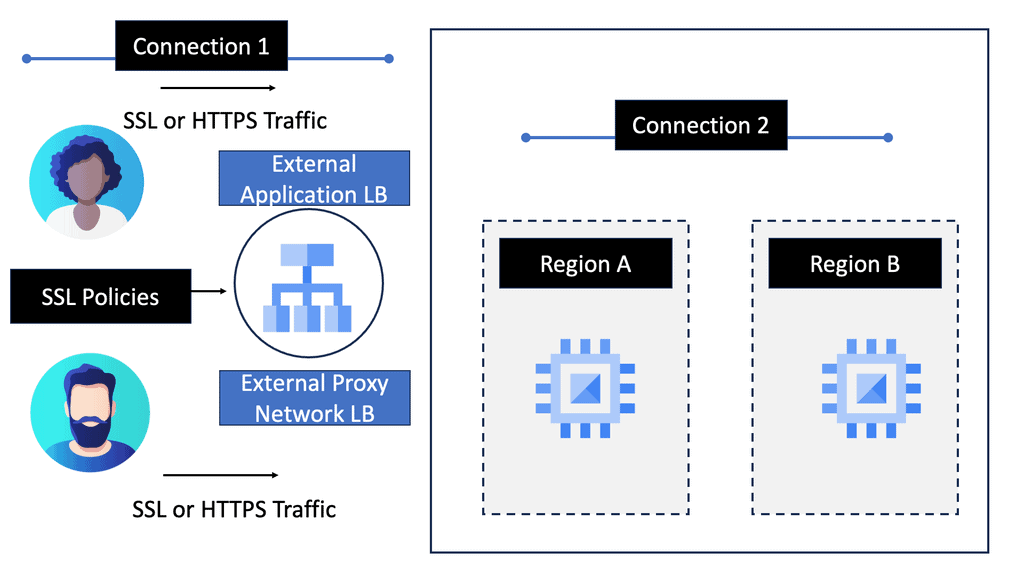
Google Cloud Load Balancing
**Types of Load Balancers Offered by Google Cloud**
Google Cloud provides several types of load balancers, each suited for different needs:
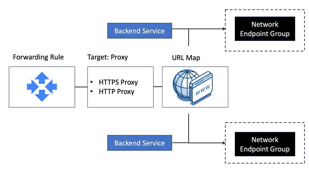
– **HTTP(S) Load Balancing:** Ideal for web applications, this distributes traffic based on HTTP and HTTPS protocols. It supports modern web standards, including HTTP/2 and WebSockets.
– **TCP/SSL Proxy Load Balancing:** This is perfect for non-HTTP traffic, providing global load balancing for TCP and SSL traffic, ensuring that applications remain responsive and available.
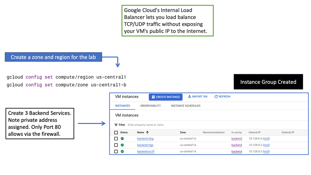
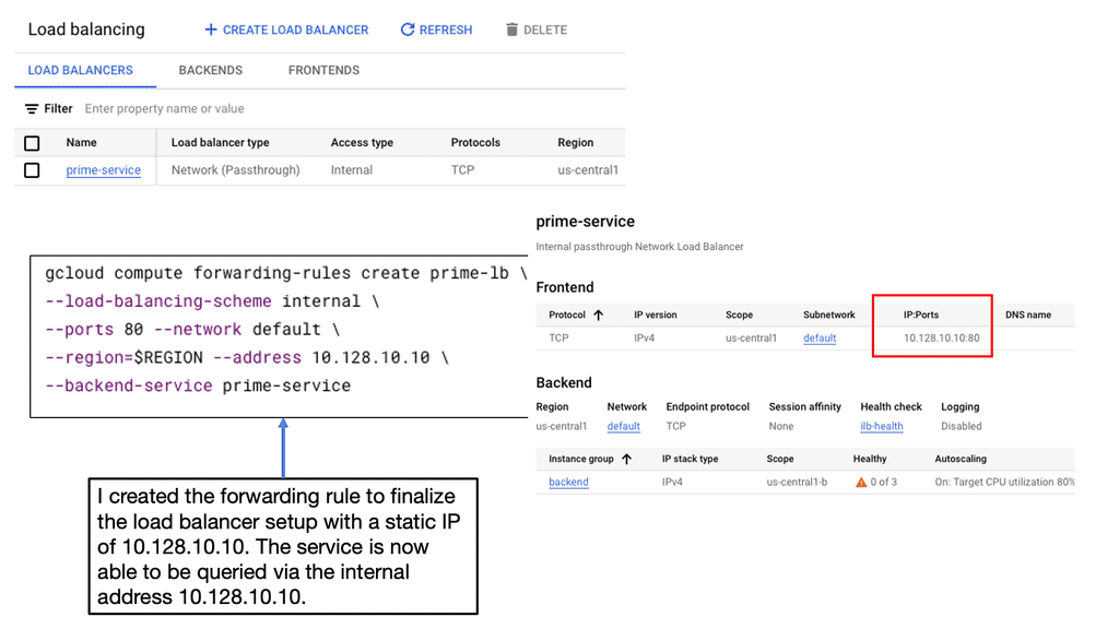
– **Internal Load Balancing:** Designed for internal applications that are not exposed to the internet, this helps manage traffic within your VPC network.
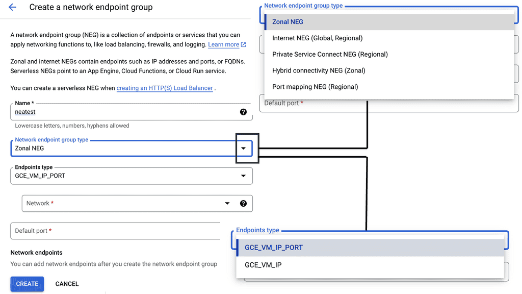
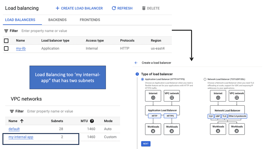
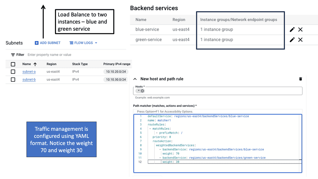
**Implementing Load Balancing with Google Cloud**
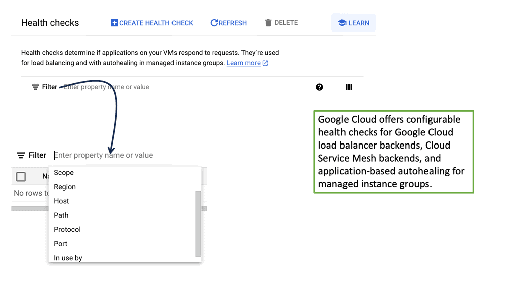
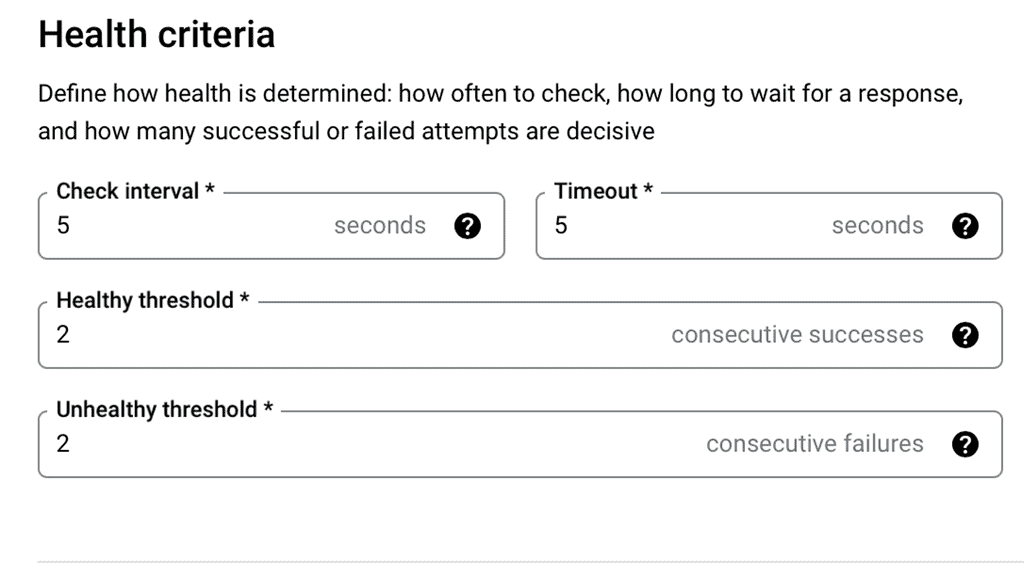
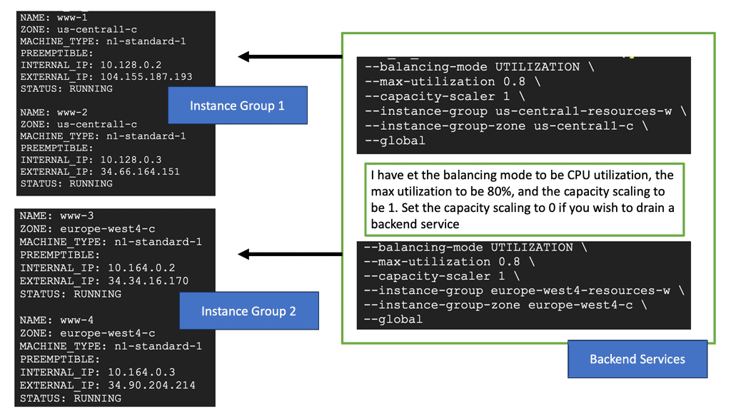
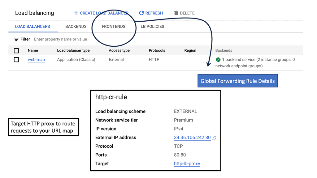
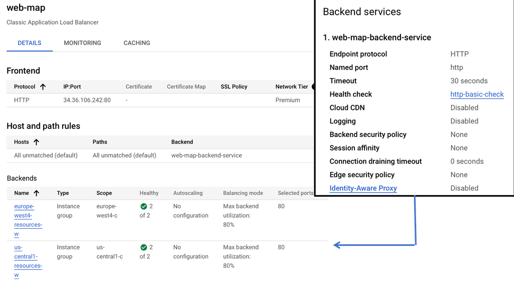
Setting up load balancing on Google Cloud is straightforward, thanks to its intuitive interface and comprehensive documentation. Start by identifying the type of load balancer that suits your application needs. Once chosen, configure the backend services, health checks, and routing rules to ensure optimal performance. Google Cloud also offers a range of tutorials and best practices to guide you through the process, ensuring that you can implement load balancing with ease and confidence.
**Strategies for Achieving Network Scalability**
Optimal layer three forwarding allows networks to scale seamlessly, accommodating growing traffic demands while maintaining high performance. Scalable networks offer numerous benefits to businesses and organizations. Firstly, they provide flexibility, allowing the network to adapt to changing requirements and accommodate growth without major disruptions. Scalable networks also enhance performance by distributing the workload efficiently, preventing congestion and ensuring smooth operations. Additionally, scalability promotes cost-efficiency by minimizing the need for frequent infrastructure upgrades and reducing downtime.
-Scalable Network Architecture: Designing a scalable network architecture is the foundation for achieving network scalability. This involves utilizing modular components, implementing redundant systems, and employing technologies like virtualization and cloud computing.
-Bandwidth Management: Effective bandwidth management is crucial for network scalability. It involves monitoring and optimizing bandwidth usage, prioritizing critical applications, and implementing Quality of Service (QoS) mechanisms to ensure smooth data flow.
-Scalable Network Equipment: Investing in scalable network equipment is essential for long-term growth. This includes switches, routers, and access points that can handle increasing traffic and provide room for expansion.
-Load Balancing: Implementing load balancing mechanisms helps distribute network traffic evenly across multiple servers or resources. This prevents overloading of specific devices and enhances overall network performance and reliability.
**Challenges and Solutions in Layer 3 Forwarding**
Despite its importance, Layer 3 forwarding can present several challenges:
– **Scalability Issues:** As networks grow, routing tables can become oversized, slowing down the forwarding process. Solutions like route summarization and hierarchical network design can mitigate this.
– **Security Concerns:** Ensuring secure data transmission is paramount. Implementing robust security protocols like IPsec can protect against threats while maintaining efficient routing.
– **Latency and Jitter:** High latency can disrupt real-time communication. Prioritizing traffic through Quality of Service (QoS) settings helps manage these issues effectively.
**Benefits of Optimal Layer 3 Forwarding**
1. Enhanced Scalability: Optimal Layer 3 forwarding allows networks to scale effectively by efficiently handling a growing number of connected devices and increasing traffic volumes. It enables seamless expansion without compromising network performance.
2. Improved Network Resilience: Optimized Layer 3 forwarding enhances network resilience by selecting the most efficient path for data packets. It enables networks to quickly adapt to network topology or link failure changes, rerouting traffic to ensure uninterrupted connectivity.
3. Better Resource Utilization: Optimal Layer 3 forwarding optimizes resource utilization by distributing traffic across multiple links. This enables efficient utilization of available network capacity, reducing the risk of bottlenecks and maximizing the network’s throughput.
4. Enhanced Security: Optimal Layer 3 forwarding contributes to network security by ensuring traffic is directed through secure paths. It also enables the implementation of firewall policies and access control lists, protecting the network from unauthorized access and potential security threats.
Implementing Optimal Layer 3 Forwarding:
To achieve optimal Layer 3 forwarding, various technologies and protocols are utilized, such as:
1. Routing Protocols: Dynamic routing protocols, such as OSPF (Open Shortest Path First) and BGP (Border Gateway Protocol), enable networks to exchange routing information automatically and determine the best path for data packets.
Achieving optimal layer 3 forwarding requires a comprehensive understanding of routing metrics, which are parameters used by routing protocols to determine the best path. Factors such as hop count, bandwidth, delay, and reliability play a significant role in this decision-making process.
By evaluating these metrics, routing protocols can select the most efficient path, reducing latency and improving overall network performance. Additionally, implementing quality of service (QoS) techniques can further enhance forwarding efficiency by prioritizing critical data packets.
2. Quality of Service (QoS): QoS mechanisms prioritize network traffic, ensuring that critical applications receive the necessary bandwidth and reducing the impact of congestion.
To achieve optimal layer 3 forwarding, various QoS mechanisms are employed. Traffic classification and marking are the first steps, where packets are analyzed and assigned a priority level based on their type and importance. This is followed by queuing and scheduling, where packets are managed and forwarded according to their priority.
Additionally, congestion management techniques like Weighted Fair Queuing (WFQ) can be leveraged to ensure that all traffic types receive fair treatment while prioritizing critical applications.
3. Network Monitoring and Analysis: Continuous network monitoring and analysis tools provide real-time visibility into network performance, enabling administrators to promptly identify and resolve potential issues.
While monitoring is about real-time observation, network analysis digs deeper into the data gathered to understand network behavior, troubleshoot issues, and plan for future upgrades. Analysis helps in identifying traffic patterns, understanding bandwidth usage, and detecting anomalies that could indicate security threats. By leveraging data analytics, businesses can optimize their network configurations, enhance security protocols, and ensure that their networks are robust and resilient.
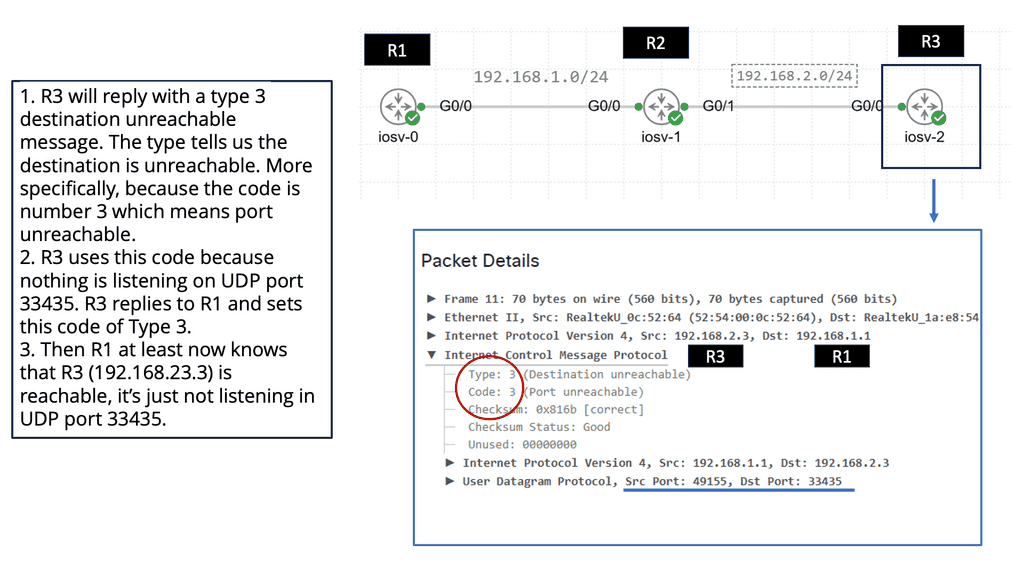
Traceroute – Testing Layer 3 Forwarding
**What is Traceroute?**
Traceroute is a network diagnostic tool used to track the path that data packets take from a source to a destination across an IP network. By sending out packets and recording the time it takes for each hop to respond, Traceroute provides a map of the network’s route. This tool is built into most operating systems, including Windows, macOS, and Linux, making it readily accessible for users.
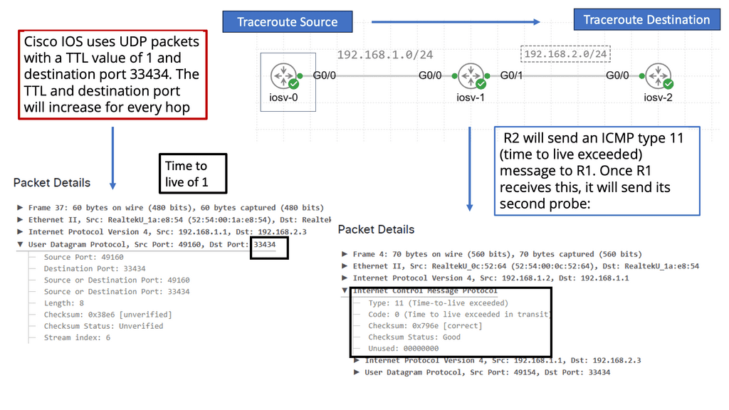
**How Does Traceroute Work?**
The operation of Traceroute relies on the Internet Control Message Protocol (ICMP) and utilizes Time-to-Live (TTL) values. When a packet is sent, its TTL value is decremented at each hop. Once the TTL reaches zero, the packet is discarded, and an ICMP “Time Exceeded” message is sent back to the sender. Traceroute increases the TTL value incrementally to discover each hop along the route, providing detailed information about each network segment.
**Why Use Traceroute?**
Traceroute is an essential tool for troubleshooting network issues. It helps identify where data packets are being delayed or dropped, making it easier to pinpoint network bottlenecks or outages. Additionally, Traceroute can reveal the geographical path of data, offering insights into the efficiency of the route and potential rerouting needs. Network engineers can use this information to optimize network performance and ensure data travels through the most efficient path.
Use Case: Understanding Performance-Based Routing
Performance-based routing is a dynamic routing technique that uses real-time data and metrics to determine the most efficient path for data packets to travel across a network; unlike traditional static routing, which relies on pre-defined paths, performance-based routing leverages intelligent algorithms and analytics to dynamically choose the optimal route based on bandwidth availability, latency, and network congestion.
By embracing performance-based routing, organizations can unlock a myriad of benefits. Firstly, it improves network efficiency by automatically rerouting traffic away from congested or underperforming links, ensuring an uninterrupted data flow. Secondly, it enhances user experience by minimizing latency and maximizing bandwidth utilization, leading to faster response times and smoother data transfers. Lastly, it optimizes cost by leveraging different network paths intelligently, reducing reliance on expensive dedicated links.
Implementing performance-based routing requires hardware, software, and network infrastructure. Organizations can choose from various solutions, including software-defined networking (SDN) controllers, intelligent routers, and network monitoring tools. These tools enable real-time monitoring and analysis of network performance metrics, allowing administrators to make data-driven routing decisions.
Optimal Layer 3 Forwarding – What is Routing?
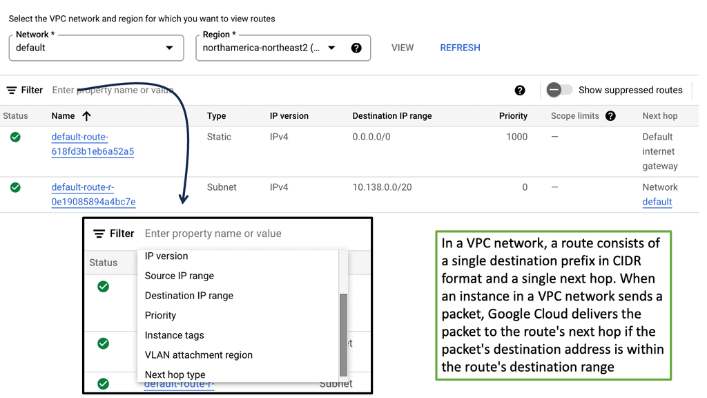
Routing is like a network’s GPS. It involves directing data packets from their source to their destination across multiple networks. Think of it as the process of determining the best possible path for data to travel. Routers, the essential devices responsible for routing, use various algorithms and protocols to make intelligent decisions about where to send data packets next.
Routing involves determining the most appropriate path for data packets to reach their destination. The next hop refers to the immediate network device to which a packet should be forwarded before reaching its final destination.
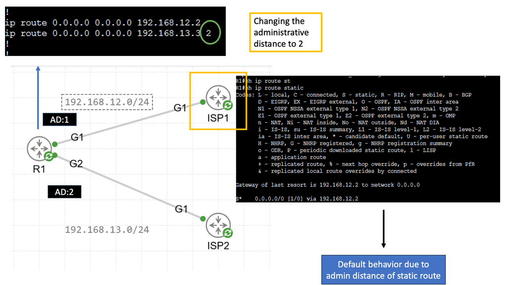
Administrative Distance
Administrative distance can be defined as a measure of the trustworthiness of a particular routing information source. It is a numerical value assigned to different routing protocols, indicating their level of reliability or preference. Essentially, administrative distance represents the “distance” between a router and the source of routing information, with lower values indicating higher reliability and trustworthiness.
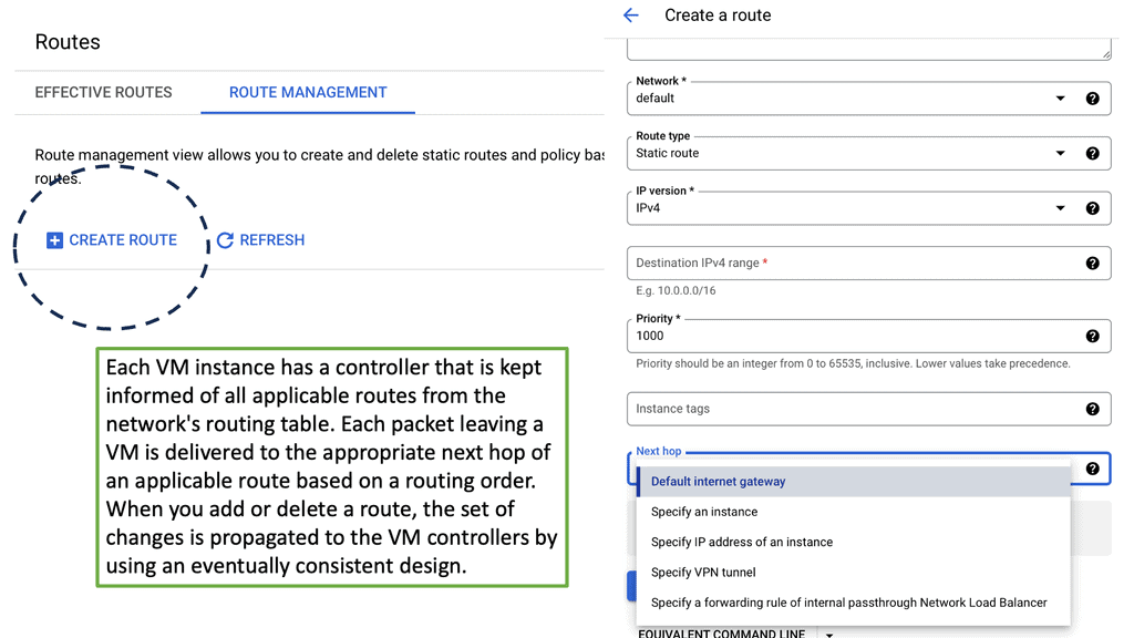
Static Routing
Static routing forms the backbone of network infrastructure, providing a manual route configuration. Unlike dynamic routing protocols, which adapt to network changes automatically, static routing relies on predetermined paths. Network administrators have complete control over traffic paths by manually configuring routes in the routing table.

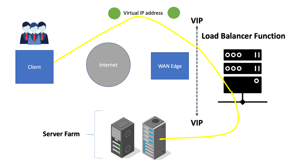
Load Balancing and Next Hop
In scenarios where multiple paths are available to reach a destination, load-balancing techniques come into play. Load balancing distributes the traffic across different paths, preventing congestion and maximizing network utilization. However, determining the optimal next hop becomes a challenge in load-balancing scenarios. We will explore the intricacies of load balancing and its impact on next-hop decisions.
Different load-balancing strategies exist, each with its approach to selecting the next hop. Dynamic load balancing algorithms adaptively choose the next hop based on real-time metrics like response time and server load, such as Least Response Time (LRT) and Weighted Least Loaded (WLL). On the other hand, static load balancing algorithms, like Round Robin and Static Weighted, distribute traffic evenly without considering dynamic factors.
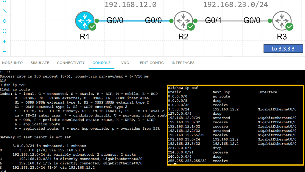
Understanding Cisco CEF
Cisco CEF is a high-performance, scalable packet-switching technology that operates at Layer 3 of the OSI model. Unlike traditional routing protocols, CEF utilizes a Forwarding Information Base (FIB) and an Adjacency Table (ADJ) to expedite the forwarding process. By maintaining a precomputed forwarding table, CEF minimizes the need for route lookups, resulting in superior performance.
Dynamic Routing Protocols and Next Hop Selection
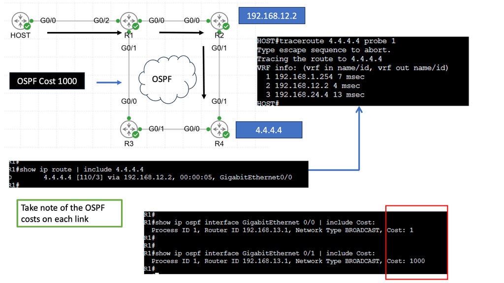
Dynamic routing protocols, such as OSPF (Open Shortest Path First) and BGP (Border Gateway Protocol), play a vital role in modern networks. These protocols dynamically exchange routing information among network devices, enabling efficient adaptation to network changes. Next-hop selection in dynamic routing protocols involves considering factors like path cost, network congestion, and link reliability. This section will provide insights into how dynamic routing protocols influence next-hop decisions.
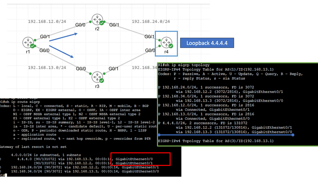
EIGRP (Enhanced Interior Gateway Routing Protocol) is a dynamic routing protocol widely used in enterprise networks. Load balancing with EIGRP involves distributing traffic across multiple paths to prevent congestion and ensure optimal utilization of available links. By intelligently spreading the load, EIGRP load balancing enhances network performance and enables efficient utilization of network resources.
Policy-Based Routing and Next Hop Manipulation
Policy-based routing allows network administrators to customize routing decisions based on specific criteria. It provides granular control over next-hop selection, enabling the implementation of complex routing policies.
Understanding Policy-Based Routing
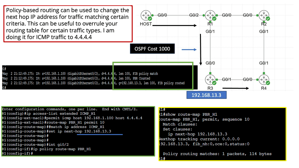
Policy-based routing is a technique that enables network administrators to make routing decisions based on policies defined at a higher level than traditional routing protocols. Unlike conventional routing, which relies on destination address alone, PBR considers additional factors such as source address, application type, and Quality of Service (QoS) requirements. Administrators gain fine-grained control over traffic flow, allowing for optimized network performance and enhanced security.
Implementation of Policy-Based Routing
Network administrators need to follow a few key steps to implement policy-based routing. Firstly, they must define the routing policies based on their specific requirements and objectives. This involves determining the matching criteria, such as source/destination address, application type, or protocol.
Once the policies are defined, they must be configured on the network devices, typically using command-line interfaces or graphical user interfaces provided by the network equipment vendors.
Additionally, administrators should monitor and fine-tune the PBR implementation to ensure optimal performance and adapt to changing network conditions.
Real-World Use Cases of Policy-Based Routing
Policy-based routing finds application in various scenarios across different industries. One everyday use case is in multi-homed networks, where traffic needs to be distributed across multiple internet service providers (ISPs) based on defined policies. PBR can also prioritize traffic for specific applications or users, ensuring critical services have the capacity and low latency. Moreover, policy-based routing enables network segmentation, allowing different departments or user groups to be isolated and treated differently based on their unique requirements.
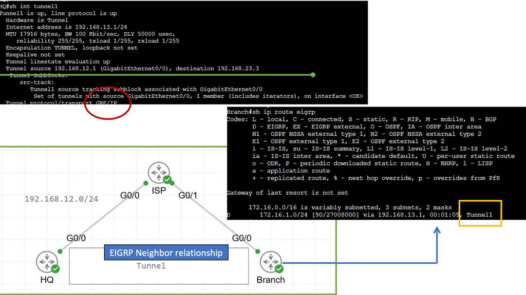
GRE and Next Hops
Generic Routing Encapsulation (GRE) is a tunneling protocol that enables the encapsulation of various network protocols within IP packets. It provides a flexible and scalable solution for deploying virtual private networks (VPNs) and connecting disparate networks over an existing IP infrastructure. By encapsulating multiple protocol types, GRE allows for seamless network communication, regardless of their underlying technologies. Notice the next hop below is the tunnel interface.
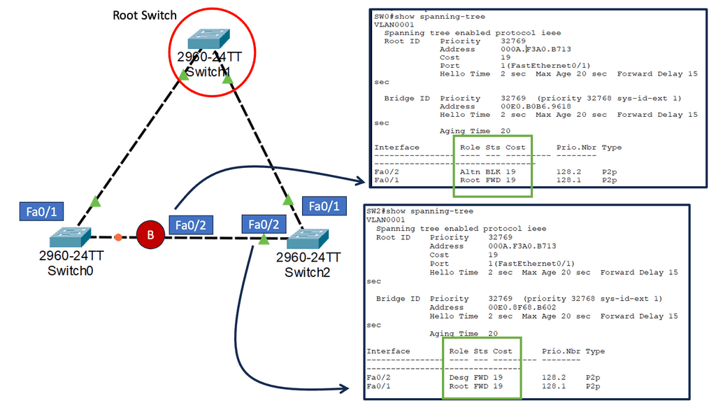
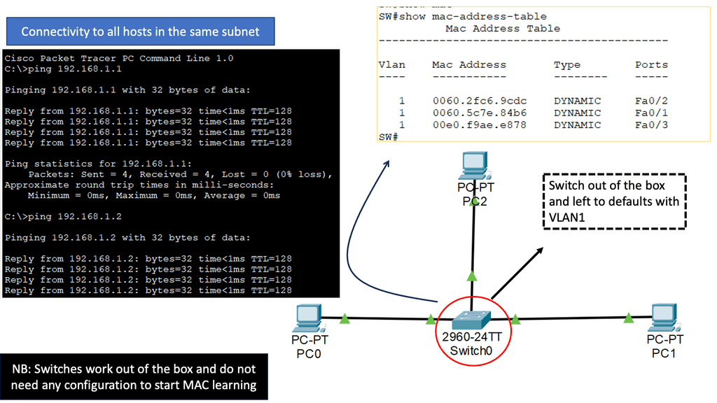
Recap: The Role of Switching
While routing deals with data flow between networks, switching comes into play within a single network. Switches serve as the traffic managers within a local area network (LAN). They connect devices, such as computers, printers, and servers, allowing them to communicate with one another. Switches receive incoming data packets and use MAC addresses to determine which device the data should be forwarded to. This efficient and direct communication within a network makes switching so critical.
VLAN performance challenges can arise from various factors. One common issue is VLAN congestion, which occurs when multiple VLANs compete for limited network resources. This congestion can increase latency, packet loss, and degraded network performance. Additionally, VLAN misconfigurations, such as improper VLAN tagging or overlapping IP address ranges, can also impact performance.
Recap: The Role of Segmentation
Segmentation is dividing a network into smaller, isolated segments or subnets. Each subnet operates independently, with its own set of rules and configurations. This division allows for better control and management of network traffic, leading to improved performance and security.
VLANs operate at the OSI model’s data link layer (Layer 2). They use switch technology to create separate broadcast domains within a network, enabling traffic isolation and control. VLANs can be configured based on department, function, or security requirements.
Achieving Optimal Layer 3 Forwarding:
Optimal Layer 3 forwarding ensures that data packets are transmitted through the most efficient path, improving network performance. It minimizes packet loss, latency, and jitter, enhancing user experience. By selecting the best path, optimal Layer 3 forwarding also enables load balancing, distributing the traffic evenly across multiple links, thus preventing congestion.
One key challenge in network performance is identifying and resolving bottlenecks. These bottlenecks can occur due to congested network links, outdated hardware, or inefficient routing protocols. Organizations can optimize bandwidth utilization by conducting thorough network assessments and employing intelligent traffic management techniques, ensuring smooth data flow and reduced latency.
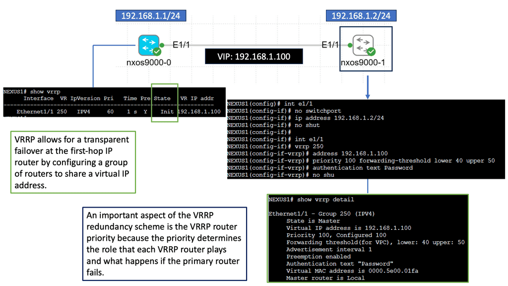
Understanding Nexus 9000 Series VRRP
Nexus 9000 Series VRRP is a protocol designed to provide router redundancy in a network environment, ensuring minimal downtime and seamless failover. It works by creating a virtual router using multiple physical routers, enabling seamless traffic redirection in the event of a failure. This protocol offers an active-passive architecture, where one router assumes the role of the primary router while others act as backups.
One key advantage of Nexus 9000 Series VRRP is its ability to provide network redundancy without the need for complex configurations. By leveraging VRRP, network administrators can ensure that their infrastructure remains operational despite hardware failures or network outages. Additionally, VRRP enables load balancing, allowing for efficient utilization of network resources.
Understanding Layer 3 Etherchannel
Layer 3 Etherchannel, also known as Multilayer Etherchannel or Port Aggregation Protocol (PAgP), is a technology that enables the bundling of multiple physical links between switches or routers into a single logical interface. Unlike Layer 2 Etherchannel, which operates at the data link layer, Layer 3 Etherchannel operates at the network layer, allowing for the distribution of traffic across parallel links based on IP routing protocols.
Layer 3 Etherchannel offers several advantages for network administrators and organizations. Firstly, it enhances network performance by increasing available bandwidth and enabling load balancing across multiple links. This results in improved data transmission speeds and reduced congestion. Additionally, Layer 3 Etherchannel provides redundancy, ensuring uninterrupted connectivity even during link failures. Distributing traffic across multiple links enhances network resiliency and minimizes downtime.

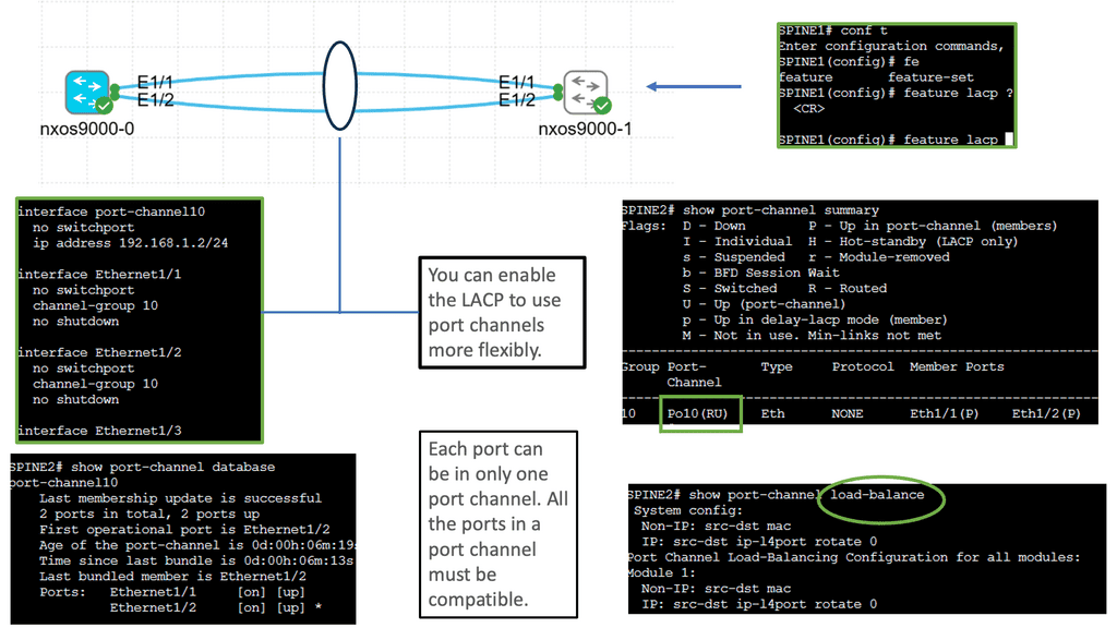
Benefits of Port Channel
a. Increased Bandwidth: With Port Channel, you can combine the bandwidth of multiple interfaces, significantly boosting your network’s overall capacity. This is especially crucial for bandwidth-intensive applications and data-intensive workloads.
b. Redundancy and High Availability: Port Channel offers built-in redundancy by distributing traffic across multiple interfaces. In a link failure, traffic seamlessly switches to the remaining active links, ensuring uninterrupted connectivity and minimizing downtime.
c. Load Balancing: The Port Channel technology intelligently distributes traffic across the bundled interfaces, optimizing the utilization of available resources. This results in better performance, reduced congestion, and enhanced user experience.
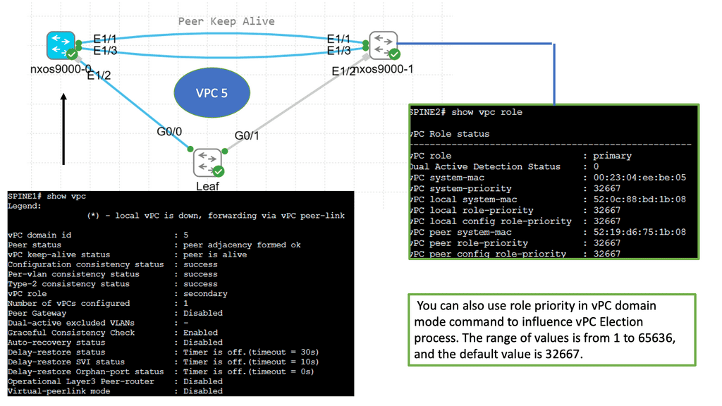
Understanding Cisco Nexus 9000 VPC
Cisco Nexus 9000 VPC is a technology that enables the creation of a virtual link aggregation group (LAG) between two Nexus switches. Combining multiple physical links into a single logical link increases bandwidth, redundancy, and load-balancing capabilities. This innovative feature allows for enhanced network flexibility and scalability.
One of the prominent features of Cisco Nexus 9000 VPC is its ability to eliminate the need for spanning tree protocol (STP) by enabling Layer 2 multipathing. This results in improved link utilization and better network performance.
Additionally, VPC offers seamless workload mobility, allowing live virtual machines (VMs) migration across Nexus switches without disruption. The benefits of Cisco Nexus 9000 VPC extend to simplified management, reduced downtime, and enhanced network resiliency.

Implementing Optimal Layer 3 Forwarding
Choose the Right Routing Protocols
a) Choosing the Right Routing Protocol: An appropriate routing protocol, such as OSPF, EIGRP, and BGP, is crucial for implementing optimal layer three forwarding. Routing protocols are algorithms or protocols that dictate how data packets are forwarded from one network to another. They establish the best paths for data transmission, considering network congestion, distance, and reliability.
One key area of routing protocol enhancements lies in introducing advanced metrics and load-balancing techniques. Modern routing protocols can evaluate network conditions, latency, and link bandwidth by considering factors beyond traditional metrics like hop count. This enables intelligent load balancing, distributing traffic across multiple paths to prevent congestion and maximize network efficiency.
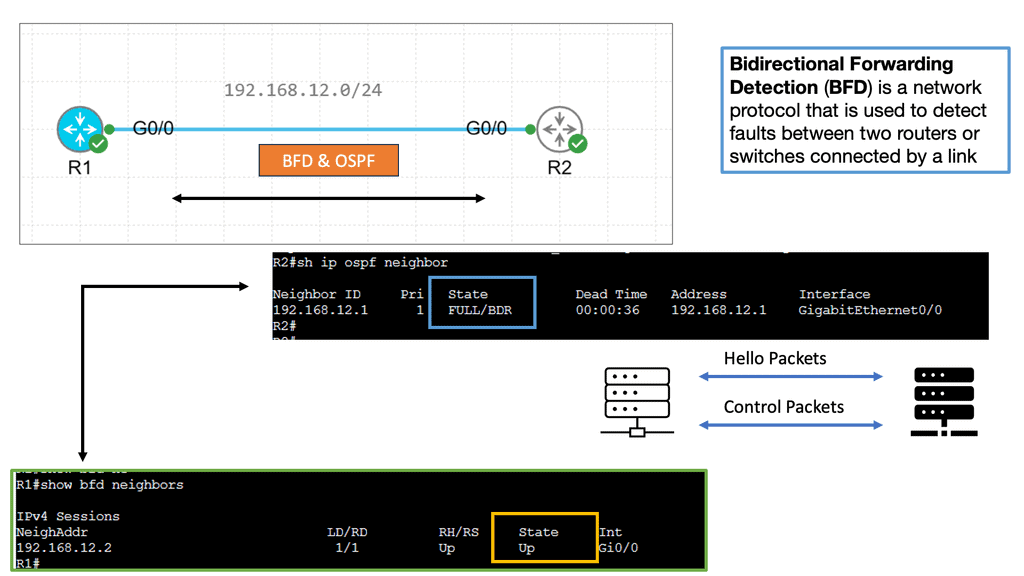
Example Technology: BFD
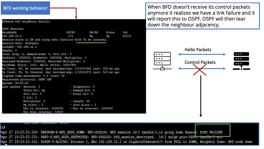
Bidirectional Forwarding Detection (BFD) is a lightweight protocol designed to detect link failures quickly. It operates at the network layer and detects rapid failure between adjacent routers or devices. BFD accomplishes this by sending periodic control packets, known as BFD control packets, to monitor the status of links and detect any failures.
BFD plays a vital role in achieving rapid routing protocol convergence. By providing fast link failure detection, BFD allows routing protocols to detect and respond to failures swiftly. When a link failure is detected by BFD, it triggers routing protocols to recalculate paths and update forwarding tables, minimizing the failure’s impact on network connectivity.
Enforce Network Segmentation
b) Network Segmentation: Breaking down large networks into smaller subnets enhances routing efficiency and reduces network complexity. By dividing the network into smaller segments, managing and controlling the data flow becomes easier. Each segment can have its security policies, access controls, and monitoring mechanisms. Segmentation improves network performance by reducing congestion and optimizing data flow. It allows organizations to prioritize critical traffic and allocate resources effectively.
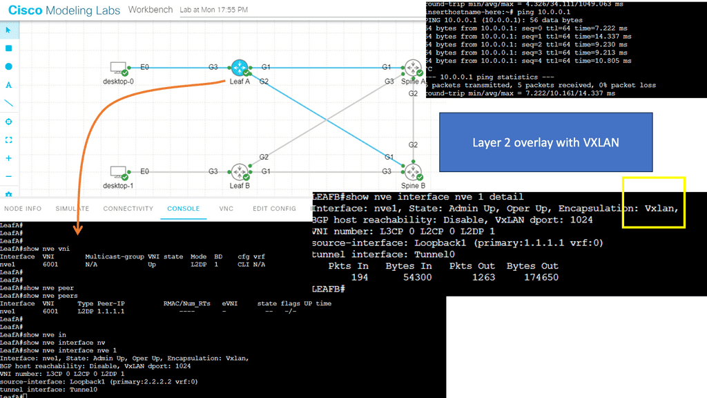
Example: Segmentation with VXLAN
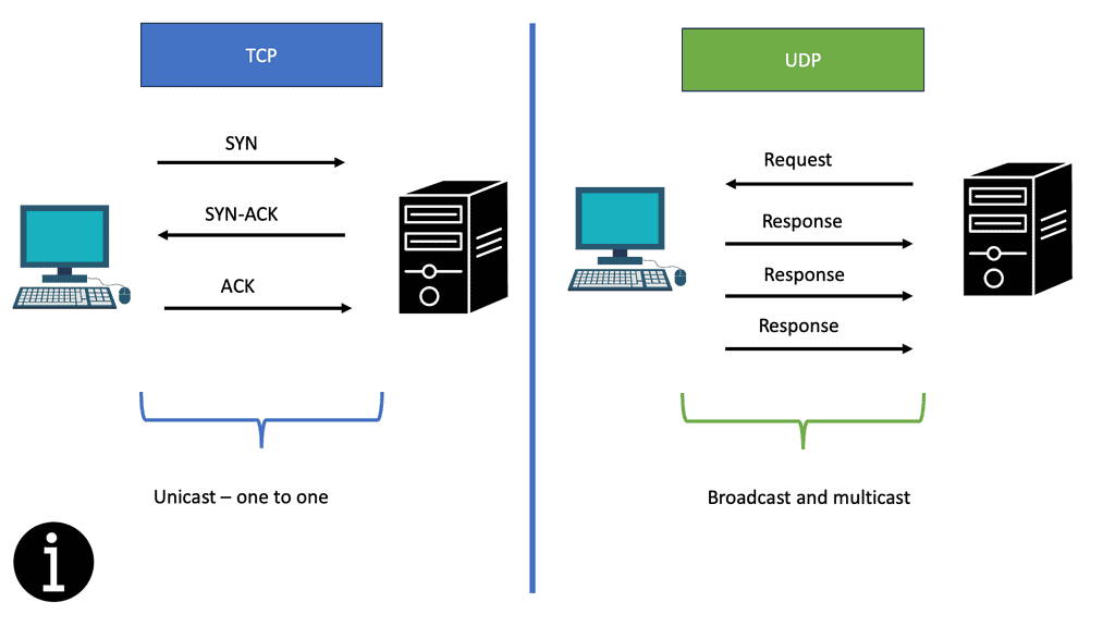
VXLAN is a groundbreaking technology that addresses the limitations of traditional VLANs. It provides a scalable solution for network segmentation by leveraging overlay networks. VXLAN encapsulates Layer 2 Ethernet frames in Layer 3 UDP packets, enabling the creation of virtual Layer 2 networks over an existing Layer 3 infrastructure. This allows for greater flexibility, improved scalability, and simplified network management.
Implement Traffic Engineering
c) Traffic Engineering: Network operators can further optimize layer three forwarding by leveraging traffic engineering techniques, such as MPLS or segment routing. Network traffic engineering involves the strategic management and control of network traffic flow. It encompasses various techniques and methodologies to optimize network utilization and enhance user experience. Directing traffic intelligently aims to minimize congestion, reduce latency, and improve overall network performance.
– Traffic Shaping: This technique regulates network traffic flow to prevent congestion and ensure a fair bandwidth distribution. By prioritizing certain types of traffic, such as real-time applications or critical data, traffic shaping can effectively optimize network resources.
– Load Balancing: Load balancing distributes network traffic across multiple paths or servers, evenly distributing the workload and preventing bottlenecks. This technique improves network performance, increases scalability, and enhances fault tolerance.
IPv6 Optimal Forwarding
Understanding Router Advertisement Preference
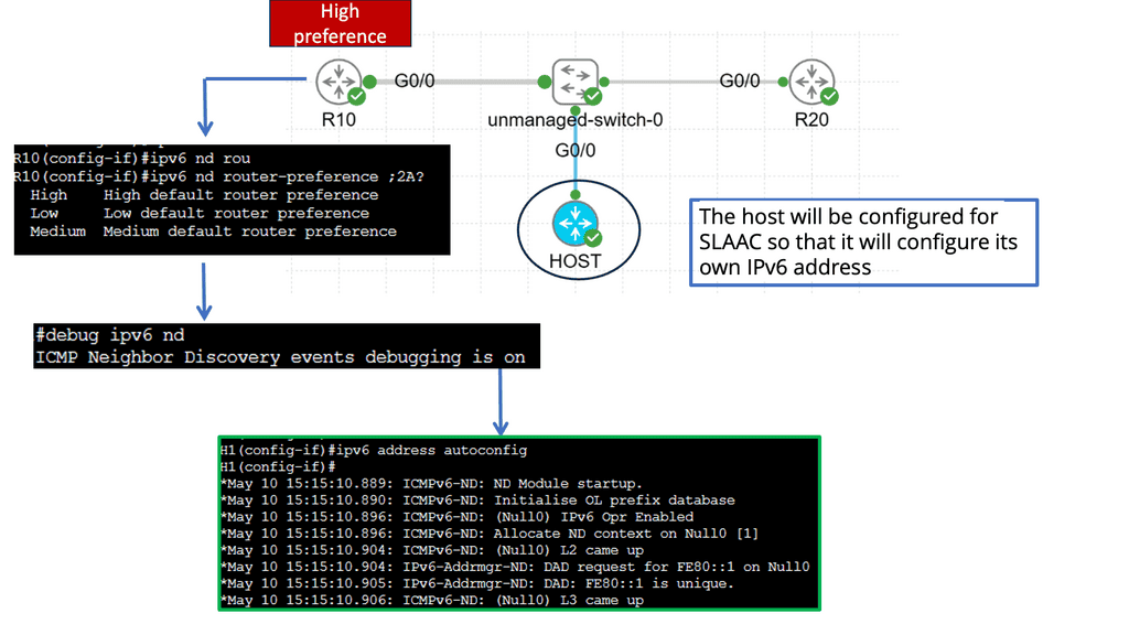
The first step in comprehending Router Advertisement Preference is to understand its purpose. RAs are messages routers send to announce their presence and provide crucial network configuration information. These messages contain various parameters, including the Router Advertisement Preference, which determines the priority of the routers in the network.
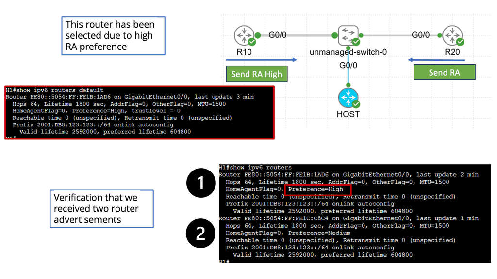
IPv6 Router Advertisement Preference offers three main options: High, Medium, and Low. Each of these preferences has a specific impact on how devices on the network make their choices. High-preference routers are prioritized over others, while Medium and low-preference routers are considered fallback options if the High-preference router becomes unavailable.
Several factors influence the Router Advertisement Preference selection process. These factors include the source of the RA, the router’s priority level, and the network’s trustworthiness. By carefully considering these factors, network administrators can optimize their configurations to ensure efficient routing and seamless connectivity.
Configuring Router Advertisement Preference involves various steps, depending on the network infrastructure and the devices involved. Some common methods include modifying router settings, using network management tools, or implementing specific protocols like DHCPv6 to influence the preference selection process. Understanding the network’s specific requirements is crucial for effective configuration.
Implementing Quality of Service (QoS) Policies
Implementing quality of service (QoS) policies is essential to prioritizing critical applications and ensuring optimal user experience. QoS allows network administrators to allocate network resources based on application requirements, guaranteeing a minimum level of service for high-priority applications. Organizations can prevent congestion, reduce latency, and deliver consistent performance by classifying and prioritizing traffic flows.
Leveraging Load Balancing Techniques
Load Balancing: Distributing traffic across multiple paths optimizes resource utilization and prevents bottlenecks.
Load balancing is crucial in distributing network traffic across multiple servers or links, optimizing resource utilization, and preventing overload. Organizations can achieve better network performance, fault tolerance, and enhanced scalability by implementing intelligent load-balancing algorithms. Load balancing techniques, such as round-robin, least connections, or weighted distribution, ensure efficient utilization of network resources.
Example: EIGRP configuration
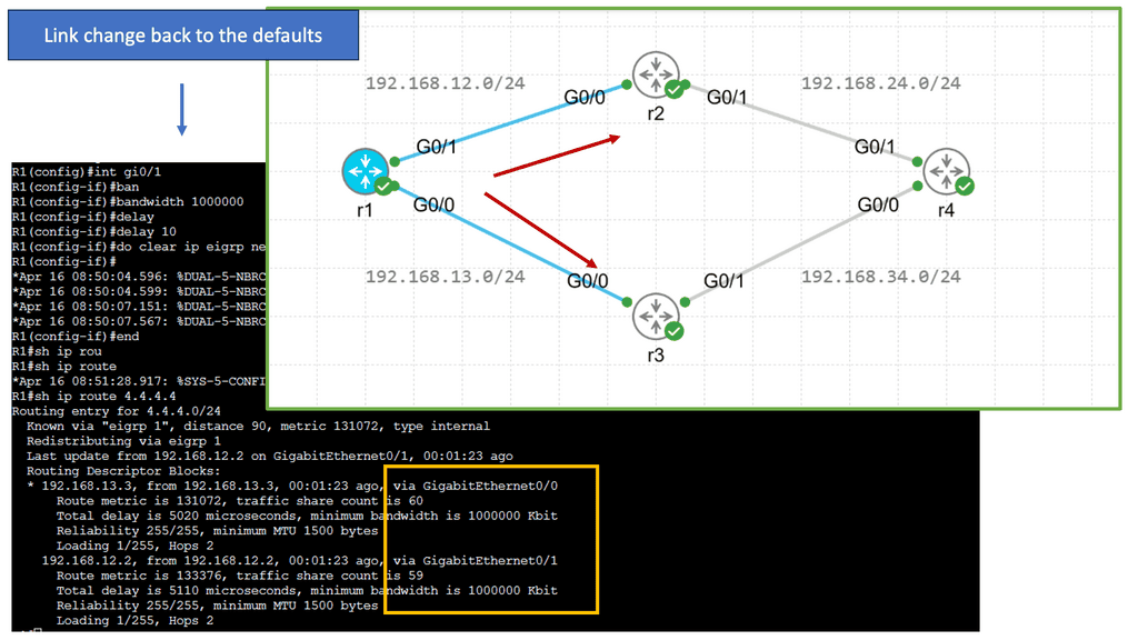
EIGRP is an advanced distance-vector routing protocol developed by Cisco Systems. It is known for its fast convergence, efficient bandwidth use, and support for IPv4 and IPv6 networks. Unlike traditional distance-vector protocols, EIGRP utilizes a more sophisticated Diffusing Update Algorithm (DUAL) to determine the best path to a destination. This enables networks to adapt quickly to changes and ensures optimal routing efficiency.
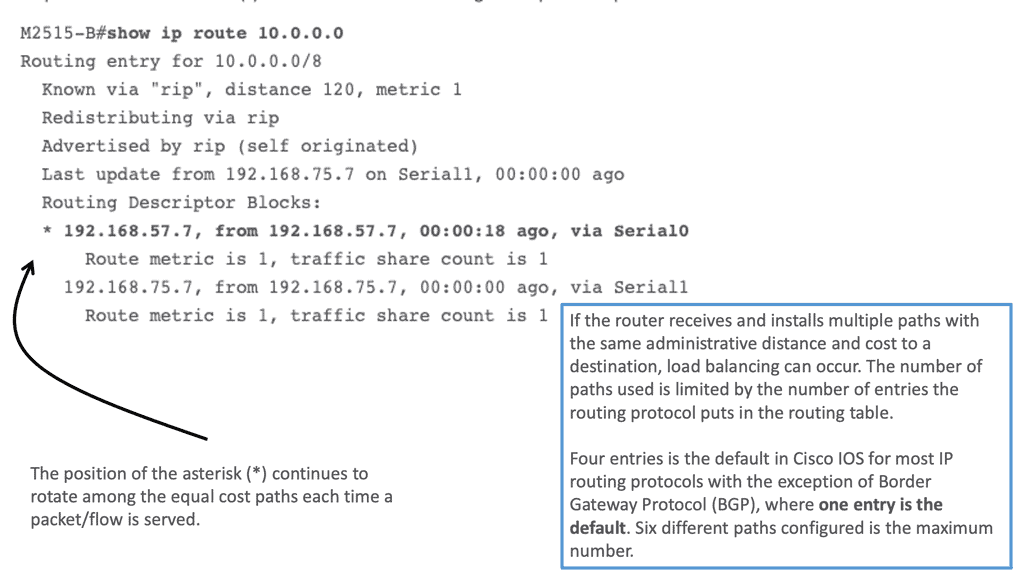
EIGRP load balancing enables routers to distribute traffic among multiple paths, maximizing the utilization of available resources. It is achieved through the equal-cost multipath (ECMP) mechanism, which allows for the simultaneous use of various routes with equal metrics. By leveraging ECMP, EIGRP load balancing enhances network reliability, minimizes congestion, and improves overall performance
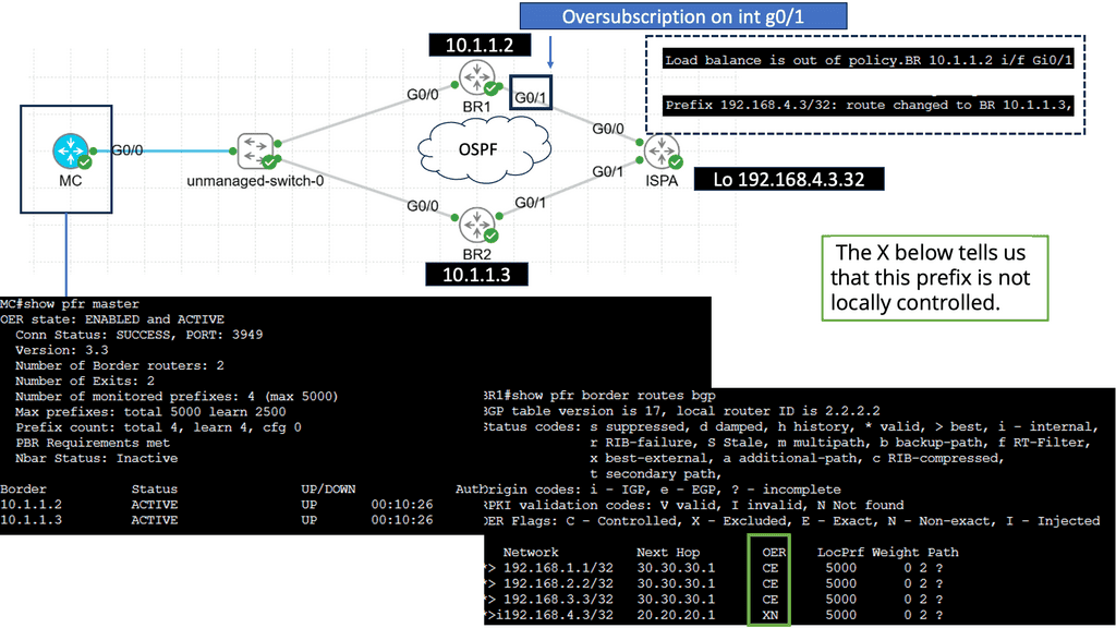
**Use Case: Performance Routing**
Understanding Performance Routing
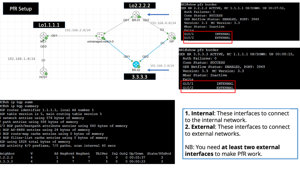
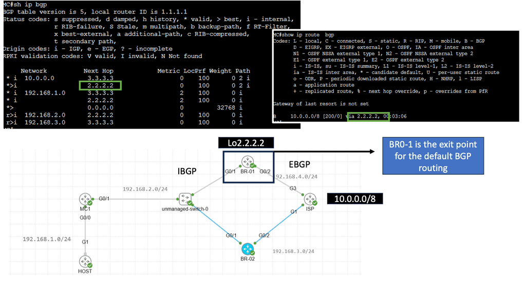
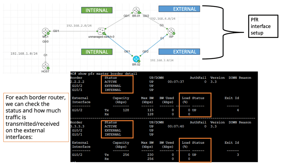
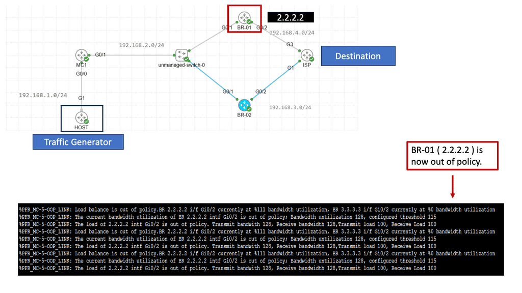
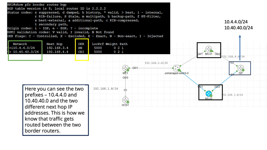
PfR, or Cisco Performance Routing, is an advanced network routing technology designed to optimize network traffic flow. Unlike traditional static routing, PfR dynamically selects the best path for traffic based on predefined policies and real-time network conditions. By monitoring network performance metrics such as latency, jitter, and packet loss, PfR intelligently routes traffic to ensure efficient utilization of network resources and improved user experience.
PfR operates through a three-step process: monitoring, decision-making, and optimization. In the monitoring phase, PfR continuously collects performance data from various network devices and probes, gathering information about network conditions such as delay, loss, and jitter.
Based on this data, PfR makes intelligent decisions in the decision-making phase, analyzing policies and constraints to select the optimal traffic path. Finally, in the optimization phase, PfR dynamically adjusts the traffic flow, rerouting packets based on the chosen path and continuously monitoring network performance to adapt to changing conditions.

**Advanced Topics**
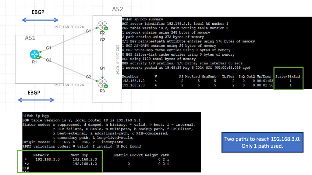
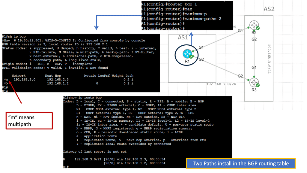
BGP Multipath
BGP Multipath refers to BGP’s ability to install multiple paths into the routing table for the same destination prefix. Traditionally, BGP only selects and installs a single best path based on factors like path length, AS path, etc. However, with Multipath, BGP can install and utilize multiple paths concurrently, enhancing flexibility and improved network performance.
The utilization of BGP Multipath brings several advantages to network operators. Firstly, it allows for load balancing across multiple paths, distributing traffic and preventing congestion on any single link. This load-balancing mechanism enhances network efficiency and ensures optimal resource utilization. Additionally, Multipath increases network resiliency by providing redundancy. In a link failure, traffic can be seamlessly rerouted through alternate paths, minimizing downtime and improving overall network reliability.
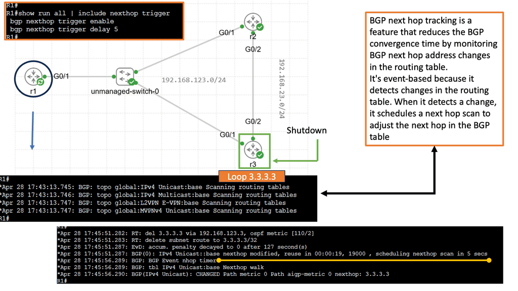
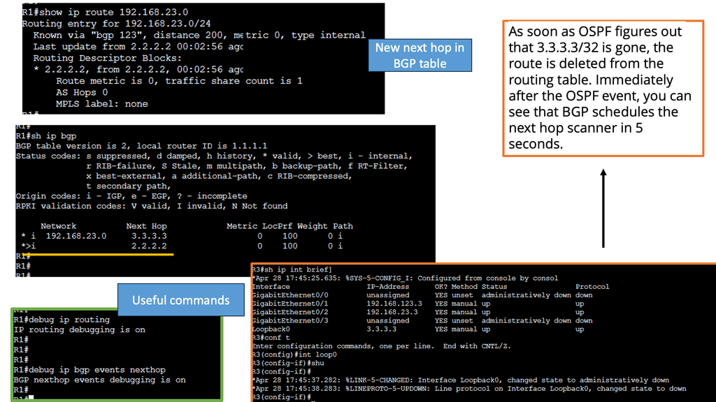
Example Feature: BGP Next Hop Tracking
BGP next-hop tracking is a mechanism used to validate the reachability of the next-hop IP address. It verifies that the next hop advertised by BGP is indeed reachable, preventing potential routing issues. By continuously monitoring the next hop status, network administrators can ensure optimal routing decisions and maintain network stability.
BGP next-hop tracking is a mechanism used to validate the reachability of the next-hop IP address. It verifies that the next hop advertised by BGP is indeed reachable, preventing potential routing issues. By continuously monitoring the next hop status, network administrators can ensure optimal routing decisions and maintain network stability.
The implementation of BGP next-hop tracking offers several key benefits. First, it enhances network resilience by detecting and reacting promptly to next-hop failures. This proactive approach prevents traffic black-holing and minimizes service disruptions. Additionally, it enables efficient load balancing by accurately identifying the available next-hop options based on their reachability status.
Understanding BGP Route Reflection
At its core, BGP route reflection is a technique used to alleviate the burden of full mesh configurations within BGP networks. Traditionally, each BGP router would establish a full mesh of connections with its peers, exponentially increasing the number of sessions as the network expands. However, with route reflection, certain routers are designated as route reflectors, simplifying the mesh and reducing the required sessions.
Route reflectors act as centralized points for reflection, collecting, and disseminating routing information to other routers in the network. They maintain a separate BGP table, the reflection table, which stores all the routing information received from clients and other route reflectors. By consolidating this information, route reflectors enable efficient propagation of updates, reducing the need for full-mesh connections.


Technologies Driving Enhanced Network Scalability
The Rise of Software-Defined Networking (SDN): Software-Defined Networking (SDN) has emerged as a game-changer in network scalability. By decoupling the control plane from the data plane, SDN enables centralized network management and programmability. This approach significantly enhances network flexibility, allowing organizations to dynamically adapt to changing traffic patterns and scale their networks with ease.
- Network Function Virtualization
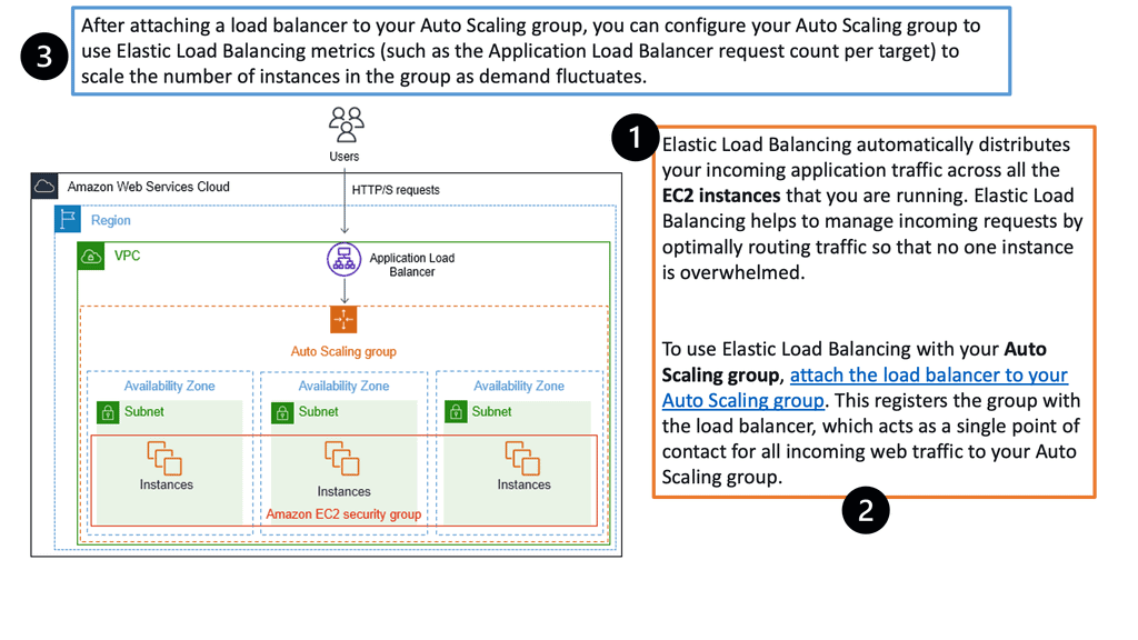
Network Function Virtualization (NFV): Network Function Virtualization (NFV) complements SDN by virtualizing network services that were traditionally implemented using dedicated hardware devices. By running network functions on standard servers or cloud infrastructure, NFV eliminates the need for physical equipment, reducing costs and improving scalability. NFV empowers organizations to rapidly deploy and scale network functions such as firewalls, load balancers, and intrusion detection systems, leading to enhanced network agility.
- Emergence of Edge Computing
The Emergence of Edge Computing: With the proliferation of Internet of Things (IoT) devices and real-time applications, the demand for low-latency and high-bandwidth connectivity has surged. Edge computing brings computational capabilities closer to the data source, enabling faster data processing and reduced network congestion. By leveraging edge computing technologies, organizations can achieve enhanced network scalability by offloading processing tasks from centralized data centers to edge devices.
- Artificial Intelligence & Machine Learning
The Power of Artificial Intelligence (AI) and Machine Learning (ML): AI and ML are revolutionizing network scalability by optimizing network performance, predicting traffic patterns, and automating network management. These technologies enable intelligent traffic routing, congestion control, and predictive scaling, ensuring that networks can dynamically adapt to changing demands. By harnessing the power of AI and ML, organizations can achieve unprecedented levels of network scalability and efficiency.
**Vendor Example: Arista with Large Layer-3 Multipath**
Network congestion: In complex network environments, layer 3 forwarding can lead to congestion if not correctly managed. Network administrators must carefully monitor and analyze traffic patterns to proactively address congestion issues and optimize routing decisions.
Arista EOS supports hardware for Leaf ( ToR ), Spine, and Spline data center design layers. Its wide product range supports significant layer-3 multipath ( 16 – 64-way ECMP ) with excellent optimal Layer 3-forwarding technologies. Unfortunately, multi-protocol Label Switching ( MPLS ) is limited to static MPLS labels, which could become an operational nightmare. Currently, no Fibre Channel over Ethernet ( FCoE ) support exists.
Arista supports massive Layer-2 Multipath with ( Multichassis Link aggregation ) MLAG. Validated designs with Arista Core 7508 switches ( offer 768 10GE ports ) and Arista Leaf 7050S-64 support over 1980 x 10GE server ports with 1:2,75 oversubscription. That’s a lot of 10GE ports. Do you think layer 2 domains should be designed to that scale?
Related: Before you proceed, you may find the following helpful:
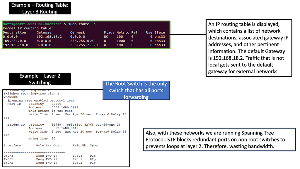
Every IP host in a network is configured with its IP address and mask and the IP address of the default gateway. Suppose the host wants to send traffic, which, in our case, is to a destination address that does not belong to a subnet to which the host is directly attached; the host passes the packet to the default gateway, which would be a Layer 3 router.
The Role of The Default Gateway
A standard misconception is how the address of the default gateway is used. People mistakenly believe that when a packet is sent to the Layer 3 default router, the sending host sets the destination address in the IP packet as the default gateway router address. However, if this were the case, the router would consider the packet addressed to itself and not forward it any further. So why configure the default gateway’s IP address?
First, the host uses the Address Resolution Protocol (ARP) to find the specified router’s Media Access Control (MAC) address. Then, having acquired the router’s MAC address, the host sends the packets directly to it as data link unicast submissions.

Google Cloud Data Centers
Understanding VPC Networking
VPC Networking, short for Virtual Private Cloud Networking, provides organizations with a customizable and private virtual network environment. It allows users to create and manage virtual machines, instances, and other resources within their own isolated network.

a) Subnets and IP Address Management: VPC Networking enables the subdivision of a network into multiple subnets, each with its own range of IP addresses, facilitating better organization and control.
b) Firewall Rules and Network Security: With VPC Networking, users can define and manage firewall rules to control network traffic, ensuring the highest level of security for their resources.
c) VPN and Direct Peering: VPC Networking offers secure connectivity options, such as VPN tunnels and direct peering, allowing users to establish reliable connections between their on-premises infrastructure and the cloud.


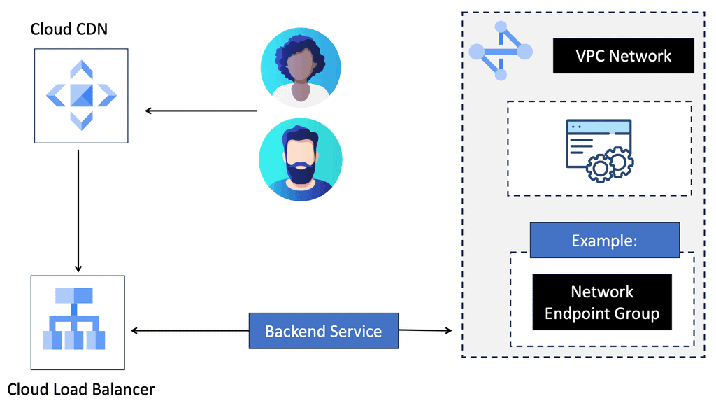
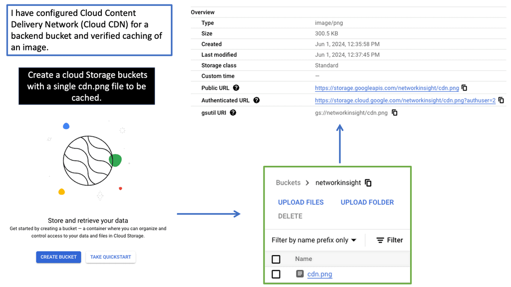
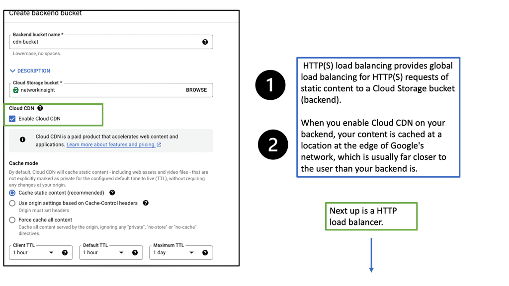
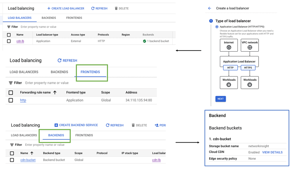
Understanding the Basics of Cloud CDN
Cloud CDN is a globally distributed network of servers strategically placed across various locations. This network acts as a middleman between users and content providers, ensuring faster content delivery by serving cached copies of web content from the server closest to the user’s location. By leveraging Google’s robust infrastructure, Cloud CDN minimizes latency, reduces bandwidth costs, and enhances the overall user experience.
Accelerated Content Delivery: Cloud CDN employs advanced caching techniques to store frequently accessed content at edge locations. This minimizes the round-trip time and enables near-instantaneous content delivery, regardless of the user’s location.
Global Scalability: With Cloud CDN, businesses can scale their content delivery operations globally. The network’s extensive presence across multiple regions ensures that content is delivered with optimal speed, regardless of the user’s geographical location.
Cost Efficiency: Cloud CDN significantly reduces bandwidth usage by serving cached content and mitigates the strain on origin servers. This leads to substantial cost savings by minimizing data transfer fees and lowering infrastructure requirements.
Arista deep buffers: Why are they important?
A vital switch table you need to be concerned with for large 3 networks is the size of Address Resolution Protocol ( ARP ) tables. When ARP tables become full and packets are offered with the destination ( next hop ) that isn’t cached, the network will experience flooding and suffer performance problems.
Arista Spine switches have deep buffers, which are ideal for bursty- and latency-sensitive environments. They are also perfect when you have little knowledge of the application traffic matrix, as they can handle most types efficiently.
Finally, deep buffers are most useful in spine layers, where traffic concentration occurs. If you are concerned that ToR switches do not have enough buffers, physically direct servers to chassis-based switches in the Core / Spine layer.
Vendor Solutions: Optimal layer 3 forwarding
Every data center has some mix of layer 2 bridging and layer 3 forwardings. The design selected depends on layer 2 / layer 3 boundaries. Data centers that use MAC-over-IP usually have layer 3 boundaries on the ToR switch. Fully virtualized data centers require large layer 2 domains ( for VM mobility ), while VLANs span Core or Spine layers.
Either of these designs can result in suboptimal traffic flow. Layer 2 forwarding in ToR switches and layer 3 forwarding in Core may result in servers in different VLANs connected to the same ToR switches being hairpinned to the closest Layer 3 switch.
Solutions that offer optimal Layer 3 forwarding in the data center were available. These may include stacking ToR switches, architectures that present the whole fabric as a single layer 3 elements ( Juniper QFabric ), and controller-based architectures (NEC’s Programmable Flow ). While these solutions may suffice for some business requirements, they don’t have optimal Layer 3 forward across the whole data center while using sets of independent devices.
Arista Virtual ARP does this. All ToR switches share the same IP and MAC with a common VLAN. Configuration involves the same first-hop gateway IP address on a VLAN for all ToR switches and mapping the MAC address to the configured shared IP address. The design ensures optimal Layer 3 forwarding between two ToR endpoints and optimal inbound traffic forwarding.

Load balancing enhancements
Arista 7150 is an ultra-low-latency 10GE switch ( 350 – 380 ns ). It offers load-balancing enhancements other than the standard 5-tuple mechanism. Arista supports new load-balancing profiles. Load-balancing profiles allow you to decide what bit and byte of the packet you want to use as the hash for the load-balancing mechanism, offering more scope and granularity than the traditional 5-tuple mechanism.
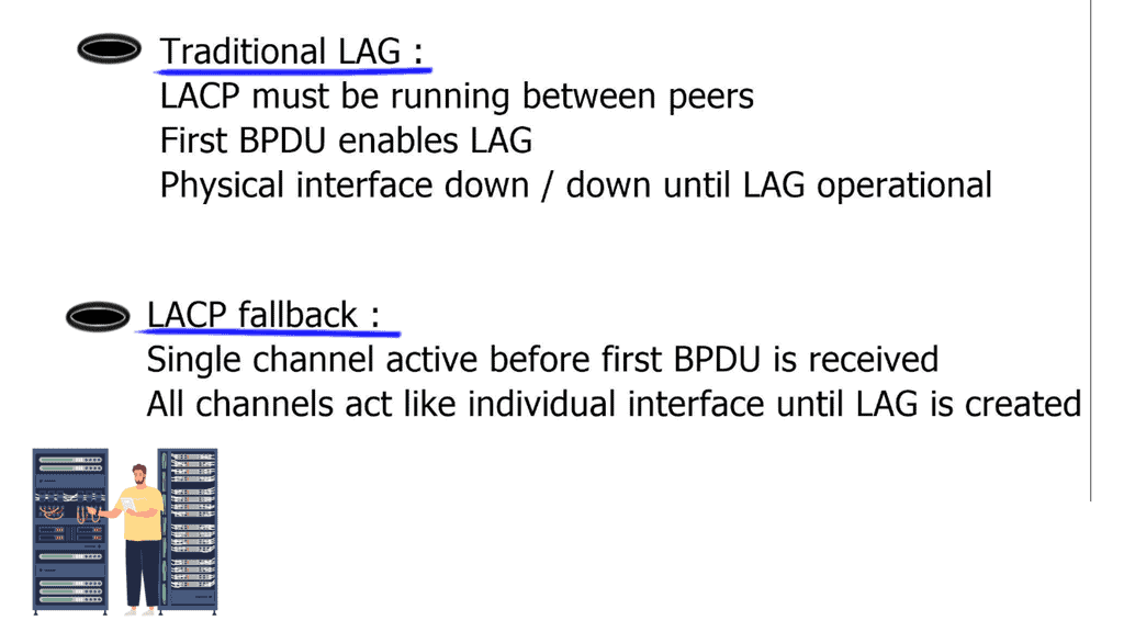
LACP fallback
With traditional Link Aggregation ( LAG ), LAG is enabled after receiving the first LACP packet. This is because the physical interfaces are not operational and are down / down before receiving LACP packets. This is viable and perfectly OK unless you need auto-provisioning. What does LACP fallback mean?
If you don’t receive an LACP packet and the LACP fallback is configured, one of the links will still become active and will be UP / UP. Continue using the Bridge Protocol Data Unit ( BPDU ) guard on those ports, as you don’t want a switch to bridge between two ports, create a forwarding loop.
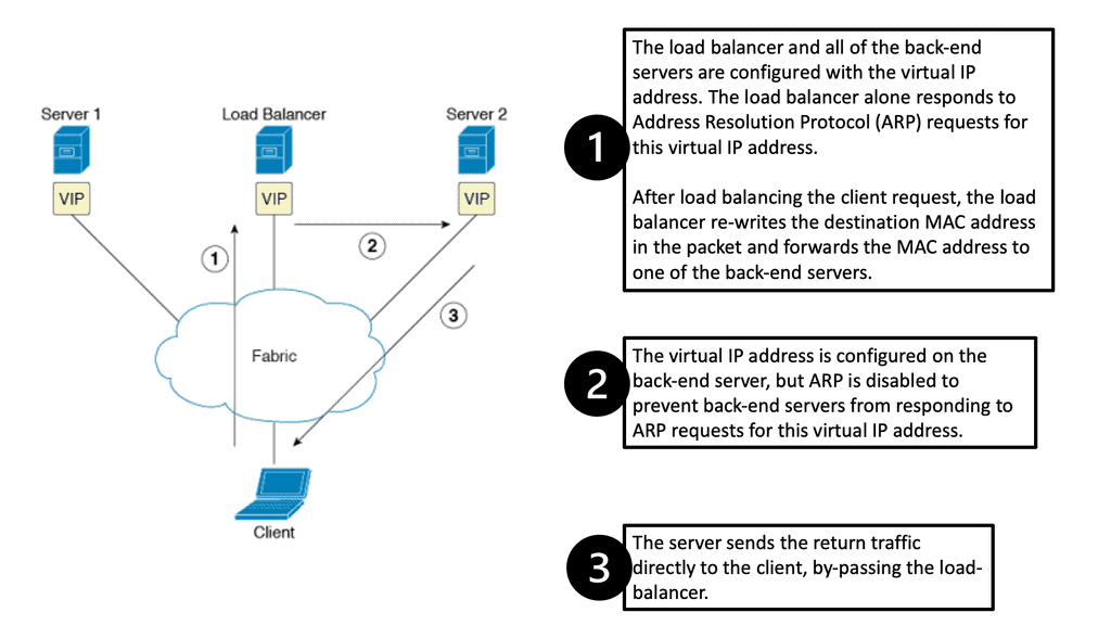
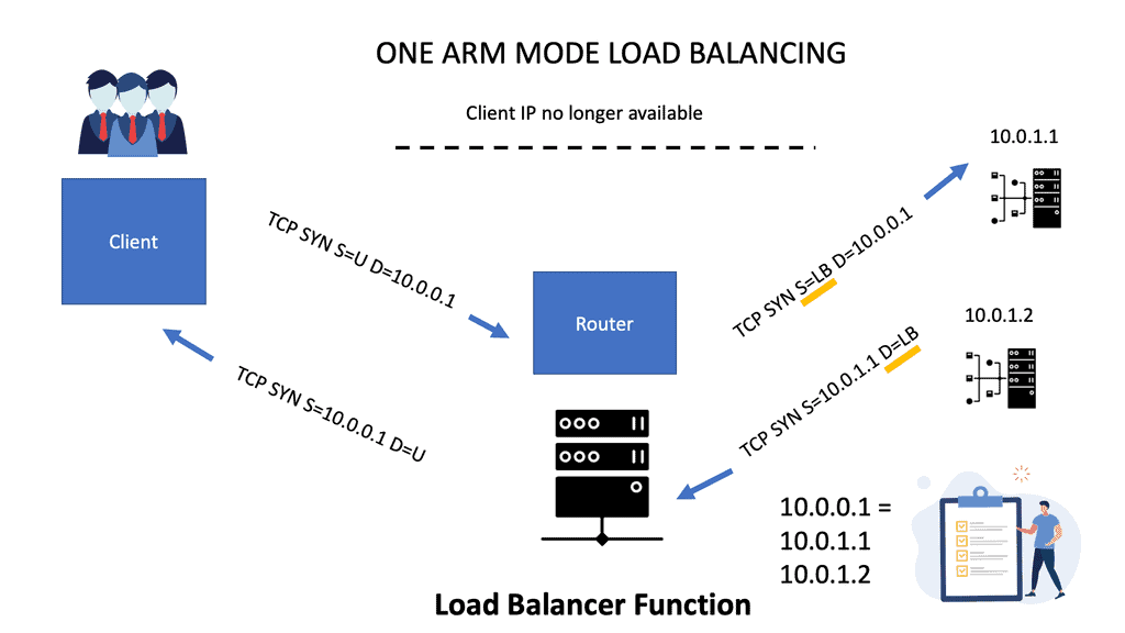
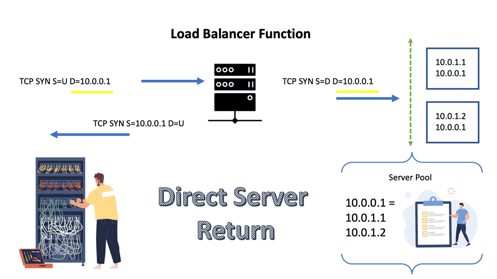
Direct server return
7050 series supports Direct Server Return. The load balancer in the forwarding path does not do NAT. Implementation includes configuring VIP on the load balancer’s outside IP and the internal servers’ loopback. It is essential not to configure the same IP address on server LAN interfaces, as ARP replies will clash. The load balancer sends the packet unmodified to the server, and the server sends it straight to the client.
It requires layer 2 between the load balancer and servers; the load balancer needs to use a MAC address between the load balancer and servers. It is possible to use IP called Direct Server Return IP-in-IP. Requires any layer 3 connectivity between the load balancer and servers.
Arista 7050 IP-in-IP Tunnel supports essential load balancing, so one can save the cost of not buying an external load-balancing device. However, it’s a scaled-down model, and you don’t get the advanced features you might have with Citrix or F5 load balancers.
Link flap detection
Networks have a variety of link flaps. Networks can experience fast and regular flapping; sometimes, you get irregular flapping. Arista has a generic mechanism to detect flaps so you can create flap profiles that offer more granularity to flap management. Flap profiles can be configured on individual interfaces or globally. It is possible to have multiple profiles on one interface.
Detecting failed servers
The problem is when we have scale-out applications, and you need to detect server failures. When no load balancer appliance exists, this has to be with application-level keepalives or, even worse, Transmission Control Protocol ( TCP ) timeouts. TCP timeout could take minutes. Arista uses Rapid Indication of Link Loss ( RAIL ) to improve performance. RAIL improves the convergence time of TCP-based scale-out applications.
OpenFlow support
- Support OpenFlow Protocol 1.0. Available on 7050 series.
Arista matches 750 complete entries or 1500 layer 2 match entries, which would be destination MAC addresses. They can’t match IPv6 or any ARP codes or inside ARP packets, which are part of OpenFlow 1.0. Limited support enables only VLAN or layer 3 forwardings. If matching on layer 3 forwarding, match either the source or destination IP address and rewrite the layer 2 destination address to the next hop.
Arista offers a VLAN bind mode, configuring a certain amount of VLANs belonging to OpenFlow and another set of VLANs belonging to standard Layer 3. Openflow implementation is known as “ships in the night.”
Arista also supports a monitor mode. Monitor mode is regular forwarding with OpenFlow on top of it. Instead of allowing the OpenFlow controller to forward forwarding entries, forwarding entries are programmed by traditional means via Layer 2 or Layer 3 routing protocol mechanism. OpenFlow processing is used parallel to conventional routing—openflow then copies packets to SPAN ports, offering granular monitoring capabilities.
DirectFlow
Direct Flow – I want all traffic from source A to destination A to go through the standard path, but any HTTP traffic goes via a firewall for inspection. i.e., set the output interface to X and a similar entry for the return path, and now you have traffic going to the firewall but for port 80 only.
It offers the same functionality as OpenFlow but without a central controller piece. DirectFlow can configure OpenFlow with forwarding entries through CLI or REST API and is used for Traffic Engineering ( TE ) or symmetrical ECMP. Direct Flow is easy to implement as you don’t need a controller. Just use a REST API available in EOS to configure the flows.
Optimal Layer 3 Forwarding: Final Points
Optimal Layer 3 forwarding is a critical network architecture component that significantly impacts network performance, scalability, and reliability. Efficiently routing data packets through the best paths enhances network resilience, resource utilization, and security.
Achieving optimal Layer 3 forwarding requires a blend of strategic planning and technological implementation. Key strategies include:
1. **Efficient Routing Table Management**: Regular updates and pruning of routing tables ensure that only the most efficient paths are used, preventing unnecessary delays.
2. **Implementing Quality of Service (QoS)**: By prioritizing certain types of traffic, networks can ensure critical data is forwarded swiftly, enhancing overall user experience.
3. **Utilizing Load Balancing**: Distributing traffic across multiple paths can prevent congestion, leading to faster data transmission and improved network reliability.
Despite its importance, optimal Layer 3 forwarding faces several challenges. Network congestion, faulty configurations, and dynamic topology changes can all hinder performance. Additionally, security considerations such as preventing IP spoofing and ensuring data integrity add layers of complexity to the forwarding process.
Recent technological advancements have introduced new tools and methodologies to enhance Layer 3 forwarding. Software-defined networking (SDN) allows for more dynamic and programmable network configurations, enabling real-time adjustments for optimal routing. Additionally, machine learning algorithms can predict and mitigate potential bottlenecks, further streamlining data flow.