Openflow protocol

OpenFlow Protocol

OpenFlow Protocol

The world of networking has witnessed remarkable advancements, and one of the key contributors to this progress is the OpenFlow protocol. In this blog post, we will dive into the depths of OpenFlow, exploring its principles, benefits, and impact on the networking landscape.

OpenFlow, at its core, is a communication protocol that enables the separation of network control and forwarding plane. By doing so, it empowers network administrators with a centralized control plane and facilitates programmable network management. This flexibility opens up a realm of possibilities for network optimization, innovation, and enhanced performance.

To grasp the essence of OpenFlow, it's essential to familiarize ourselves with its key principles. Firstly, OpenFlow operates on a flow-based model, treating packets as individual entities rather than traditional IP and MAC addresses. Secondly, it enables the dynamic modification of network behavior through a centralized controller, providing unprecedented control and adaptability. Lastly, OpenFlow fosters interoperability by ensuring compatibility across various networking devices from different vendors.

The adoption of OpenFlow brings forth a plethora of benefits. Firstly, it allows network administrators to exert fine-grained control over traffic flows, enabling them to optimize network performance and reduce latency. Secondly, OpenFlow facilitates network virtualization, empowering organizations to create isolated virtual networks without the need for physical infrastructure. Additionally, OpenFlow promotes innovation and fosters rapid experimentation by providing an open platform for application developers to create and deploy new network services.

OpenFlow and SDN are often mentioned in the same breath, as they go hand in hand. SDN is a paradigm that leverages OpenFlow to enable programmability, flexibility, and automation in network management. By decoupling the control and data planes, SDN architectures simplify network management, facilitate network orchestration, and enable the creation of dynamic, agile networks.

The OpenFlow protocol has revolutionized the networking landscape, empowering organizations with unprecedented control, flexibility, and performance optimization. As we sail into the future, OpenFlow will continue to be a key enabler of innovation, driving the evolution of networking technologies and shaping the digital world we inhabit.

Highlights: OpenFlow Protocol

Understanding OpenFlow Protocol

– The OpenFlow protocol is a communication standard allowing centralized control of network switches and routers. It separates the control plane from the data plane, enabling network administrators to have a holistic view of the network and make dynamic changes. Using a software-defined approach, OpenFlow opens up a realm of network management and optimization possibilities.

– OpenFlow boasts several essential features that make it a powerful tool in network management. These include flow-based forwarding, fine-grained control, and network programmability. Flow-based forwarding allows for traffic routing based on specific criteria, such as source or destination IP addresses.

– Fine-grained control enables administrators to set detailed rules and policies, ensuring optimal network performance. Network programmability allows for the customization and automation of network configurations, simplifying complex tasks.

Key Point: Flow-Based Forwarding

## Understanding the Basics of Flow-Based Forwarding

Flow-based forwarding is a method of routing network traffic based on predefined flows, which are essentially sequences of packets sharing the same attributes. Unlike traditional packet-based forwarding, which handles each packet independently, flow-based systems recognize and process flows as a single entity. This unified approach allows for more cohesive and efficient traffic management, as it can prioritize, route, and control data flows based on real-time requirements and policies.

## The Role of OpenFlow in Flow-Based Forwarding

OpenFlow is a pivotal protocol that enables flow-based forwarding by providing a standardized interface for programming network switches. It allows network administrators to define flows and enforce policies directly on the hardware, effectively separating the data plane from the control plane.

This separation empowers networks to be more adaptive and programmable, offering unprecedented levels of control over traffic behavior. OpenFlow’s ability to dynamically adjust to network conditions makes it an invaluable tool for implementing flow-based strategies across various applications.

**Key OpenFlow Benefits**

1: The adoption of the OpenFlow protocol brings numerous benefits to network environments. Firstly, it enhances network visibility and monitoring, enabling administrators to promptly identify and address potential bottlenecks or security threats.

2: Secondly, OpenFlow facilitates network flexibility and scalability, as changes can be easily implemented through centralized control. Moreover, the protocol promotes innovation by allowing new applications and services that leverage its programmability.

3: OpenFlow has significantly impacted network architecture, prompting a shift towards software-defined networking (SDN). SDN architectures provide a more agile and adaptable network infrastructure, enabling organizations to respond quickly to changing business requirements.

4: With OpenFlow as the backbone, SDN allows for the abstraction of network functions, making networks more programmable, scalable, and cost-effective.

**Key OpenFlow Features**

1. Centralized Control: OpenFlow Protocol provides a centralized control mechanism by decoupling the control plane from the devices. This allows network administrators to manage and configure network resources dynamically, making adapting to changing network demands easier.

2. Programmability: OpenFlow Protocol enables network administrators to program the behavior of network devices according to specific requirements. This programmability allows for greater flexibility and customization, making implementing new network policies and services easier.

3. Network Virtualization: OpenFlow Protocol supports virtualization, allowing multiple virtual networks to coexist on a single physical infrastructure. This capability enhances resource utilization and enables the creation of isolated network environments, enhancing security and scalability.

4. Traffic Engineering: With OpenFlow Protocol, network administrators have fine-grained control over traffic flows. This enables efficient load balancing, prioritization, and congestion management, ensuring optimal performance and resource utilization.

5. Software-Defined Networking (SDN): OpenFlow is a foundational element of Software-Defined Networking (SDN) architectures. SDN leverages the power of OpenFlow to decouple network control from hardware, enabling dynamic network management, automation, and scalability.

6. Traffic Engineering and Quality of Service (QoS): OpenFlow’s fine-grained control over network traffic enables advanced traffic engineering techniques. Network administrators can then prioritize specific types of traffic, allocate bandwidth efficiently, and ensure optimal Quality of Service (QoS) for critical applications.

**OpenFlow Use Cases**

1. Software-Defined Networking (SDN): OpenFlow Protocol is a key component of SDN, a network architecture separating the control and data planes. SDN leverages OpenFlow Protocol to provide a more flexible, programmable, and scalable network infrastructure.

2. Data Center Networking: OpenFlow Protocol offers significant advantages in data center environments, where dynamic workload placement and resource allocation are crucial. Using OpenFlow-enabled switches and controllers, data center operators can achieve greater agility, scalability, and efficiency.

3. Campus and Enterprise Networks: OpenFlow Protocol can simplify network management in large campus and enterprise environments. It allows network administrators to centrally manage and control network policies, improving network security, traffic engineering, and troubleshooting capabilities.

SDN: A History Guide

Martin Casado, a general partner at Andreessen Horowitz, would handle all the changes in the network industry. Previously, Casado worked for VMware as a fellow, senior vice president, and general manager. In addition to his direct contributions (like OpenFlow and Nicira), he has opened large network incumbents to the need to change network operations, agility, and manageability.

The Software-Defined Networking movement began with OpenFlow, whether for good or bad. During his Ph.D. at Stanford University, Casado worked on OpenFlow under Nick McKeown. Decoupling a network device’s control and data planes from the OpenFlow protocol is possible. A network device’s control plane consists of its brain, while its data plane consists of hardware that forwards packets or application-specific integrated circuits (ASICs).

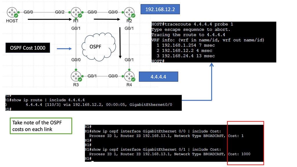
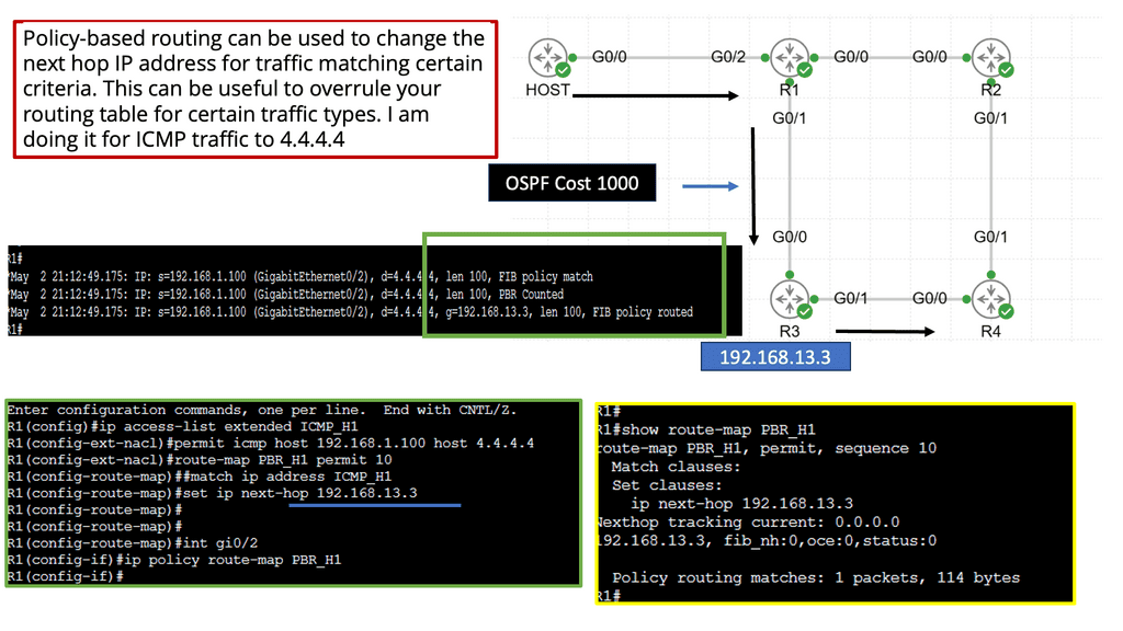
Alternatively, OpenFlow can be run in a hybrid mode. It can be deployed on a specific port, virtual local area network (VLAN), or a regular packet-forwarding pipeline. Since there is no match in the OpenFlow table, packet forwarding is equivalent to policy-based routing (PBR).

SDN and OpenFlow

OpenFlow provides granularity in determining forwarding paths (matching fields in packets) because its tables support more than destination addresses. PBR provides granularity by considering the source address when selecting the next routing hop.

In a similar way to OpenFlow, it allows network administrators to forward traffic based on non-traditional attributes, such as packet source addresses. Despite taking quite some time for network vendors to offer comparable performance for PBR-forwarded traffic, the final result was still very vendor-specific.

OpenFlow allowed us to make traffic-forwarding decisions at the same granularity as before but without vendor bias. Thus, network infrastructure capabilities could be enhanced without waiting for the following hardware version.

Example Technology: Policy-Based Routing

**The Mechanics of Policy-Based Routing**

At its core, policy-based routing enables network operators to define custom routes based on a variety of criteria such as source IP address, application type, or even specific user requirements. This flexibility is particularly valuable in scenarios where network administrators need to manage traffic efficiently across multiple paths. By creating and applying access control lists (ACLs), administrators can dictate how and where traffic should flow, optimizing network performance and ensuring compliance with organizational policies.

**Benefits of Implementing PBR**

One of the primary advantages of policy-based routing is its ability to enhance the quality of service (QoS) across a network. By prioritizing certain types of traffic—such as VoIP or video conferencing—PBR can reduce latency and improve overall communication quality. Additionally, PBR can aid in load balancing by distributing traffic evenly across available links, preventing bottlenecks and ensuring that no single path becomes overwhelmed.

**Challenges and Considerations**

While the benefits of PBR are substantial, implementing it is not without challenges. Network administrators must carefully design and test their routing policies to avoid unintended consequences, such as routing loops or security vulnerabilities. Furthermore, the complexity of managing numerous policies can increase administrative overhead. Therefore, it’s crucial for organizations to invest in training and tools that simplify the management of PBR configurations.


Real-World Applications of OpenFlow

So, what is OpenFlow? OpenFlow is an open-source communications protocol that enables remote control of network devices from a centralized controller. It is most commonly used in software-defined networking (SDN) architectures, allowing networks to be configured and managed from a single point. OpenFlow enables network administrators to programmatically control traffic flow across their networks, allowing them to respond quickly to changing traffic patterns and optimize network performance.

**The Creation of Virtual Networks**

OpenFlow will also help it create virtual networks on top of existing physical networks, allowing for more efficient and flexible network management. As a result, OpenFlow is an essential tool for building and managing modern, agile networks that can quickly and easily adapt to changing network conditions. The following post discusses OpenFlow, the operations of the OpenFlow protocol, and the OpenFlow hardware components you can use to build an OpenFlow network.

What is OpenFlow

You may find the following helpful post for pre-information:

  1. SDN Adoption Report
  2. Network Traffic Engineering
  3. BGP SDN
  4. NFV Use Cases
  5. Virtual Switch 
  6. HP SDN Controller

OpenFlow Protocol

OpenFlow history

OpenFlow started in the labs as an academic experiment. They wanted to test concepts about new protocols and forwarding mechanisms on real hardware but failed with current architectures. The challenges of changing forwarding entries in physical switches limited the project to emulations. Emulations are a type of simulation and can’t mimic an entire production network.

The requirement to test on actual hardware (not emulations) leads to separating device planes (control, data, and management plane) and introducing the OpenFlow protocol and new OpenFlow hardware components.

Highlighting SDN

Standard network technologies, consisting of switches, routers, and firewalls, have existed since the inception of networking. Data at each layer is called different things, and forwarding has stayed the same since inception. Frames and packets have been forwarded and routed using a similar approach, resulting in limited efficiency and a high maintenance cost.

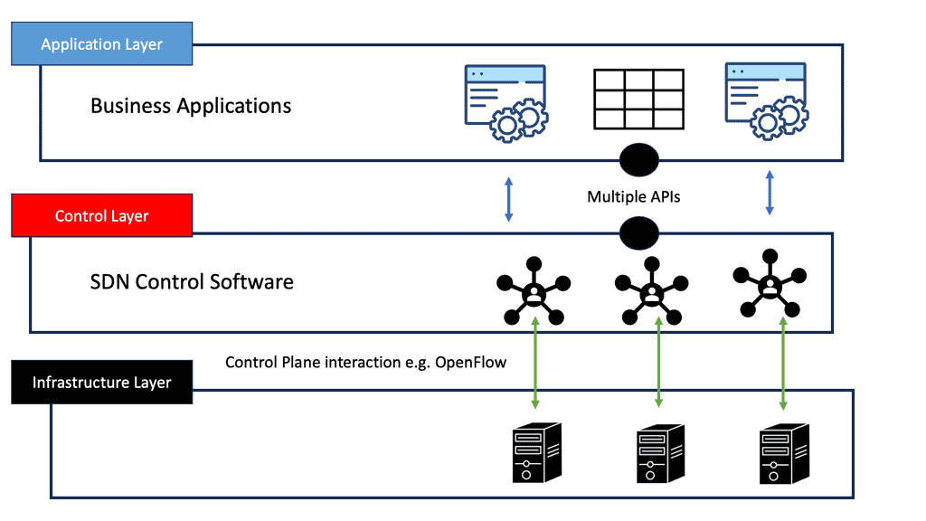
Consequently, there was a need to evolve the techniques and improve network operations, which led to the inception of SDN. SDN, often considered a revolutionary new idea in networking, pledges to dramatically simplify network control and management and enable innovation through network programmability.
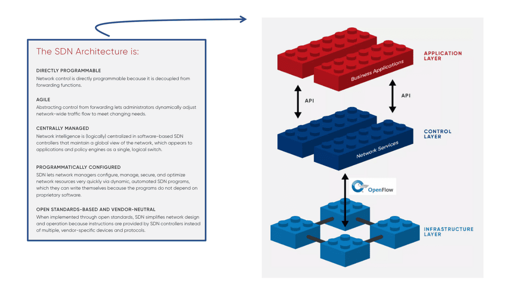
software defined networking
Diagram: Software Defined Networking (SDN). Source is Opennetworking
  • A key point: The OpenFlow Protocol versions

OpenFlow has gone through several versions, namely versions 1.0 to 1.4. OpenFlow 1.0 was the initial version of the Open Network Foundation (ONF). Most vendors initially implemented version 1.0, which has many restrictions and scalability concerns. Version 1.0 was limited and proved the ONF rushed to the market without having a complete product.

Not many vendors implemented versions 1.1 or 1.2 and waited for version 1.3, allowing per-flow meter and Provider Backbone Bridging (PBB) support. Everyone thinks OpenFlow is “open,” but it is controlled by a closed group of around 150 member organizations, forming the ONF. The ONF specifies all the OpenFlow standards, and work is hidden until published as a standard.

OpenFlow Protocol: Separation of Planes

An OpenFlow network has several hardware components that enable three independent pieces: the data plane, control plane, and management plane.

A: – The data plane

The data plane switches Protocol Data Units (PDU) from incoming ports to destination ports. It uses a forwarding table. For example, a Layer 2 forwarding table could list MAC addresses and outgoing ports. A Layer 3 forwarding table contains IP prefixes with next hops and outgoing ports. The data plane is not responsible for creating the controls necessary to forward. Instead, someone else has the job of “filling in” the data plane, which is the control plane’s function.

B: – The control plane

The control plane is responsible for giving the data plane the required information to enable it to forward. It is considered the “intelligence” of the network as it makes the decisions about PDU forwarding. Control plane protocols are not limited to routing protocols; they’re more than just BGP and OSPF. Every single protocol that runs between adjacent devices is usually a control plane. Examples include line card protocols such as BFD, STP, and LACP.

These protocols do not directly interface with the forwarding table; for example, BFD detects failures but doesn’t remove anything from the forwarding table. Instead, it informs other higher-level control plane protocols of the problem and leaves them to change the forwarding behavior.

C: – The management plane

On the other hand, protocols like OSPF and ISIS directly influence the forwarding table. Finally, the management plane provides operational access and monitoring. It permits you or “something else” to configure the device.
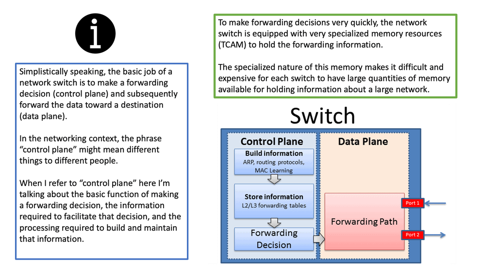
Switch functions
Diagram: Switch functions. Source is Bradhedlund

 **The Idea of OpenFlow Protocol**

OpenFlow is not revolutionary new; similar ideas have been around for the last twenty years. RFC 1925 by R. Callon presents what is known as “The Twelve Network Truths.” Section 2.11 states, “Every old idea will be proposed again with a different name and a different presentation, regardless of whether it works.” Solutions to old problems are easily dressed up in new clothes, but the problems stay the same.

Example: Use case of vendors and OpenFlow hardware.

The scalability of a central control plane will always pose challenges. We had this with the SDH/SONET and Frame Relay days. NEC and Big Switch networks tried to centralize, eventually moving as much as possible to local devices or limiting the dynamic nature and number of supported protocols.

For example, NEC permits only static port channels, and if you opt for Layer 3 IP forwarding, the only control protocol they support is ARP. Juniper implemented a scalable model with MP-BGP, retaining low-level control plane protocols on local switches. Putting all the routine easy jobs on the local switch makes the architecture more scalable.

Cisco DFA or ACI uses the same architecture. It’s also hard to do fast feedback looks and fast convergence with a centralized control plane. OpenFlow and centralized control plane-centric SDN architectures do not solve this. You may, however, see OpenFlow combined with the Open vSwitch.  Consider the Open vSwitch, also known as OVS, and the OVS bridge as the virtual switch in the data path.

  • A key point: Open vSwitch

The Open vSwitch is an open-source multi-layered switch that allows hypervisors to virtualize the networking layer. It is designed to enable network automation through programmatic extension. The OVS bridge supports standard management interfaces and protocols such as NetFlow, LACP, and 802.1ag).  This caters to many virtual machines running on one or more physical nodes. The virtual machines connect to virtual ports on virtual bridges (inside the virtualized network layer.)
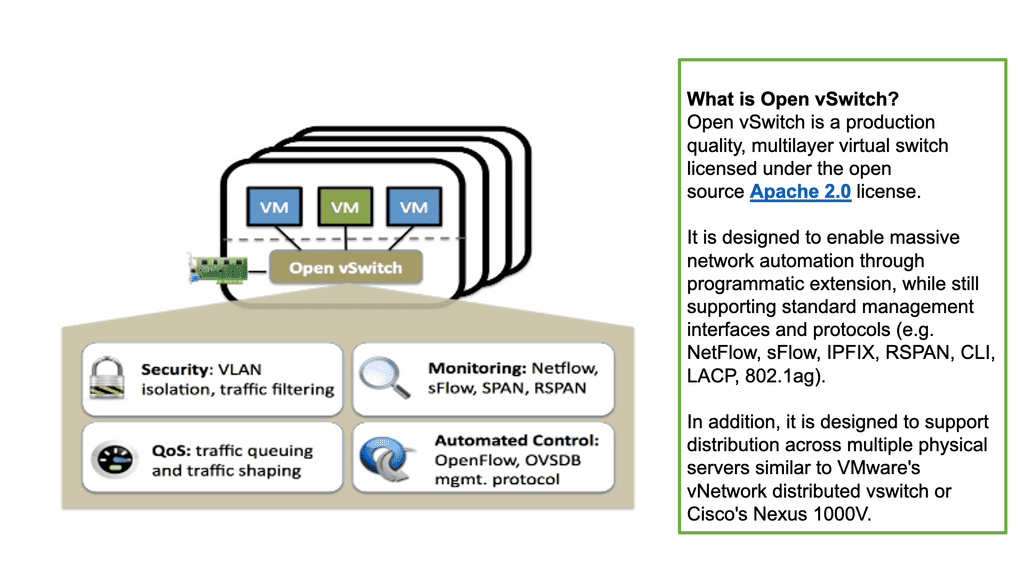
OVS bridge
Diagram: OVS Bridge: Source OpenvSwitch.
  • A key point: OpenFlow and Open Networking

Today, with many prominent vendors, we need an open interface to the forwarding plane. Many refer to this as monolithic, closed, and mainframe-like networking devices. On the other hand, a protocol such as OpenFlow. OpenFlow allows direct access to and manipulation of the forwarding plane of the network device. We can now move network control out of proprietary network switches and into open-source and locally managed control software. We were driving a new world of open networking.

OpenFlow protocol and decoupling

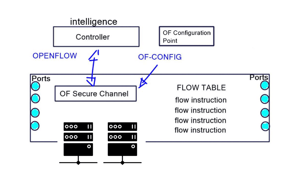
The idea of OpenFlow is straightforward. Let’s decouple the control and management plane from the switching hardware. Split the three-plane model where the dumb hardware is in one box, and the brains are in the other. The intelligence has to have a mechanism to push the forwarding entries, which could be MAC, ACL, IP prefix, or NAT rules to the local switches. The protocol used to push these entries is OpenFlow.

OpenFlow is viewed as a protocol with several instruction sets and an architecture. But it is nothing more than a Forwarding ( TCAM ) download protocol. It cannot change the switch hardware functionality. If something is supported in OpenFlow but not in the hardware, OpenFlow cannot do anything for you.

Just because OpenFlow versions allow specific matching doesn’t mean that the hardware can match those fields. For example, Juniper uses OpenFlow 1.3, which permits IPv6 handling, but its hardware does not permit matching on IPv6 addresses. 

Flow table and OpenFlow forwarding model

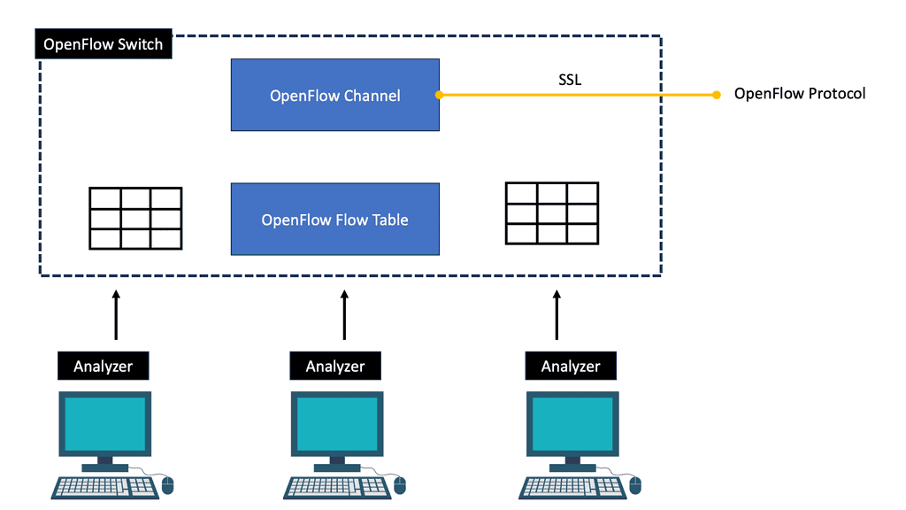
The flow table in a switch is not the same as the Forwarding Information Base (FIB). The FIB is a simple set of instructions supporting destination-based switching. The OpenFlow table is slightly more complicated and represents a sequential set of instructions matching multiple fields. It supports flow-based switching.

OpenFlow 1.0 – Single Table Model: OpenFlow hardware with low-cost switches 

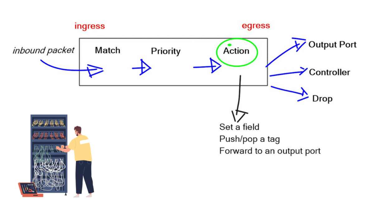
The initial OpenFlow forwarding model was simple. They based the model of OpenFlow on low-cost switches that use TCAM. Most low-cost switches have only one table that serves all of the forwarding needs of that switch. As a result, the model for the OpenFlow forwarding model was a straightforward table. First, a packet is received on an interface; we extract metadata (like incoming interface) and other header fields from the packet.

Then, the fields in the packet are matched in the OpenFlow table. Every entry in a table has a protocol field, and the match with the highest priority is the winner. Every line in the table should have a different priority; the highest-priority match determines the forwarding behavior.
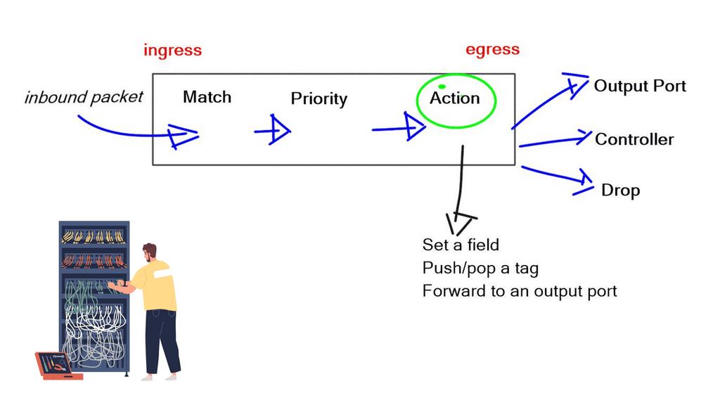
Openflow protocol
Diagram: OpenFlow protocol
  • If you have simple MAC address forwarding, i.e., building a simple bridge. All entries are already distinct. So, there is no overlap, and you don’t need to use the priority field.

Once there is a match, the packet’s action is carried out. The action could be to send to an interface, drop, or send to the controller. The default behavior of OpenFlow 1.0 would send any unmatched packets to the controller. This punting was later removed as it exposed the controller to DoS attacks. An attacker could figure out what is not in the table and send packets to that destination, completely overloading the controller.

The original OpenFlow specifications could be sent to the interface or the controller. Still, they figured out they may need to modify the packet, such as changing the TTL, setting a field, and pushing/pop tags. They realized version 1.0 was broken, and you must do more than one action on every specific packet. Multiple actions must be associated with each flow entry. This was later addressed in subsequent OpenFlow versions.

OpenFlow ports

OpenFlow has the concept of ports. Ports on an OpenFlow switch serve the same input/output purposes as any switch. From the perspective of ingress and egress traffic flows, it is no different from any other switch. For example, the ingress port for one flow might be the output port for another flow.

OpenFlow defines several standard ports, such as physical, logical, and reserved. Physical ports correspond directly to the hardware. Logical ports do not directly correspond to hardware, such as MPLS LSP, tunnel, and null interfaces.

Reserved ports are used for internal packet processing and OpenFlow hybrid switch deployments. Reserved ports are either required or optional. Required ports include ALL, CONTROLLER, TABLE, IN_PORT, and ANY. In comparison, the Optional ports include LOCAL, NORMAL, and FLOOD.

TCAM download protocol

OpenFlow is simply a TCAM download protocol. OpenFlow cannot do this if you want to create a tunnel between two endpoints. It does not create interfaces for you. Other protocols, such as OF-CONFIG, use NETCONF for this job. It is a YANG-based data model. OpenFlow protocol is used between the controller and the switch, while OF-CONFIG is used between a configuration point and the switch. A port can be added, changed, or removed in the switch configuration with OF-CONFIG, not OpenFlow.

Port changes (state) do not automatically change the direction of the flow entry. For example, a flow entry will still point to that interface if a port goes down and subsequent packets are dropped. All port changes must first be communicated to the controller so it can make changes to the necessary forwarding by downloading instructions with OpenFlow to the switches.

A variety of OpenFlow messages are used for switch-to-controller and controller-to-switch communication. We will address these in the OpenFlow Series 2 post.

OpenFlow Classifiers

OpenFlow is modeled like a TCAM, supporting several matching mechanisms. You can use any combination of packet header fields to match a packet. Possibilities to match on MAC address (OF 1.0), with wildcards (OF 1.1), VLAN and MPLS tag (OF 1.1), PBB headers (OF 1.3), IPv4 address with wild cards, ARP fields, DSCP bits. Not many vendors implement ARP field matching due to hardware restrictions. Much current hardware does not let you look deep into ARP fields. IPv6 address (OF 1.2) and IPv6 extension headers (OF1.3), Layer 4 protocol, TCP, and UDP port numbers are also supported.

Once a specific flow entry matches a packet, you can specify the number of actions. Options include output to the port type: NORMAL port for traditional processing, LOCAL PORT for the local control plane, and CONTROLLER port for sending to the controller.

In addition, you may set the OUTPUT QUEUE ID, PUSH/POP VLAN, MPLS, or PBB tags. You can even do a header rewrite, which means OpenFlow can be used to implement NAT. However, be careful with this, as you only have a limited number of flow entries on the switches. Finally, some actions might be in software, which is too slow.

OpenFlow Groups

Finally, there is an exciting mechanism where a packet can be processed through what is known as a GROUP. With OpenFlow 1.1+, the OpenFlow forwarding model included the functionality of GROUPS. Groups enhance the previous OpenFlow forwarding model. However, enhanced forwarding mechanisms like ECMP Load Balancing cannot be completed in OpenFlow 1.0. For this reason, the ONF implemented OUTPUT GROUPS.

A Group is a set of buckets, and a Bucket is a set of actions. For example, an action could be output to port, set VLAN tag, or push/pop MPLS tag. Groups can contain several buckets; bucket 1 could be sent to port 1, and bucket 2 to port 2, but it could also add a tag.

This adds granularity to OpenFlow forwarding and enables additional forwarding methods. For example, sending to all buckets in a group could be used for selective multicast, or sending to one bucket in a group could be used for load balancing across LAG or ECMP.

Final Points: OpenFlow Protocol

OpenFlow Protocol represents a significant advancement in network management, offering a more flexible, programmable, and efficient approach. Decoupling the control and forwarding plane enables centralized control, programmability, and network virtualization. With its wide range of benefits and use cases, OpenFlow Protocol is poised to revolutionize network management and pave the way for future innovations in networking technologies.

As organizations face ever-increasing network challenges, embracing OpenFlow Protocol can provide a competitive edge and drive efficiency in network operations.

Summary: OpenFlow Protocol

The introduction of the OpenFlow protocol has witnessed a remarkable revolution in the world of networking. In this blog post, we will delve into its intricacies and explore how it has transformed the way networks are managed and controlled.

Understanding OpenFlow

At its core, OpenFlow is a communication protocol that enables the separation of control and data planes in network devices. Unlike traditional networking approaches, where switches and routers make forwarding decisions, OpenFlow centralizes the control plane, allowing for dynamic and programmable network management.

The Key Components of OpenFlow

To grasp the power of OpenFlow, it is essential to understand its key components. These include the OpenFlow switch, which processes packets based on instructions from a centralized controller, and the controller, which has a comprehensive view of the network topology and makes intelligent decisions on forwarding packets.

Benefits and Advantages

OpenFlow brings forth a myriad of benefits to networking environments. Firstly, it promotes flexibility and programmability, allowing network administrators to tailor the behavior of their networks to meet specific requirements. Furthermore, it simplifies network management, as policies and configurations can be implemented centrally. Additionally, OpenFlow enables network virtualization, enhancing scalability and resource utilization.

Real-World Applications

The adoption of OpenFlow has paved the way for innovative networking solutions. Software-defined networking (SDN) is one application where OpenFlow is critical. SDN allows for dynamic network control and management, making implementing complex policies and responding to changing network conditions easier.

In conclusion, the OpenFlow protocol has brought a paradigm shift in the networking world. Its ability to separate control and data planes, along with its flexibility and programmability, has transformed how networks are designed, managed, and controlled. As technology continues to evolve, OpenFlow and its applications, such as SDN, will undoubtedly play a pivotal role in shaping the future of networking.

network traffic engineering

Network Traffic Engineering

Network Traffic Engineering

In today's interconnected world, network traffic engineering plays a crucial role in optimizing the performance and efficiency of computer networks. This blog post aims to provide a comprehensive overview of network traffic engineering, its importance, and the techniques used to manage and control traffic flow.

Network traffic engineering efficiently manages and controls the flow of data packets within a computer network. It involves analyzing network traffic patterns, predicting future demands, and implementing strategies to ensure smooth data transmission.

Bandwidth allocation is a critical aspect of traffic engineering. By prioritizing certain types of data traffic, such as VoIP or video streaming, network engineers can ensure optimal performance for essential applications. Quality of Service (QoS) mechanisms, such as traffic shaping and prioritization, allow for efficient bandwidth allocation, reducing latency and packet loss.

Load balancing distributes network traffic across multiple paths or devices, optimizing resource utilization and preventing congestion. Network traffic engineering employs load balancing techniques, such as Equal-Cost Multipath (ECMP) routing and Dynamic Multipath Optimization (DMPO), to distribute traffic intelligently. This section will discuss load balancing algorithms and their role in traffic optimization.

QoS plays a crucial role in network traffic engineering by prioritizing certain types of traffic over others. Through QoS mechanisms such as traffic shaping, prioritization, and bandwidth allocation, critical applications can receive the necessary resources while preventing congestion from affecting overall network performance.

Routing protocols like OSPF (Open Shortest Path First) and BGP (Border Gateway Protocol) play a vital role in traffic engineering. By selecting optimal paths based on metrics like bandwidth, delay, and cost, these protocols adapt to changing network conditions and direct traffic along the most efficient routes.

Network traffic engineering is an indispensable discipline for managing the complexities of modern networks. By implementing effective traffic monitoring, QoS mechanisms, load balancing, and routing protocols, organizations can optimize network performance, improve user experience, and ensure seamless connectivity in the face of evolving traffic patterns and demands.

Highlights: Network Traffic Engineering

### Understanding Network Traffic Engineering

In the digital age, where seamless connectivity is crucial, network traffic engineering plays a pivotal role in ensuring efficient data flow across the internet. But what exactly is network traffic engineering? It involves the process of optimizing and managing data traffic on a network to improve performance, reliability, and speed. By employing various techniques and tools, network administrators can control the flow of data to prevent congestion, reduce latency, and enhance the overall user experience.

### The Importance of Efficient Network Traffic Management

Efficient network traffic management is essential in today’s fast-paced digital world. With the rise of streaming services, online gaming, and remote work, networks are under constant pressure to deliver data quickly and reliably. Traffic engineering helps avoid bottlenecks by rerouting data along less congested paths, akin to finding alternative routes during rush hour. This not only improves speed but also ensures that critical applications receive the bandwidth they require, enhancing productivity and user satisfaction.

### Techniques and Tools Used in Traffic Engineering

Network traffic engineering employs a variety of techniques and tools to achieve optimal performance. One common method is load balancing, which distributes data across multiple servers to prevent any single server from becoming overwhelmed. Additionally, Quality of Service (QoS) protocols prioritize certain types of traffic, ensuring that time-sensitive data, like video calls or financial transactions, are delivered promptly. Advanced software and analytics tools also provide real-time insights, allowing network administrators to make informed decisions and adjustments as needed.

### Challenges in Network Traffic Engineering

While network traffic engineering offers numerous benefits, it also presents several challenges. The dynamic nature of network traffic requires continuous monitoring and adaptation. Moreover, as networks grow in size and complexity, managing traffic becomes increasingly difficult. Cybersecurity threats add another layer of complexity, as engineers must balance traffic optimization with robust security measures to protect sensitive data from cyberattacks.

Understanding Network Traffic Engineering:

Network traffic engineering involves the analysis, modeling, and control of network traffic to maximize efficiency and reliability. It encompasses various aspects such as traffic measurement, traffic prediction, routing protocols, and quality of service (QoS) management. By carefully managing network resources, traffic engineering aims to minimize delays, maximize throughput, and ensure seamless communication.

  • Congestion Management Techniques

Congestion is a common occurrence in networks, leading to degraded performance and delays. Various techniques are employed in network traffic engineering to manage congestion effectively. These include traffic shaping, where data flows are regulated to prevent sudden surges, and prioritization of traffic based on quality of service (QoS) requirements. Additionally, load balancing techniques distribute traffic across multiple paths to prevent bottlenecks and ensure optimal resource utilization.

  • Route Optimization Strategies

Efficient route selection is a critical aspect of network traffic engineering. By utilizing routing protocols and algorithms, engineers can determine the most optimal paths for data transmission. This involves considering factors such as network latency, available bandwidth, and the overall health of network links. Dynamic routing protocols, such as OSPF and BGP, continuously adapt to changes in network conditions, ensuring that traffic is routed through the most efficient paths.

  • Traffic Engineering in the Era of SDN

Software-defined networking (SDN) has revolutionized network traffic engineering by introducing programmability and centralized control. With SDN, network engineers can dynamically configure and manage traffic flows, allowing for more agile and responsive networks. By leveraging technologies like OpenFlow, SDN enables granular traffic engineering capabilities, empowering network administrators to efficiently allocate network resources and adapt to changing demands.

Key Traffic Engineering Points

-Traffic Measurement and Analysis: Accurate measurement and analysis of network traffic patterns are fundamental to effective traffic engineering. By capturing and analyzing traffic data, network administrators gain insights into usage patterns, peak hours, and potential bottlenecks. This information helps in making informed decisions regarding network optimization and resource allocation.

-Traffic Prediction and Forecasting: Network operators must anticipate future traffic patterns. Through statistical analysis and predictive modeling, traffic engineers can forecast demand and plan network upgrades accordingly. By staying ahead of the curve, they ensure that network capacity keeps up with increasing data demands.

-Routing Optimization: Efficient routing is at the core of network traffic engineering. Through intelligent routing protocols and algorithms, traffic engineers optimize the flow of data across networks. They consider factors such as link utilization, latency, and available bandwidth to determine the most optimal paths for data transmission. This helps minimize congestion and ensure reliable communication.

-Prioritization and Resource Allocation: Network traffic engineering involves prioritizing different types of traffic based on their importance. Critical services such as voice and video can be prioritized by allocating resources accordingly, ensuring smooth and uninterrupted transmission. QoS mechanisms like traffic shaping, traffic policing, and packet scheduling help achieve this.

-Load Balancing: Load balancing is another crucial aspect of QoS management. By distributing traffic across multiple paths, network engineers prevent individual links from becoming overloaded. This improves overall network performance and enhances reliability and fault tolerance.

google cloud routes

Traffic Engineering: Cloud Data Centers

Understanding VPC Networking

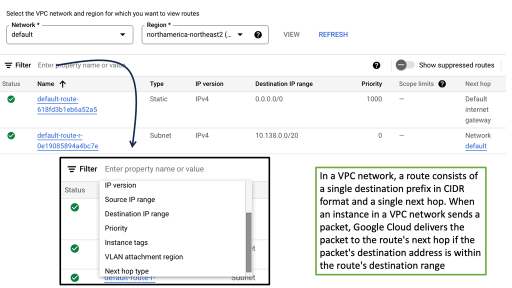
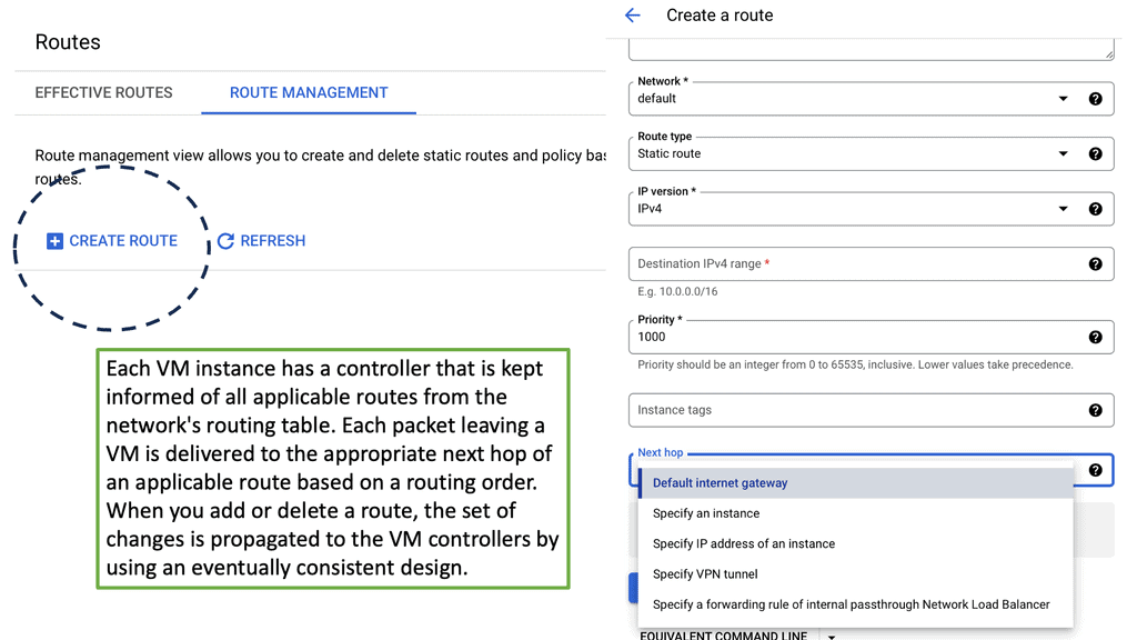
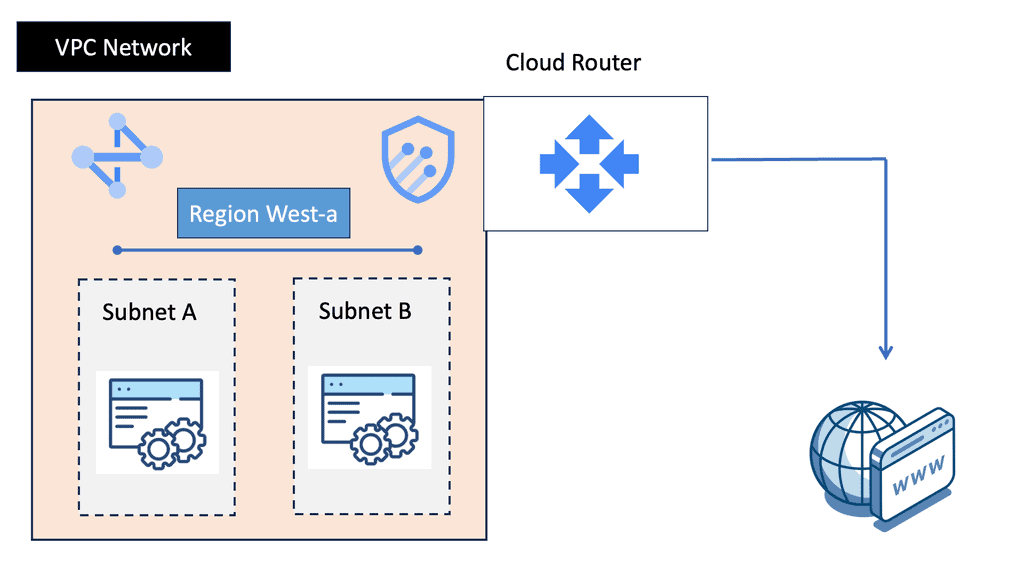
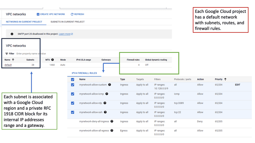
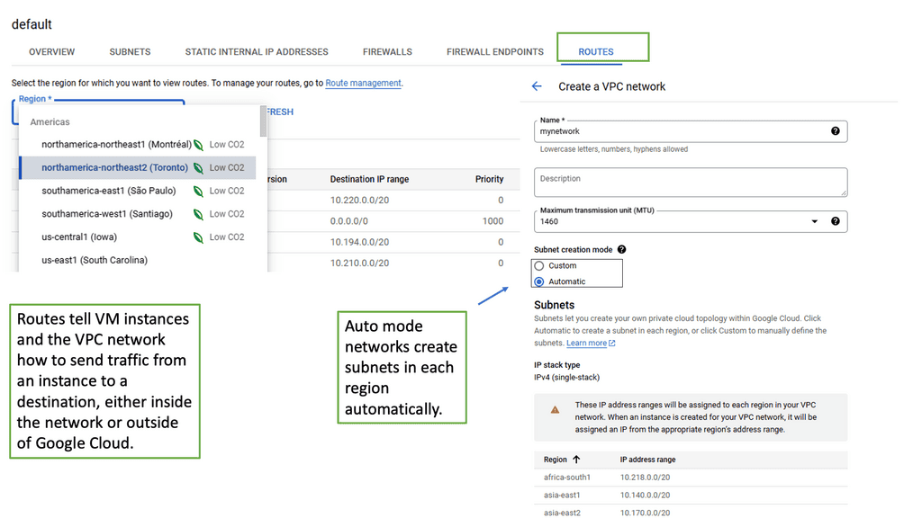
Before we dive into the specifics of VPC networking in Google Cloud, let’s establish a foundation of understanding. A Virtual Private Cloud (VPC) is a virtual network dedicated to a specific Google Cloud project. It provides an isolated and secure environment where resources can be created, managed, and interconnected. Within a VPC, you can define subnets, set up IP ranges, and configure firewall rules to control traffic flow.

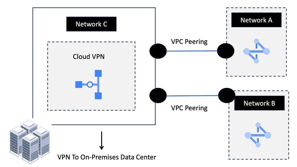
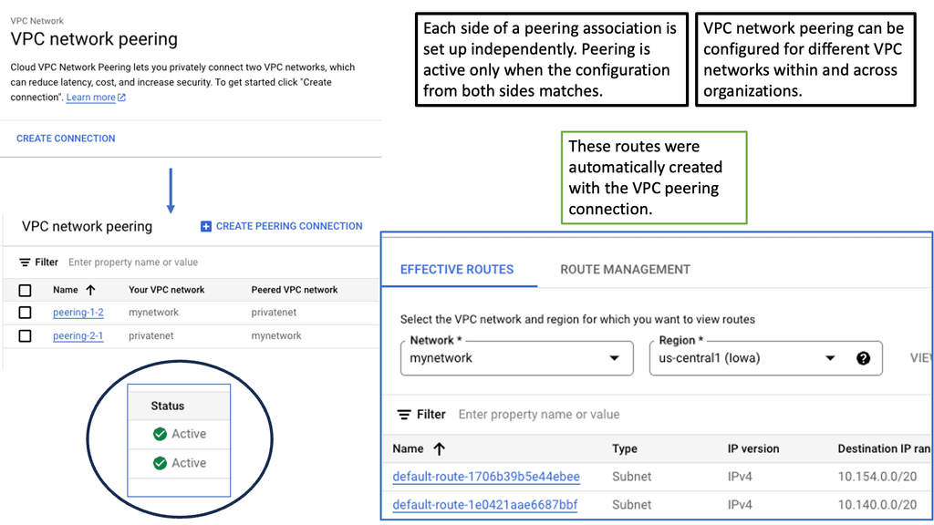
Google Cloud’s VPC networking offers a range of powerful features that enhance network management and security. One notable feature is the ability to create and manage multiple VPCs, allowing for logical separation of resources based on different requirements. Additionally, VPC peering enables communication between VPCs, even across different projects or regions. This flexibility empowers organizations to build scalable and complex network architectures.

VPC Peerings

Understanding VPC Peerings

VPC Peerings, or Virtual Private Cloud Peerings, are a mechanism that allows different Virtual Private Cloud networks to communicate with each other securely. This enables seamless connectivity between disparate networks, facilitating efficient data transfer and resource sharing. In Google Cloud, VPC Peerings play a pivotal role in creating robust and scalable network architectures.

VPC Peerings offer a multitude of benefits for organizations leveraging Google Cloud. Firstly, they eliminate the need for complex VPN setups or costly physical connections, as VPC Peerings enable direct network communication. Secondly, VPC Peerings provide a secure and private channel for data transfer, ensuring confidentiality and integrity. Additionally, they enable organizations to expand their network reach and collaborate effortlessly across various projects or regions.

Google Load Balancers

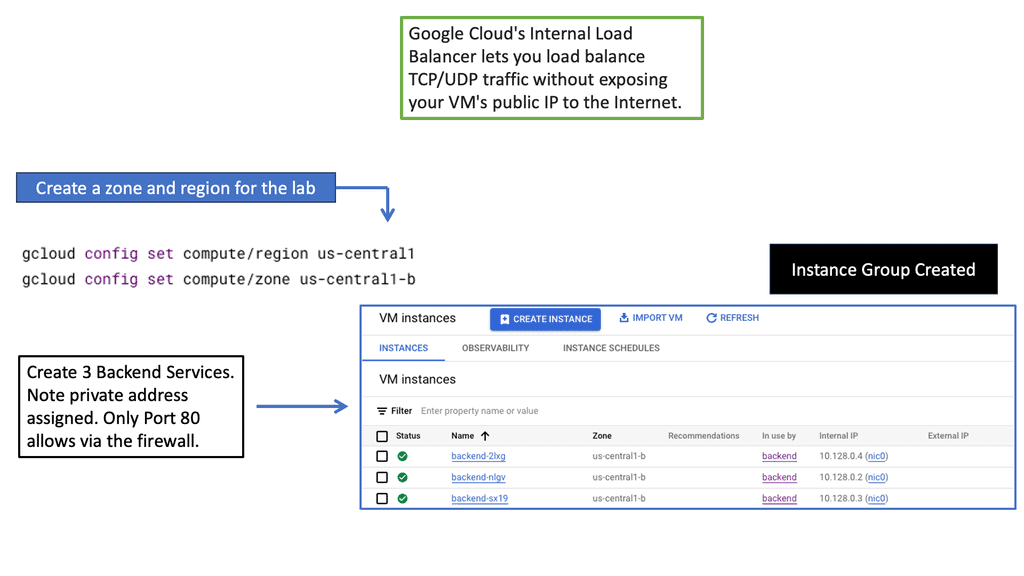
Load balancers are essential components in distributed systems that evenly distribute incoming network traffic across multiple servers or instances. This distribution ensures that no single server is overwhelmed, resulting in improved response times and reliability. Google Cloud offers two types of load balancers: network and HTTP load balancers.

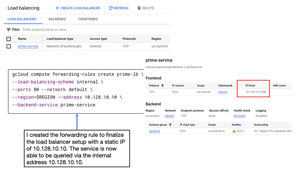
Network Load Balancers: Network load balancers operate at Layer 4 of the OSI model, meaning they distribute traffic based on IP addresses and ports. They are ideal for protocols such as TCP and UDP, providing low-latency and high-throughput load balancing. Setting up a network load balancer in Google Cloud involves creating an instance group, configuring health checks, and defining forwarding rules.

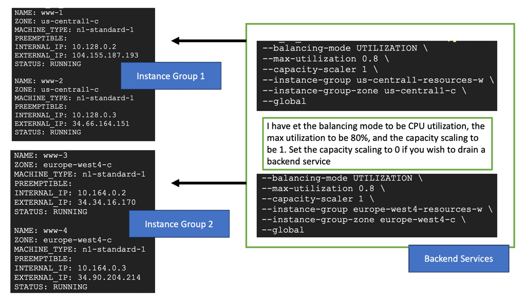
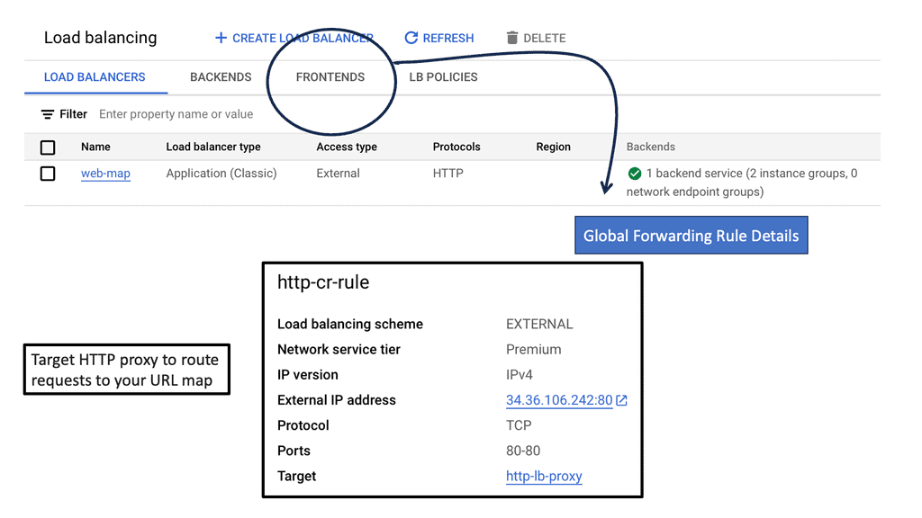
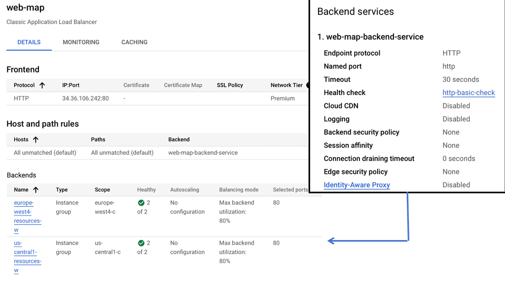
HTTP Load Balancers: HTTP load balancers, on the other hand, operate at Layer 7 and can intelligently distribute traffic based on HTTP/HTTPS requests. This allows for advanced features like session affinity, content-based routing, and SSL offloading. Configuring an HTTP load balancer with Google Cloud involves creating a backend service, defining a backend bucket or instance group, and configuring URL maps and target proxies.

Cross Regions Load Balancing

### Understanding Cross-Region Load Balancing

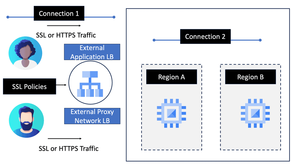
Cross-region load balancing is designed to distribute traffic across multiple data centers located in different geographical regions. This strategy maximizes resource utilization, minimizes latency, and provides seamless failover capabilities. By deploying applications across various regions, businesses can ensure that their services remain available, even in the event of a regional outage. Google Cloud offers robust cross-region HTTP load balancing solutions that allow businesses to deliver high availability and reliability for their users worldwide.

### Features of Google Cloud Load Balancing

Google Cloud’s load balancing services come packed with features that make it a top choice for businesses. These include global load balancing with a single IP address, SSL offloading for better security and performance, and intelligent routing based on proximity and performance metrics. Google Cloud also provides real-time monitoring and logging, enabling businesses to gain insights into traffic patterns and optimize their infrastructure accordingly. These features collectively enhance the performance and reliability of web applications, ensuring a seamless user experience.

### Setting Up Cross-Region Load Balancing on Google Cloud

Implementing cross-region load balancing on Google Cloud is straightforward, thanks to its user-friendly interface and comprehensive documentation. Businesses can start by defining their backend services and specifying the regions they want to include in their load balancing setup. Google Cloud then automatically manages the distribution of traffic, ensuring optimal performance and resource utilization. Additionally, businesses can customize their load balancing rules to accommodate specific requirements, such as session affinity or custom failover strategies.

cross region load balancing

Network Policies & Kubernetes

The Anatomy of a Network Policy

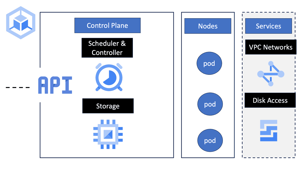
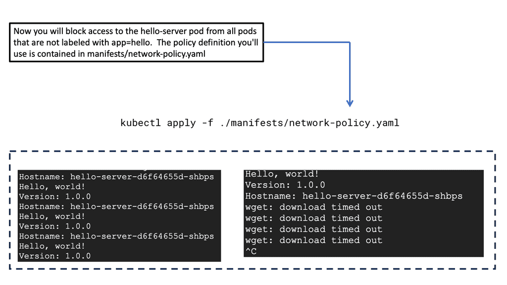
A GKE Network Policy is essentially a set of rules defined by Kubernetes that dictate what type of traffic is allowed to or from your pods. These policies are defined in YAML files and can specify traffic restrictions based on IP blocks, ports, and pod labels. Understanding the structure of these policies is fundamental to leveraging their full potential. By focusing on selectors and rules, you can create policies that are both specific and flexible, allowing for precise control over network traffic.

### Implementing Traffic Engineering with Network Policies

Network traffic engineering with GKE Network Policies involves designing your network flow to optimize performance and security. By using these policies, you can segment your network traffic, ensuring that sensitive data is only accessible to authorized pods. This segmentation can help minimize the risk of data breaches and ensure compliance with regulatory requirements. Additionally, you can use network policies to manage traffic load, ensuring that critical services receive the bandwidth they require.

### Best Practices for Using GKE Network Policies

When implementing GKE Network Policies, it’s important to follow best practices to ensure efficiency and security:

1. **Start with a Default Deny Policy:** Begin by denying all traffic and then gradually open up only the necessary paths. This minimizes the risk of unintentional exposure.

2. **Use Pod Labels Effectively:** Ensure your pod labels are well-organized and meaningful, as these are critical for creating effective network policies.

3. **Regularly Review and Update Policies:** As your applications evolve, so should your network policies. Regular audits and updates will ensure they continue to meet your security and performance needs.

Kubernetes network policy

On-Premises Traffic Engineering

Recap Technology: Router on a Stick

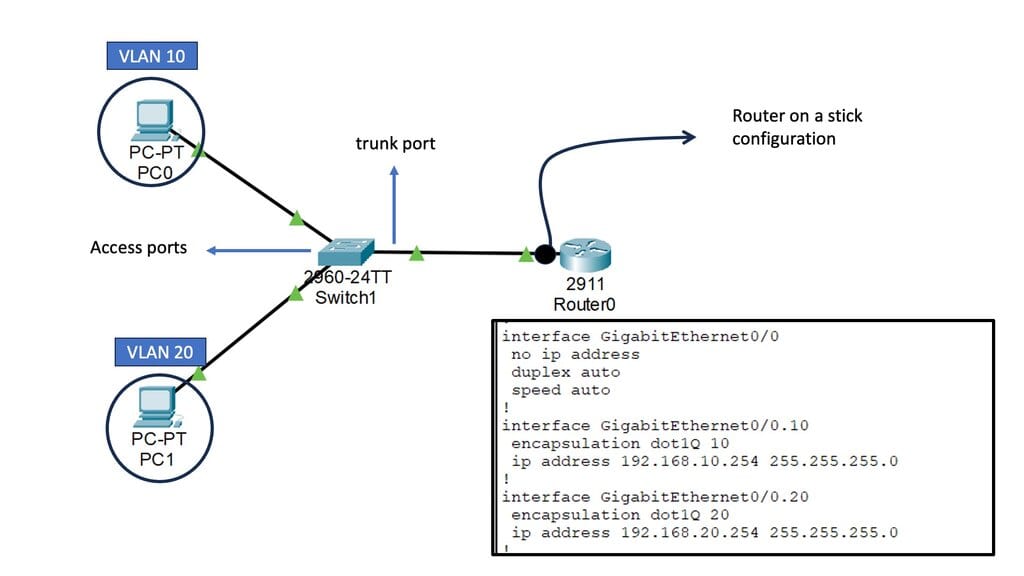
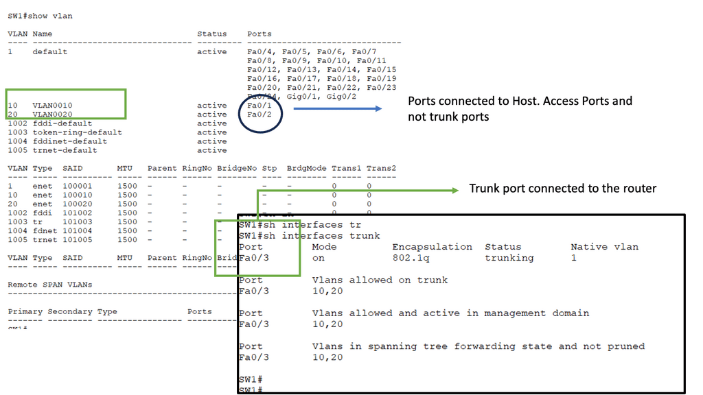
A router on a stick is a networking method that allows for the virtual segmentation of a physical network into multiple virtual local area networks (VLANs). By utilizing a single physical interface on a router, multiple VLANs can be connected and routed between each other, enabling efficient traffic flow within a network.

Several critical components must be in place to implement a router on a stick. Firstly, a router capable of supporting VLANs and subinterfaces is required. Additionally, a managed switch that supports VLAN tagging is necessary. The logical separation of networks is achieved by configuring the router with subinterfaces and assigning specific VLANs to each. The managed switch, on the other hand, facilitates the tagging of VLANs on the physical ports connected to the router.

router on a stick

What is Policy-Based Routing?

Policy-based routing (PBR) allows network administrators to route traffic based on predefined policies or criteria selectively. Unlike traditional routing methods relying solely on destination IP addresses, PBR considers additional factors such as source IP addresses, protocols, and packet attributes. Thus, PBR offers greater flexibility and control over network traffic flow.

To implement policy-based routing, several steps need to be followed. Firstly, administrators must define the policies that will govern traffic routing decisions. These policies can be based on various parameters, including source or destination IP addresses, transport layer protocols, or packet attributes such as DSCP markings.

Once the policies are defined, they must be associated with specific routing actions, such as forwarding traffic to a particular next-hop or routing table. Finally, the policy-based routing configuration must be applied to relevant network devices, ensuring the desired traffic behavior.

Generic Traffic Engineering

Network traffic engineering involves optimizing and managing traffic flows to enhance overall performance. It encompasses various techniques and strategies for controlling and shaping the flow of data packets, minimizing congestion, and maximizing network efficiency.

Network traffic engineering involves analyzing, monitoring, and controlling traffic to achieve desired performance. It aims to maximize efficiency, minimize congestion, and optimize resource utilization. Network traffic engineering ensures seamless communication and reliable connectivity by intelligently managing data flows.

a) Traffic Analysis: This technique involves studying traffic patterns, identifying bottlenecks, and analyzing network behavior. By understanding the data flow dynamics, network engineers can make informed decisions to enhance performance and mitigate congestion.

b) Quality of Service (QoS): QoS mechanisms prioritize different types of traffic based on predefined criteria. This ensures critical applications receive sufficient bandwidth and low-latency connections while less important traffic is appropriately managed.

c) Load Balancing: Load balancing distributes network traffic across multiple paths or devices, preventing resource overutilization and congestion. It optimizes available capacity, ensuring efficient data transmission and minimizing delays.

Example: Multipoint GRE

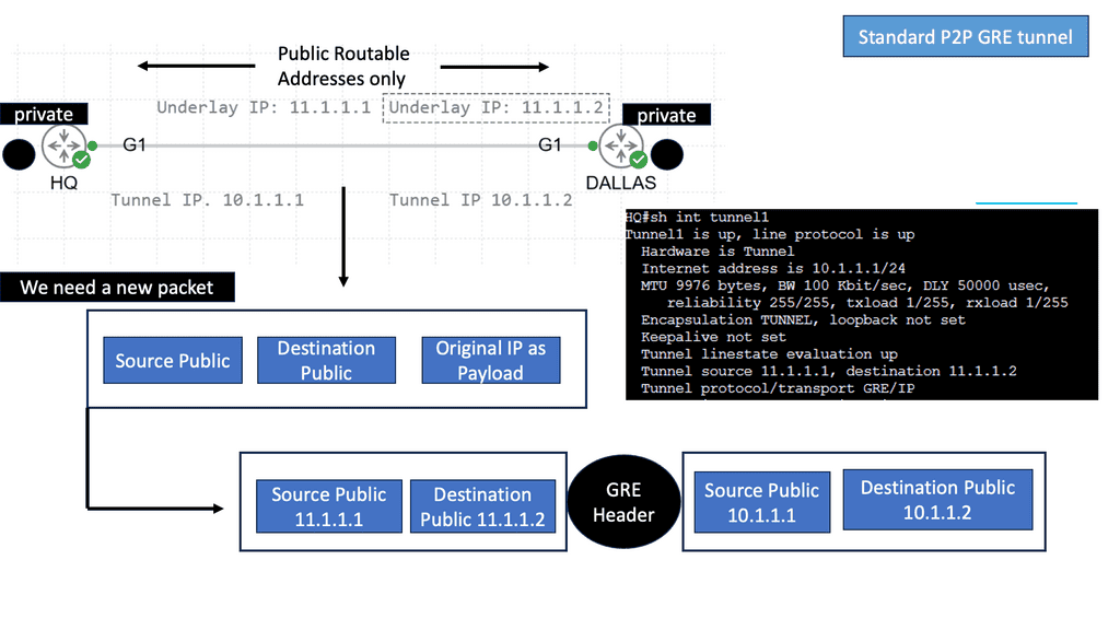
When establishing secure communication tunnels over IP networks, GRE (Generic Routing Encapsulation) protocols play a crucial role. Among the variations of GRE, two commonly used types are multipoint GRE and point-to-point GRE. 

As the name suggests, point-to-point GRE provides a direct and dedicated connection between two endpoints. It allows for secure and private communication between these points, encapsulating the original IP packets within GRE headers. This type of GRE is typically employed when a direct, point-to-point link is desired, such as connecting two remote offices or establishing VPN connections.

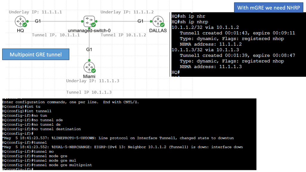
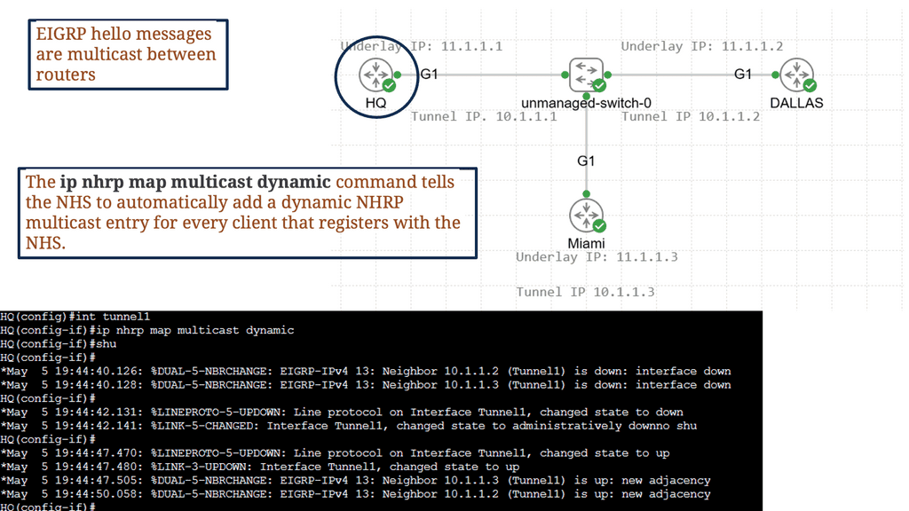
Unlike point-to-point GRE, multipoint GRE enables communication between multiple endpoints within a network. It acts as a hub, allowing various sites or hosts to connect and exchange data securely. Multipoint GRE simplifies network design by eliminating the need for individual point-to-point connections. It is an efficient and scalable solution for scenarios like hub-and-spoke networks or multicast applications.

Example: Understanding NHRP

NHRP, at its core, is a protocol used to discover the next hop for reaching a particular destination within a VPN. It acts as a mediator between the client and the server, enabling seamless communication by resolving IP addresses to the appropriate physical addresses. By doing so, NHRP eliminates the need for unnecessary broadcasts and optimizes routing efficiency.

To comprehend NHRP’s operation, let’s break it down into three key steps: registration, resolution, and caching. A client registers its tunnel IP address with the NHRP server during registration. In the resolution phase, the client queries the NHRP server to obtain the physical address of the desired destination. Finally, the caching mechanism allows subsequent requests to be resolved locally, reducing network overhead.


IPv6 Traffic Engineering

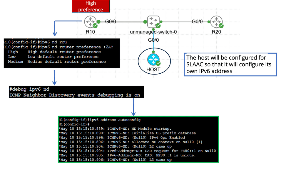
Understanding Router Advertisement (RA)

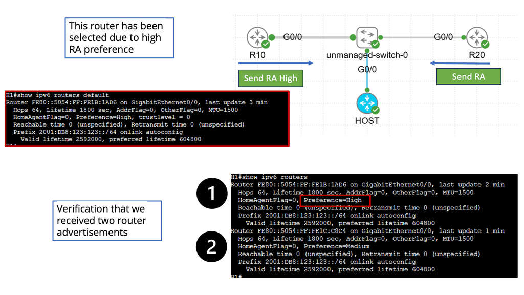
RA is a critical component in IPv6 network configuration, allowing routers to inform hosts about their presence and available services. By sending periodic RAs, routers enable hosts to autoconfigure their IPv6 addresses and determine the default gateway for outgoing traffic.

Router Advertisement Preference refers to the mechanism by which hosts select the most suitable router among the multiple routers available in a network. This preference level is determined by various factors, including the router’s Lifetime, Router Priority, and Prefix Information Options.

Factors Influencing Router Advertisement Preference:

a) Router Lifetime: The Lifetime value indicates the validity duration of the advertised prefixes. Hosts prioritize routers with longer Lifetime values, as they provide stable connectivity.

b) Router Priority: Hosts prefer routers with higher priority values during RA selection. This allows for more granular control over which routers are chosen as default gateways.

c) Prefix Information Options: Specific Prefix Information Options, such as Autonomous Flag and On-Link Flag, influence the router preference. Hosts evaluate these options to determine the router’s capability for autonomous address configuration and on-link subnet connectivity.

Traffic Engineering with Routing protocols

Routing protocol traffic engineering is the art of intelligently managing network traffic flow. It involves the manipulation of routing paths to achieve specific objectives, such as minimizing latency, maximizing bandwidth utilization, or enhancing network resilience. By strategically steering traffic, network administrators can overcome congestion, bottlenecks, and other performance limitations.

Traffic Engineering with OSPF: OSPF (Open Shortest Path First) is a widely used routing protocol that supports traffic engineering capabilities. It allows network administrators to influence traffic paths by manipulating link metrics, enabling the establishment of preferred routes and load balancing across multiple links.

MPLS Traffic Engineering: Multiprotocol Label Switching (MPLS) is another powerful tool in traffic engineering. By assigning labels to network packets, MPLS enables the creation of explicit paths that bypass congested links or traverse paths with specific quality of service (QoS) requirements. MPLS traffic engineering provides granular control and flexibility in routing decisions.

BGP Traffic Engineering: Border Gateway Protocol (BGP) is primarily used in large-scale networks and internet service provider (ISP) environments. BGP traffic engineering allows network operators to manipulate BGP attributes to influence route selection and steer traffic based on various criteria, such as AS path length, local preference, or community values.

Traffic Engineering with EIGRP

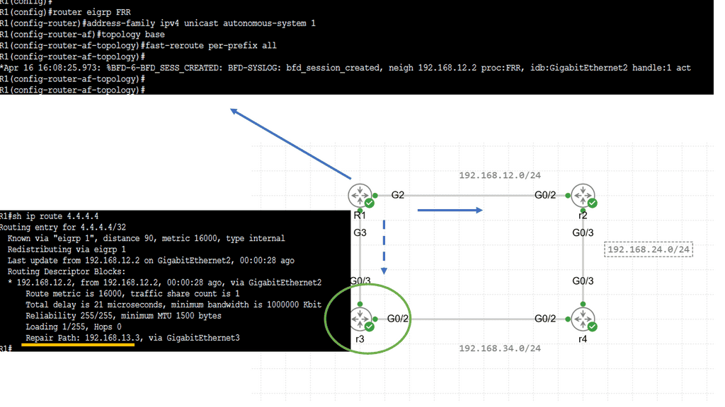
Before diving into EFRR, let’s briefly overview the Enhanced Interior Gateway Routing Protocol (EIGRP). Developed by Cisco, EIGRP is a routing protocol widely used in enterprise networks. It provides fast convergence, load balancing, and scalability, making it a popular choice among network administrators.

Fast Reroute (FRR) is a mechanism that enables routers to swiftly reroute traffic in the event of a link or node failure. Within the realm of EIGRP, EFRR refers to the specific implementation of FRR. EFRR allows for sub-second convergence by precomputing backup paths, significantly reducing the impact of network failures.

EIGRP LFAExample: BGP Traffic Engineering with DMVPM

**Understanding DMVPN and Its Role in Modern Networks**

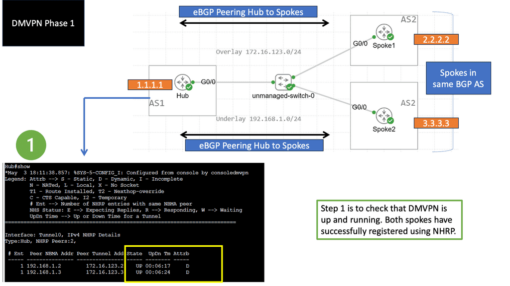
DMVPN is a Cisco-developed solution that simplifies the creation of scalable and dynamic VPNs. It enables secure communication between multiple sites without the need for static tunnels, significantly reducing configuration overhead. In a DMVPN setup, BGP can be utilized to dynamically adjust traffic paths, ensuring efficient use of available bandwidth and enhancing network resilience. This section delves into the intricacies of DMVPN and how it complements BGP in network traffic engineering.

**BGP Techniques for Traffic Optimization**

Utilizing BGP for traffic engineering involves various techniques, such as route reflection, path selection, and prefix prioritization. By controlling these elements, network administrators can influence the direction of data traffic to avoid congestion and minimize latency. This section provides a detailed overview of these techniques, offering practical examples and best practices for optimizing network performance in a DMVPN environment.

DMVPN Phase 2 Traffic Engineering

Resolutions triggered by the NHRP

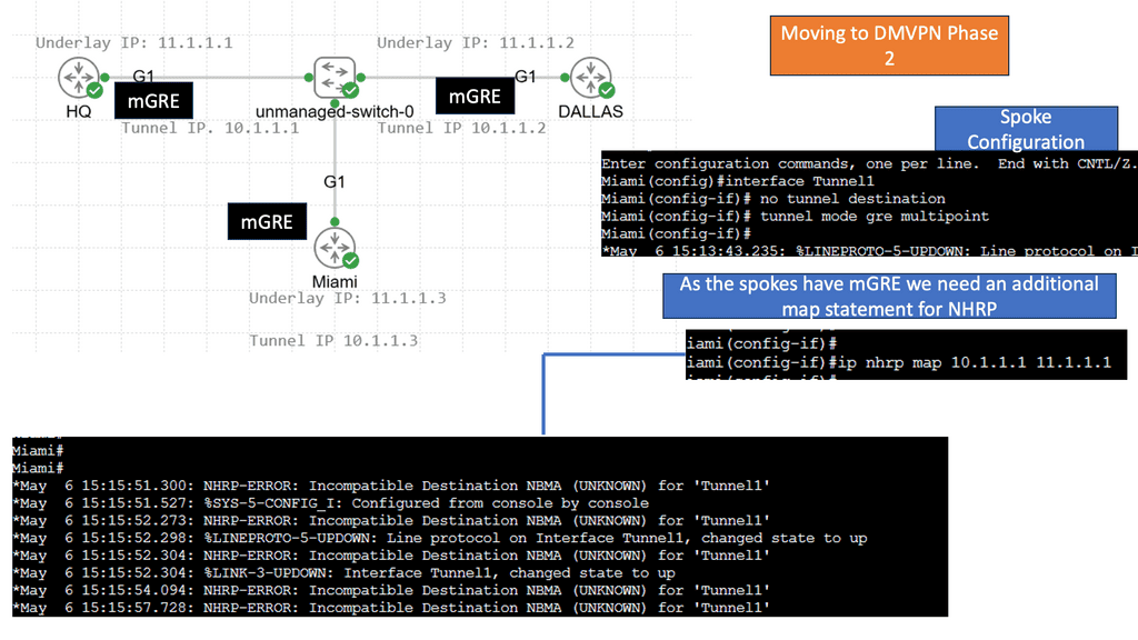
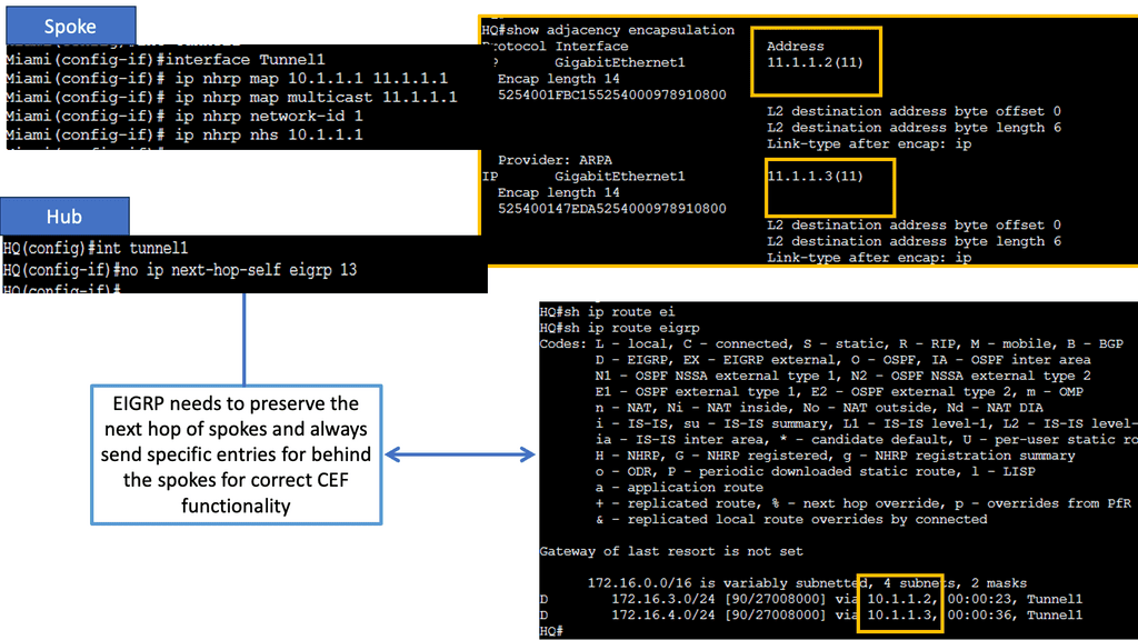
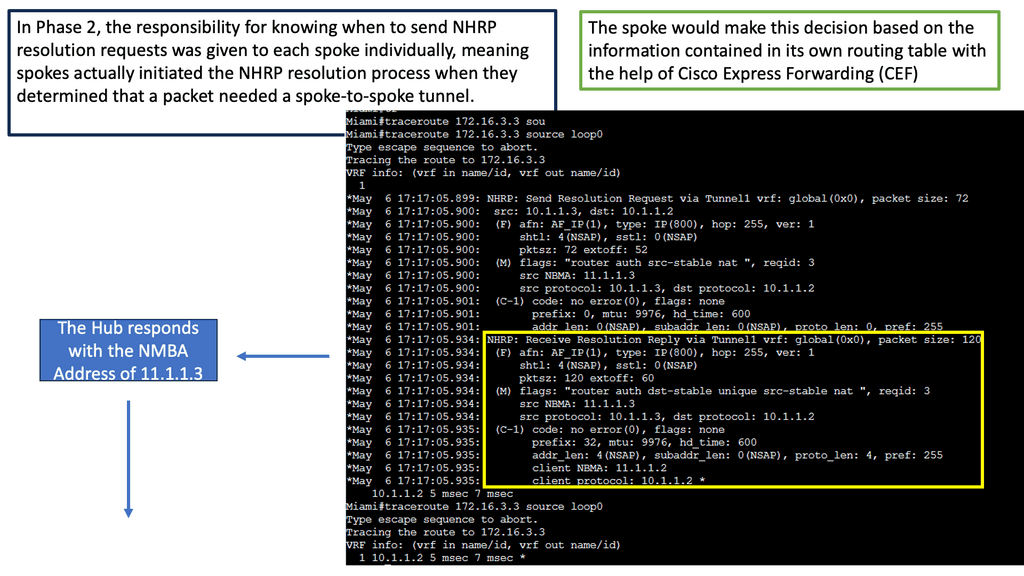
Learning the mapping information required through NHRP resolution creates a dynamic spoke-to-spoke tunnel. How does a spoke know how to perform such a task? As an enhancement to DMVPN Phase 1, spoke-to-spoke tunnels were first introduced in Phase 2 of the network. Phase 2 handed responsibility for NHRP resolution requests to each spoke individually, which means that spokes initiated NHRP resolution requests when they determined a packet needed a spoke-to-spoke tunnel. Cisco Express Forwarding (CEF) would assist the spoke in making this decision based on information contained in its routing table.

Network Traffic Engineering Tools

Network Monitoring and Analysis: Network monitoring tools, like packet sniffers and flow analyzers, provide valuable insights into traffic patterns, bandwidth utilization, and performance metrics. These tools help network engineers identify bottlenecks, analyze traffic behavior, and make informed decisions for traffic optimization.

a) Traffic Analysis Tools

Traffic analysis tools provide valuable insights into network traffic patterns, helping administrators identify potential bottlenecks, anomalies, and security threats. These tools often use packet sniffing and flow analysis techniques to capture and analyze network traffic data.

b) Traffic Optimization Tools

Traffic optimization tools focus on improving network performance by optimizing network resources, reducing congestion, and balancing traffic loads. These tools use algorithms and heuristics to intelligently route traffic, allocate bandwidth, and manage Quality of Service (QoS) parameters.

c) Traffic Monitoring and Reporting Tools

Monitoring and reporting tools are essential for network administrators to gain real-time visibility into network traffic. These tools provide comprehensive dashboards, visualizations, and reports that help identify network usage patterns, track performance metrics, and troubleshoot issues promptly.

d) Traffic Simulation and Modeling Tools

Traffic simulation and modeling tools enable network engineers to assess the impact of changes in network configurations before implementation. By simulating various scenarios and traffic patterns, these tools help optimize network designs, plan capacity upgrades, and evaluate the effectiveness of traffic engineering strategies.

Traceroute – Understanding Network Paths

**What is Traceroute? A Peek Behind the Scenes**

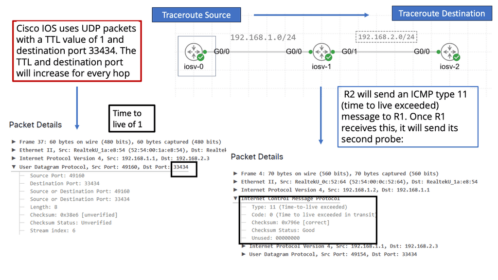
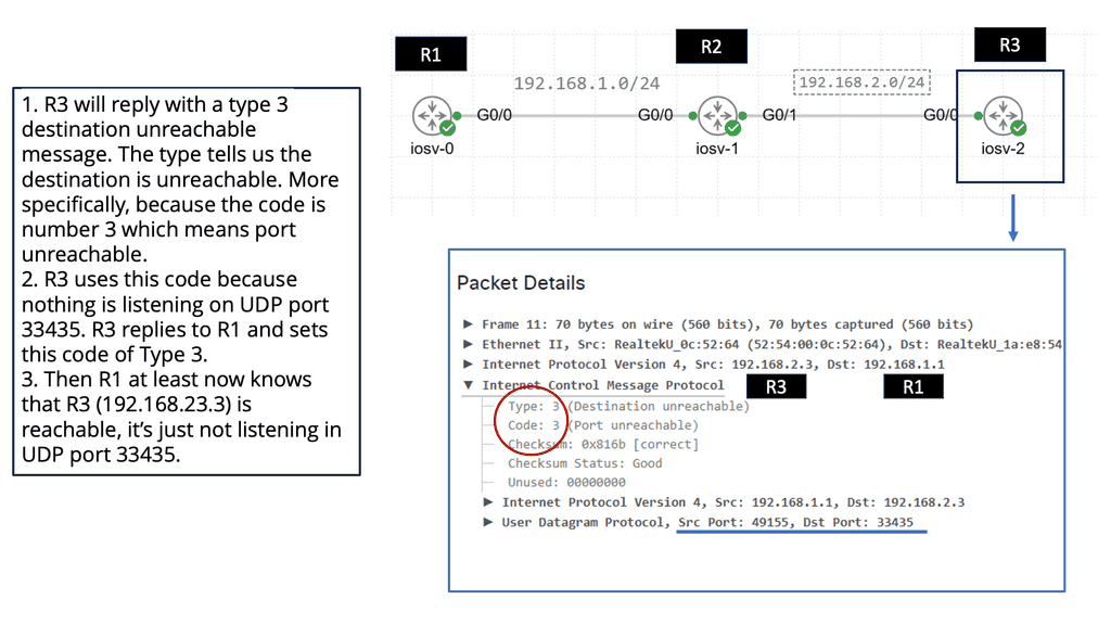
Traceroute is a network diagnostic command-line tool used to track the path data packets take from a source to their destination across a network. By sending packets with gradually increasing time-to-live (TTL) values, traceroute maps out each hop along the route, revealing the IP addresses and response times of each intermediate device. This detailed map helps identify where delays or failures occur, making it an invaluable resource for network administrators and IT professionals.

**How Traceroute Works: Breaking Down the Mechanics**

The process begins with traceroute sending a series of packets with a TTL value of one. The first router along the path decrements the TTL, and when it reaches zero, the router sends back an ICMP “Time Exceeded” message. Traceroute then increases the TTL by one and sends another packet, repeating the process until the packets reach the destination. By collecting the time it takes for each “Time Exceeded” message to return, traceroute provides a list of hops, each with its associated latency.

**Practical Applications of Traceroute: Beyond Troubleshooting**

While traceroute is primarily used for diagnosing network issues, its applications extend beyond troubleshooting. Understanding the path data takes can help optimize network performance, plan network expansions, and even assess the impact of routing changes. Additionally, traceroute can be used for educational purposes, offering insights into the structure and dynamics of the internet.

Network Flow Model

In a computer network, an important function is to carry traffic efficiently, given the routing paradigm in place. Traffic engineering achieves this efficiency. Network flow models are used for network traffic engineering and can help determine routing decisions. Network Traffic engineering (TE) is the engineering of paths that can carry traffic flows that vary from those chosen automatically by the routing protocol(s) used in that network.

Therefore, we can engineer the paths that better suit our application. We can do this in several ways, such as standard IP routing, MPLS, or OpenFlow protocol. When considering network traffic engineering and MPLS OpenFlow, let’s start with the basics of traffic engineering and MPLS networking.
**Traffic Engineering Examples**

Traffic engineering is not an MPLS-specific practice; it is a general practice. Implementing traffic engineering can be as simple as tweaking IP metrics on interfaces or as complex as running an ATM PVC full-mesh and optimizing PVC paths based on traffic demands. Using MPLS, traffic engineering techniques (like ATM PVC placement) are merged with IP routing techniques to achieve connection-oriented traffic engineering. With MPLS, traffic engineering is just as practical as with ATM, but without some drawbacks of IP over ATM.

**Decoupling Routing and Forwarding**

A hop-by-hop forwarding paradigm is used in IP routing. When an IP packet arrives at a router, it is checked for the destination address in the IP header, a route lookup is performed, and the packet is forwarded to the next hop. The packet is dropped if there is no route. Each hop repeats this process until the packet reaches its destination.

Nodes in MPLS networks also forward packets hop by hop, but this forwarding is based on fixed-length labels. MPLS applications such as traffic engineering are enabled by this ability to decouple packet forwarding from IP headers.

Understanding MPLS Forwarding

MPLS, or Multi-Protocol Label Switching, is used in telecommunications networks to efficiently direct data packets based on labels rather than traditional IP routing. This section will provide a clear and concise overview of MPLS forwarding, explaining its purpose, components, and how it differs from conventional routing methods.

Implementing MPLS forwarding requires careful planning and configuration. This section will provide step-by-step guidance on deploying MPLS forwarding in a network infrastructure. From designing the MPLS network architecture to configuring routers and establishing Label Switched Paths (LSPs), readers will receive practical insights and best practices for a successful implementation.

Example Technology: Next-Hop Resolution Protocol

1: NHRP, or Next Hop Resolution Protocol, is vital in dynamic address resolution. It enables efficient communication between devices in a network by mapping logical IP addresses to physical addresses. By doing so, NHRP bridges the gap between network layers, ensuring seamless connectivity.

2: The operation of NHRP involves various components working in tandem. These components include the Next Hop Server (NHS), Next Hop Client (NHC), and Next Hop Forwarder (NHF). Each element performs specific tasks, such as address resolution, maintaining mappings, and forwarding packets. Understanding the roles of these components is critical to comprehending NHRP’s functionality.

3: Implementing NHRP offers numerous benefits in networking environments. First, it enhances network scalability, allowing devices to discover and connect dynamically. Second, NHRP improves network performance by reducing the burden on routers and enabling direct communication between devices. Third, it enhances network security by providing a secure mechanism for address resolution.

4: NHRP is used in various scenarios. One everyday use case is Virtual Private Networks (VPNs), where NHRP enables efficient communication between remote sites. It is also employed in dynamic multipoint virtual private networks (DMVPNs) to establish direct tunnels between multiple sites dynamically. These use cases highlight the versatility and significance of NHRP in modern networking.
MPLS and Traffic Engineering

The applications MPLS enables will motivate you to deploy it in your network. Traditional IP networks are either incapable of supporting these applications or are challenging to implement. Traffic engineering and MPLS VPNs are examples of such applications. This book is about the latter. In the sections below, we will discuss MPLS’s main benefits:

  • Routing and forwarding can be decoupled.
  • IP and ATM integration should be improved.
  • Providing the basis for building next-generation network applications and services, such as MPLS VPNs and traffic engineering

MPLS TE combines IP class-of-service differentiation and ATM traffic engineering capabilities. A Label-Switched Path (LSP) enables the construction of a network and traffic forwarding down it.

As with ATM VCs, an MPLS TE LSP (a TE tunnel) enables the headend to control the path traffic takes to a particular destination. This method allows traffic to be forwarded based on various criteria rather than just the destination address.

Due to MPLS TE’s inherent nature, ATM VCs and other overlay models do not suffer from flooding problems like MPLS TE. To construct a routing table with MPLS TE LSPs without forming a full mesh of routing neighbors, MPLS TE uses an autoroute mechanism (unrelated to the WAN switching circuit-routing protocol of the same name).

In the same way ATM reserves bandwidth for LSPs, MPLS TE does the same when it builds LSPs. If you reserve bandwidth for an LSP, your network becomes a consumable resource. As new LSPs are added, TE-LSPs can find paths across the network with bandwidth available to reserve.

MPLS TE

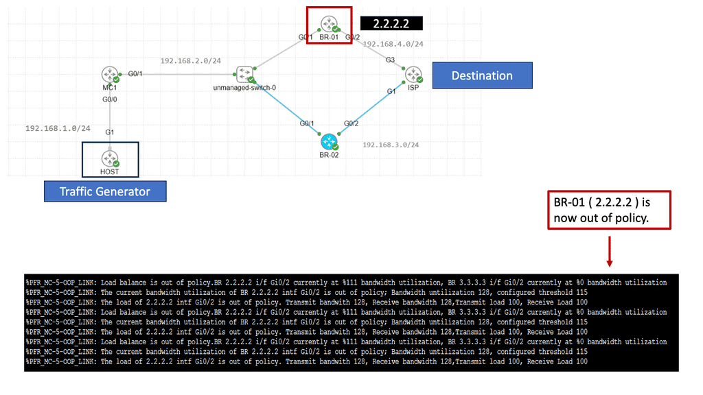
Performance-Based Routing

Understanding Performance Routing

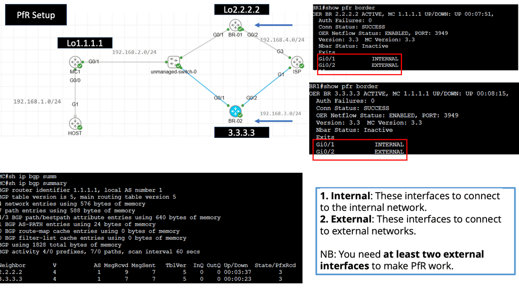
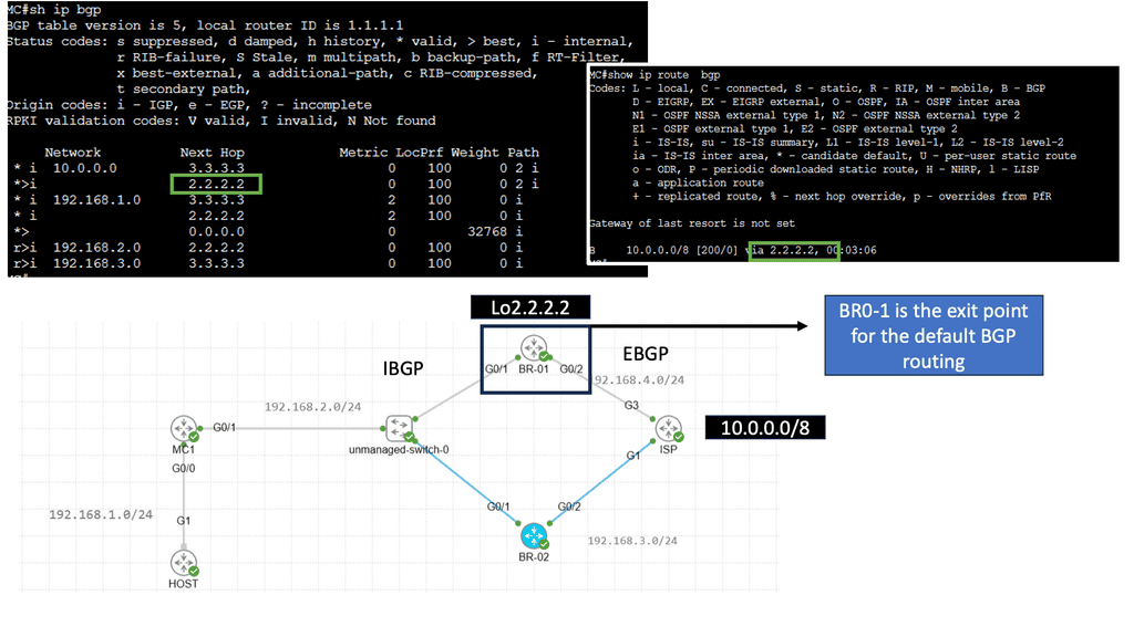
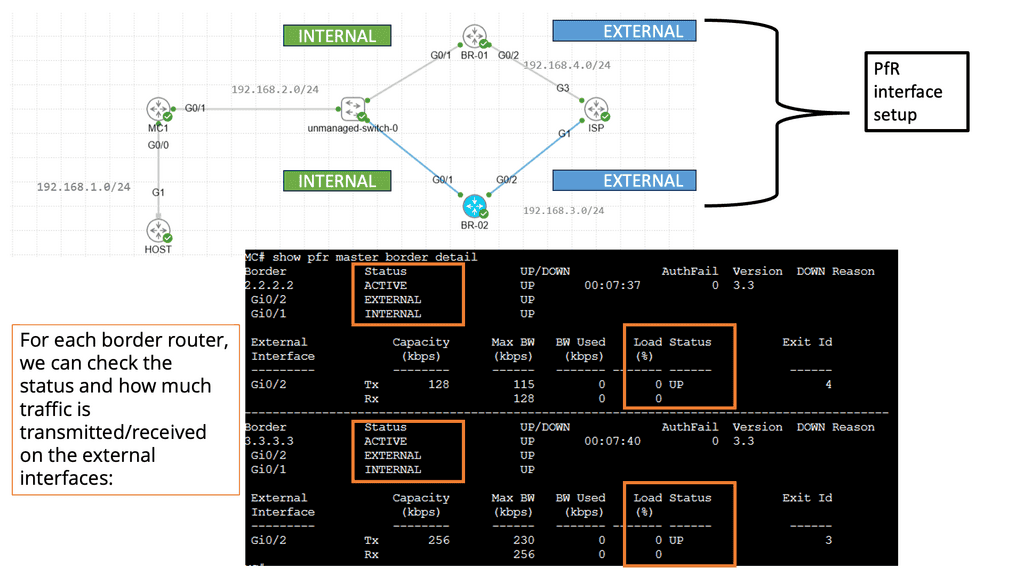
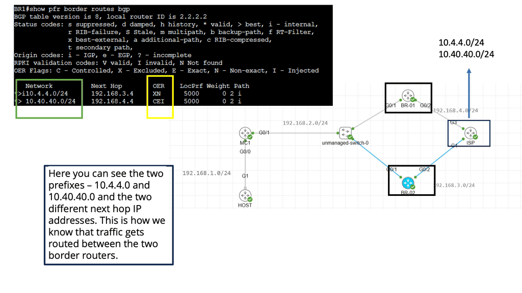
Performance Routing, or PfR, is an intelligent routing mechanism that optimizes network traffic based on real-time conditions. Unlike traditional routing protocols, PfR goes beyond static routing tables and dynamically selects the best path for data packets to reach their destination. This dynamic decision-making is based on congestion, latency, and link quality, ensuring an optimal end-user experience

PfR operates by continuously monitoring network performance metrics such as delay, jitter, and packet loss. It collects this data from various sources, including network probes and flow-based measurements. Using this information, PfR dynamically calculates the best path for each data flow, considering factors like available bandwidth and desired Quality of Service (QoS). This intelligent decision-making process happens in real time, adapting to changing network conditions.

Related: You may find the following posts helpful for pre-information:

  1. Transport SDN
  2. Network Visibility
  3. Load Balancing
  4. Chaos Engineering Kubernetes
  5. Segment Routing
  6. What is OpenFlow
  7. DMVPN Phases

Network Traffic Engineering

Importance of Network Traffic Engineering

Guide: MPLS Forwarding

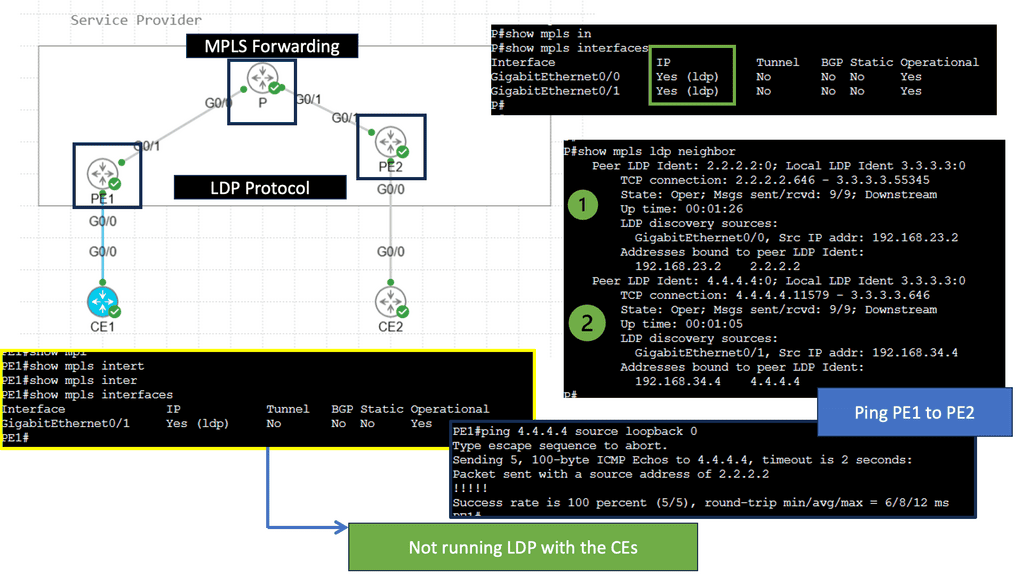
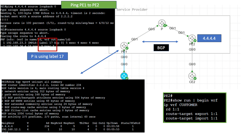
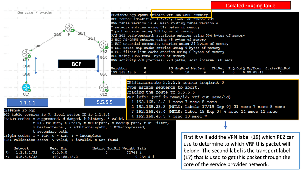
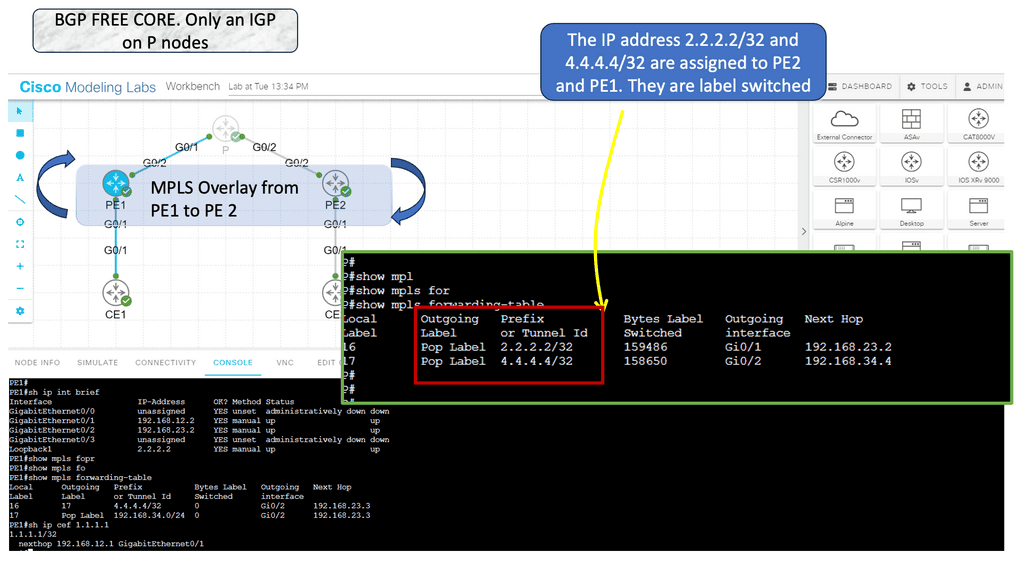
In the following guide, we have an MPLS network. MPLS networks have devices with different roles. So, we have the core node called the “P” provider and the “PE” provider edge nodes. The beauty of MPLS forwarding is that we can have scale in the network’s core. The P nodes do not need customer routes from the CE devices. These are usually carried out in BGP.

Note:

However, with an MPLS network, we have MPLS forwarding between the loopbacks. Notice the diagram below. The loopback addresses 2.2.2.2/32 and 4.4.4.4/32 belong to the PE nodes. The P node is entirely unaware of any BGP routing.

MPLS overlay
Diagram: MPLS Overlay

Knowledge Check: IntServ and RSVP

Quality of Service (QoS) can be measured in three ways:

  • Best Effort (don’t use QoS for traffic that doesn’t need special treatment.)

  • DiffServ (Differentiated Services)

  • IntServ (Integrated Services)

DiffServ implements QoS by classifying IP packets based on their ToS byte or hop by hop. INTSERV is entirely different; it’s a signaling process where network flows can request a specific bandwidth and delay. RFC 1633 describes two components of IntServ:

  • Resource reservation

  • Admission control

Reserved resources notify the network that a certain amount of bandwidth and delay is needed for a particular flow. When the reservation is successful, a network component (primarily routers) reserves bandwidth and delay. Reservations are permitted or denied by admission control. We cannot guarantee any service without allowing all flows to make reservations.

RSVP path messages are used when a host requests a reservation. This message is passed along the route on the way to the destination. A router will forward a message when it can guarantee the bandwidth/delay required.

An RSVP resv message will be sent once it reaches the destination. In the opposite direction, the same process will occur. Upon receiving the reservation message from the host, each router will check if it has enough bandwidth/delay for the flow and forward it to the source of the reservation.

While this might sound nice, IntServ is challenging to scale…each router must keep track of each reservation for each flow. Is there a problem if a particular router does not support Intserv or its reservation information is lost? We primarily use RSVP for MPLS traffic engineering and DiffServ for QoS implementations.

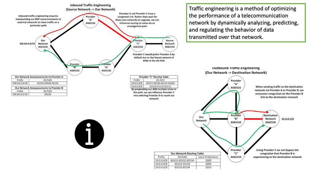
Traffic Engineering: Inbound and Outbound

Before you can understand how to use MPLS to do traffic engineering, you must understand what traffic engineering is. So, we have network engineering that manipulates your network to suit your traffic. You make the most reasonable predictions about how traffic will flow across your network and then order the right components.

Then we have traffic engineering. Network traffic engineering is manipulating traffic to fit your network. Traffic engineering is not MPLS-specific but a general practice among all networking and security technologies. It could be a simple or complex implementation. Something as simple as tweaking IP metrics on the interface can be implemented in its simplest form for traffic engineering. Then, we have traffic engineering specific to MPLS.

Network traffic engineering
Diagram: Network Traffic Engineering. Source AWS

Guide: MPLS TE

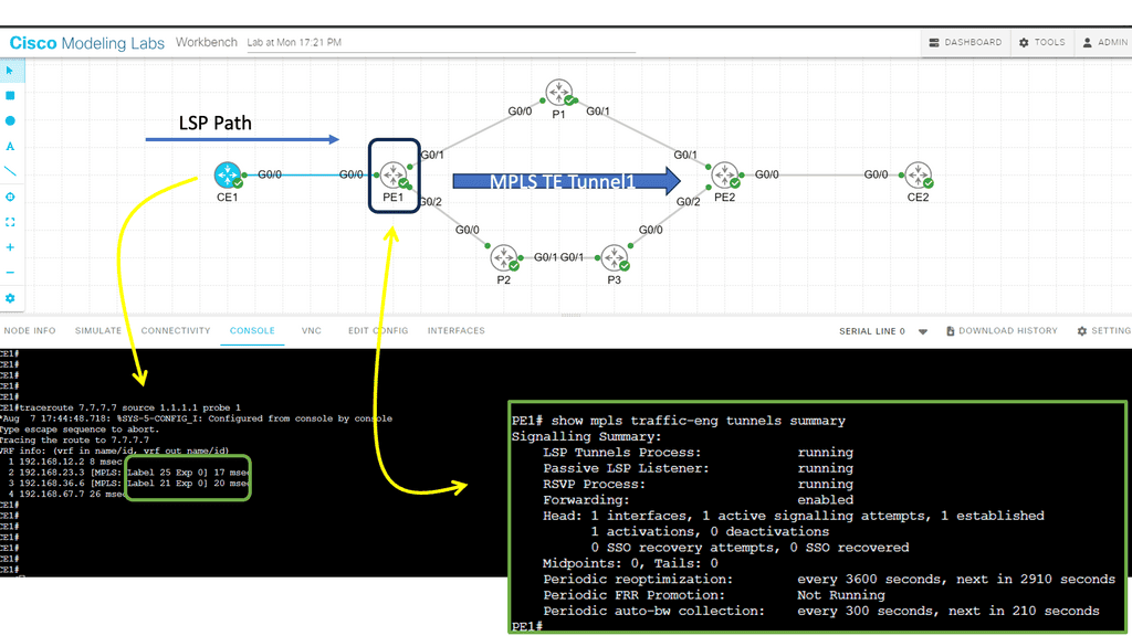
In this lab, we will examine MPLS TE with ISIS configuration. Our MPLS core network consists of PE1, P1, P2, P3, and PE2 routers. The CE1 and CE2 routers use regular IP routing. All routers are configured to use IS-IS L2. 

Tip: There are four main items we have to configure:

  • Enable MPLS TE support:
    • Globally
    • Interfaces
  • Configure IS-IS to support MPLS TE.
  • Configure RSVP.
  • Configure a tunnel interface.
MPLS TE
Diagram: MPLS TE

Understanding MPLS and MPLS forwarding

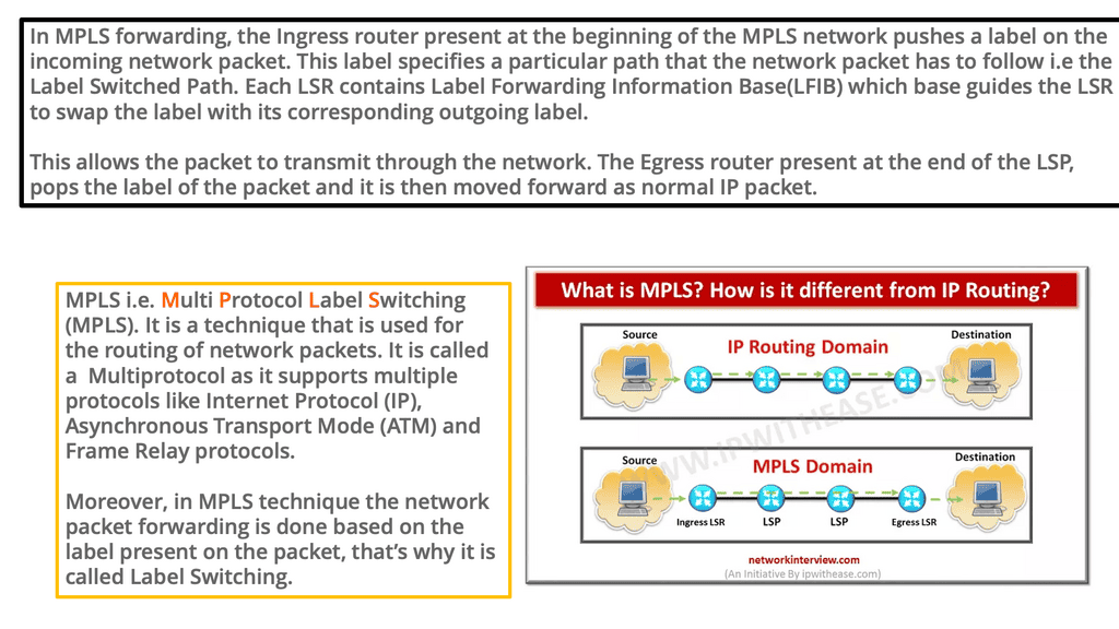
– MPLS is the de facto technology for service provider WAN networks. Its scalable architecture moves complexity and decision-making to the network’s edges, leaving the core to label switch packets efficiently. The PE nodes sit at the edge and perform path calculations and encapsulations. The P nodes sit in the core and label switch packets. They only perform MPLS switching and have no visibility of customer routes.

– Edge MPLS routers map incoming packets into forwarding equivalence classes (FEC) and use a different label-switched path (LSP) for each forwarding class. Keeping the network core simple enables scalable network designs. Many of today’s control planes encompass a distributed architecture and can make forwarding decisions independently.

– MPLS control plane still needs a distributed IGP (OSPF and ISIS) to run in the core and a distributed label allocation protocol (LDP) to label packets. Still, it shifted how we think of control planes and distributed architectures. MPLS reduced the challenges of some early control plane approaches but proposes challenges by not having central visibility, especially for traffic engineering (TE).

MPLS forwarding
Diagram: MPLS Forwarding. The source is NetworkInterview.

Example Technology: DMVPN Phase 3 Traffic Manipulation

DMVPN Phase 3 is the third and final phase of a Dynamic Multipoint Virtual Private Network DMVPN setup. This phase is focused on implementing the DMVPN tunnel and enabling dynamic routing. The tunnel is built between multiple network points, allowing communication between them.

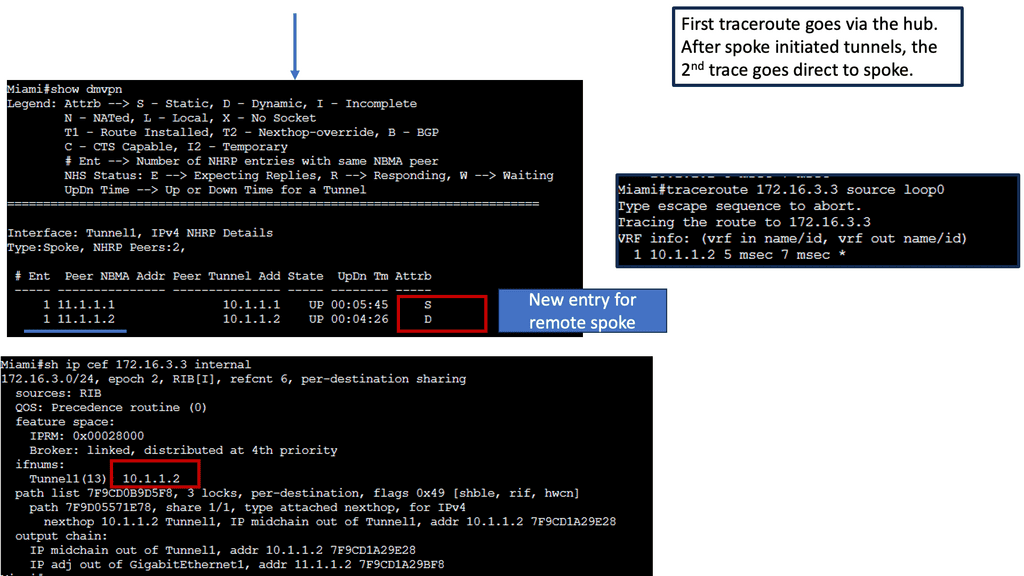
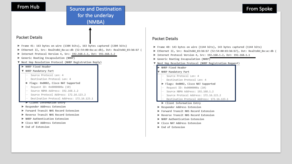
In DMVPN Phase 1, the spoke devices rely on the configured tunnel destination to identify where to send the encapsulated packets. Phase 3 DMVPN uses mGRE tunnels and depends on NHRP redirect and resolution request messages to determine the NBMA addresses for destination networks.

Packets flow through the hub in a traditional hub-and-spoke manner until the spoke-to-spoke tunnel has been established in both directions. Then, as packets flow across the hub, the hub engages NHRP redirection to find a more optimal path with spoke-to-spoke tunnels.

NHRP Routing Table Manipulation

NHRP tightly interacts with the routing/forwarding tables and installs or modifies routes in the Routing Information Base (RIB), also known as the routing table, as necessary. If an entry exists with an exact match for the network and prefix length, NHRP overrides the existing next hop with a shortcut. The original protocol is still responsible for the prefix, but the percent sign (%) indicates overwritten next-hop addresses in the routing table.

DMVPN Phase 3
Diagram: DMVPN Phase 3 configuration

Guide: DMVPN Phase 3

The following example shows DMVPN Phase 3 running on the network.

DMVPN Phase 3 is the latest iteration of the DMVPN technology, offering enhanced scalability and flexibility compared to its predecessors. It builds upon the foundation of Phase 1 and Phase 2, incorporating improvements that address the limitations of these earlier versions.

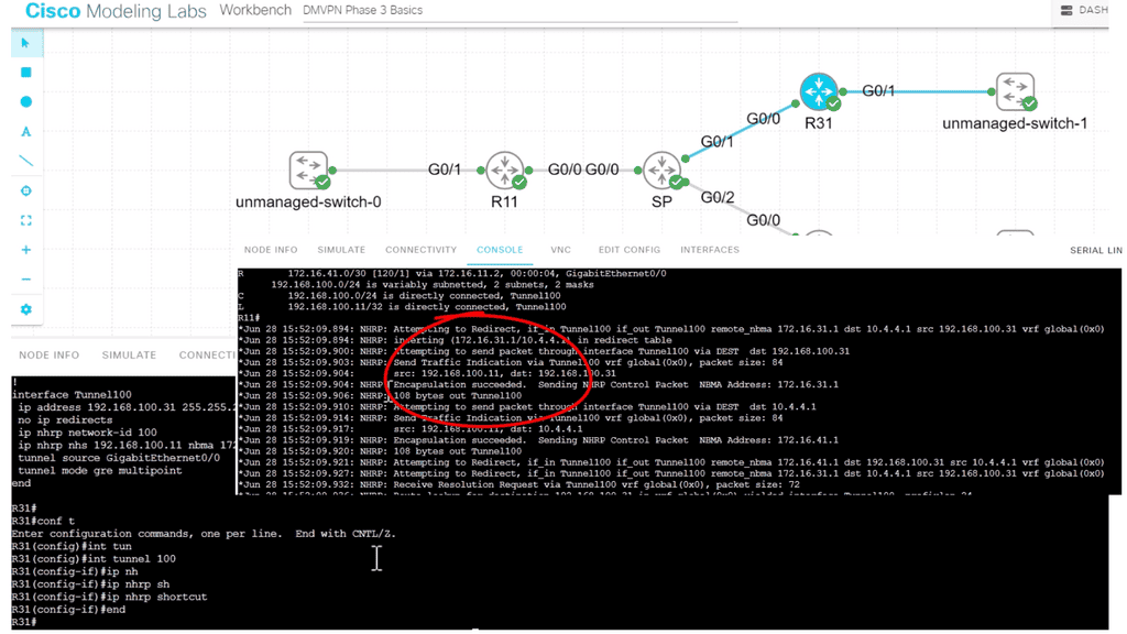
One of the critical features of DMVPN Phase 3 is the addition of a hub-and-spoke network topology. This allows for a centralized hub connecting multiple remote spokes, creating a dynamic and efficient network infrastructure. The hub is a central point for all spokes, enabling secure communication. In our case below, R11 is the hub, and R31 and R41 are the spokes.

Note:

Once the hub site receives traffic indicating spoke to spoke traffic, it sends back a “Traffic Indication” message. Notice the output from the debug command below. Via NHRP, the spoke knows a better path to reach the other spoke, not via the hub. The spoke then proceeds to build spoke-to-spoke tunnels.

DMVPN Phase 3
Diagram: DMVPN Phase 3 configuration

Network Traffic Engineering and MPLS 

MPLS was very successful, and significant service provider networks could support many customers by employing MPLS-style architecture. End-to-end Label Switch Paths (LSP) are extended to interconnect multiple MPLS service providers, route reflectors, and BGP confederations for large-scale deployments and complexity reduction.

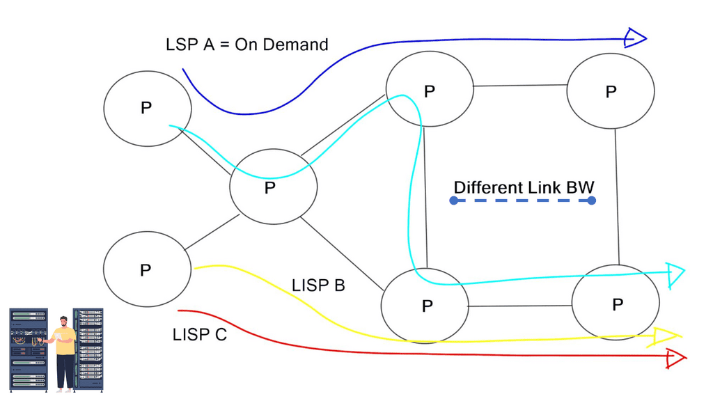
However, no matter how scalable the MPLS architecture could be, you can’t escape the fact that Inter-DC circuit upgrades are time-consuming and expensive. To help alleviate this, MPLS providers introduced MPLS Traffic engineering (TE). TE moves traffic to other parts of the network to underutilized sections.

While simple TE can be done with IGP metrics, they don’t satisfy unique traffic class requirements. Therefore, provider networks commonly deploy MPLS RSVP/ TE. This type of TE enhances IGP metric tuning, allowing engineers to forward core traffic over non-shortest paths. The non-shorted path is used to avoid network “hot spots.” Since the traffic is now moved to other underutilized network parts, it prevents the lengthy process of upgrading congested core links. MPLS TE distributes traffic optimally across a network. “MPLS RSVP/ TE is a widely adopted and well-defined technology. Can SDN and OpenFlow do a better job?”

Network Traffic Engineering
Diagram: Network traffic engineering.

Holistic visibility – Controller-based networking

MPLS/TE is a distributed architecture. There is no real-time global view of the end-to-end network path. The lack of a global view may induce incorrect traffic engineering decisions, lack of predictability, and deterministic scheduling of LSPs.

Some tools work with MPLS TE to create a holistic view, but they are usually expensive and do not offer a “real-time” picture. They often make an offline topology. They also don’t change the fact that MPLS is a distributed architecture.

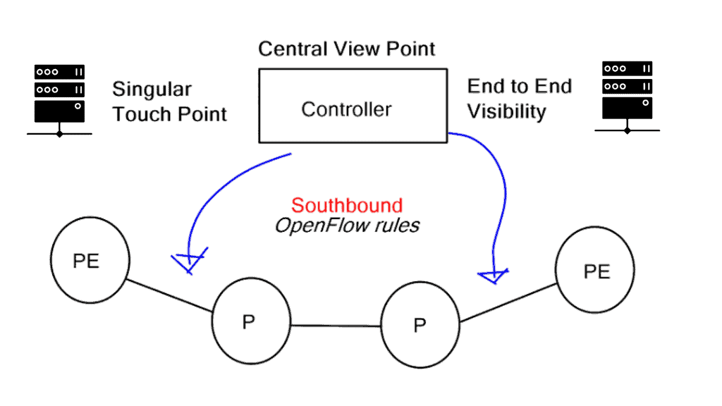
The significant advantage of a centralized SDN and OpenFlow framework, commonly called MPLS OpenFlow, is that you have a holistic view of the network, controller-based networking. The centralized software sits on the controllers, analyzing and controlling the production network forwarding paths. It has a real-time network view and gains insights into various network analytics about link congestion, delay, latency, drops, and other performance metrics.
mpls openflow
Diagram: MPLS OpenFlow

MPLS OpenFlow can push down rules to the nodes per-flow basis, offering a granular approach to TE. The traditional TE mechanism is challenging in achieving a per-flow TE state. OpenFlow’s finer granularity is also evident in service insertion use casesIn addition, OpenFlow 1.4 supports better statistics that give you visibility into application performance.

This metric and a central viewpoint can only enhance traffic engineering decisions. Let’s face it: MPLS RSVP/TE, while widely deployed, involves several control plane protocols. All these protocols need to interact and work together.

The OpenFlow MPLS protocol steers traffic over MPLS using OpenFlow.

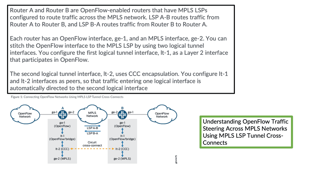
You can direct traffic from OpenFlow networks over MPLS LSP tunnel cross-connects and logical tunnel interfaces. By stitching OpenFlow interfaces to MPLS label-switched paths (LSPs), you can direct OpenFlow traffic onto MPLS networks. In addition, through MPLS LSP tunnel cross-connects between interfaces and LSPs, you can connect the OpenFlow network to a remote network by creating MPLS tunnels that use LSPs as conduits.

MPLS OpenFlow
Diagram: MPLS OpenFlow. The source is Juniper.

Network state vs. Centralized end-to-end visibility

RSVP requires that some state is stored on the Label Switch Router (LSR). The state is always bad for a network and imposes control plane scalability concerns. The network state is also a target for attack. Hierarchical RSVP was established to combat the state problem, but in my opinion, it adds to network complexity. All these kludges become an operational nightmare and require skilled staff to design, implement, and troubleshoot.

Removing MPLS signaling protocols from the network and the state they need to maintain eliminates some of the scale concerns with MPLS TE. Distributed control planes must maintain many tables and neighbor relationships (LSDB and TED). They all add to network complexity.

Predictable and deterministic TE solution

Using SDN and OpenFlow for traffic engineering provides a more predictable and deterministic TE solution. By informing the OpenFlow controller that you want the traffic redirected toward a specific MAC address, the necessary forwarding entries are programmed and automatically appear across the path. NETCONF and MPLS-TP are possibilities, but they operationally cause problems and don’t alleviate the distributed signaling protocols.

Having a central controller view, the contents of the network allow for particular network touchpoints. New features are implemented in the software and pushed down to the individual nodes. Similar to all SDN architectures, fewer network touchpoints increase network agility. The box-by-box and manual culture is slowly disappearing.

Challenges and Future Trends

Network traffic engineering faces several challenges, including ever-increasing data volumes, evolving network architectures, and the rise of new technologies such as cloud computing and the Internet of Things (IoT). However, emerging trends like Software-Defined Networking (SDN) and Artificial Intelligence (AI) are promising to address these challenges and optimize network traffic.

Closing Points on Network Traffic Engineering

Network traffic engineering is the process of optimizing the flow of data packets across a network. It involves analyzing and managing network traffic to ensure that data travels along the most efficient paths, minimizing latency and preventing congestion. By strategically directing data, network administrators can improve the overall performance and reliability of the network.

Various techniques and tools are employed in network traffic engineering to achieve optimal network performance. Techniques such as load balancing, Quality of Service (QoS), and Multiprotocol Label Switching (MPLS) are commonly used to distribute traffic evenly and prioritize critical data. Additionally, modern tools like traffic analyzers and network simulators help administrators visualize and manage network traffic effectively.

Despite its benefits, network traffic engineering presents several challenges. Networks are constantly evolving, with increasing data volumes and complex architectures. Administrators must continuously adapt their strategies to cope with these changes, ensuring optimal performance. Additionally, security concerns must be addressed, as misconfigured traffic routes can expose the network to potential vulnerabilities.

The future of network traffic engineering is promising, with advancements in artificial intelligence and machine learning poised to revolutionize the field. These technologies can automate traffic management, predict congestion points, and suggest optimal routing paths, making networks more intelligent and responsive to dynamic conditions.


Summary: Network Traffic Engineering

Understanding Network Traffic Engineering

Network traffic engineering analyzes and manipulates traffic to enhance performance and meet specific objectives. It involves various techniques such as traffic shaping, route optimization, and load balancing. By intelligently managing the flow of data packets, network administrators can ensure optimal utilization of available bandwidth and minimize latency issues.

Traffic Engineering Techniques

Traffic Shaping

Traffic shaping is a technique used to control network traffic flow by enforcing predetermined bandwidth limits. It allows administrators to prioritize critical applications or services, ensuring smooth operation during peak traffic hours. By regulating the rate at which data packets are transmitted, traffic shaping helps prevent congestion and maintain a consistent user experience.

Route Optimization

Route optimization focuses on selecting the most efficient paths for data packets to travel across a network. Network engineers can determine the optimal routes that minimize delays and packet loss by analyzing various factors such as latency, bandwidth availability, and network topology. This ensures faster data transmission and improved overall network performance.

Load Balancing

Load balancing is a technique that distributes network traffic across multiple paths or devices, avoiding bottlenecks and optimizing resource utilization. By evenly distributing the workload, load balancers ensure that no single component is overwhelmed with traffic, thereby improving network efficiency and preventing congestion.

Benefits of Network Traffic Engineering

Enhanced Performance

By implementing traffic engineering techniques, network administrators can significantly enhance network performance. Reduced latency, improved throughput, and minimized packet loss contribute to a smoother and more efficient network operation.

Scalability and Flexibility

Network traffic engineering enables scalability and flexibility in network design. It allows for the efficient allocation of resources and the ability to adapt to changing traffic patterns and demands. This ensures that networks can handle increasing traffic volumes without sacrificing performance or user experience.

Effective Resource Utilization

Optimized network traffic engineering ensures that network resources are utilized effectively, maximizing the return on investment. By efficiently managing bandwidth and routing paths, organizations can avoid unnecessary expenses on additional infrastructure and improve overall cost-effectiveness.

Challenges and Considerations

While network traffic engineering offers numerous benefits, it also comes with its own set of challenges. Factors such as dynamic traffic patterns, evolving network technologies, and security considerations must be considered. Network administrators must stay updated with industry trends and continuously monitor and analyze network performance to address these challenges effectively.

Conclusion: Network traffic engineering is a critical discipline that ensures computer networks’ efficient and reliable functioning. By employing various techniques and protocols, network administrators can optimize resource utilization, enhance the quality of service, and pave the way for future network scalability. As technology evolves, staying updated with emerging trends and best practices in network traffic engineering will be crucial for organizations to maintain a competitive edge in today’s digital landscape.