Optimal Layer 3 Forwarding
Layer 3 forwarding is crucial in ensuring efficient and seamless network data transmission. Optimal Layer 3 forwarding, in particular, is an essential aspect of network architecture that enables the efficient routing of data packets across networks. In this blog post, we will explore the significance of optimal Layer 3 forwarding and its impact on network performance and reliability.
Layer 3 forwarding directs network traffic based on its network layer (IP) address. It operates at the network layer of the OSI model, making it responsible for routing data packets across different networks. Layer 3 forwarding involves analyzing the destination IP address of incoming packets and selecting the most appropriate path for their delivery.
Enhanced Network Performance: Optimal layer 3 forwarding optimizes routing decisions, resulting in faster and more efficient data transmission. It eliminates unnecessary hops and minimizes packet loss, leading to improved network performance and reduced latency.
Scalability: With the exponential growth of network traffic, scalability becomes crucial. Optimal layer 3 forwarding enables networks to handle increasing traffic demands by efficiently distributing packets across multiple paths. This scalability ensures that networks can accommodate growing data loads without compromising on performance.
Load Balancing: Layer 3 forwarding allows for intelligent load balancing by distributing traffic evenly across available network paths. This ensures that no single path becomes overwhelmed with traffic, preventing bottlenecks and optimizing resource utilization.
Implementing Optimal Layer 3 Forwarding
Hardware and Software Considerations: Implementing optimal layer 3 forwarding requires suitable network hardware and software support. It is essential to choose routers and switches that are capable of handling the increased forwarding demands and provide advanced routing protocols.
Configuring Routing Protocols: To achieve optimal layer 3 forwarding, configuring robust routing protocols is crucial. Protocols such as OSPF (Open Shortest Path First) and BGP (Border Gateway Protocol) play a significant role in determining the best path for packet forwarding. Fine-tuning these protocols based on network requirements can greatly enhance overall network performance.
Real-World Use Cases
Data Centers:In data center environments, optimal layer 3 forwarding is essential for seamless communication between servers and networks. It enables efficient load balancing, fault tolerance, and traffic engineering, ensuring high availability and reliable data transfer.
Wide Area Networks (WAN):For organizations with geographically dispersed locations, WANs are the backbone of their communication infrastructure. Optimal layer 3 forwarding in WANs ensures efficient routing of traffic across different locations, minimizing latency and maximizing throughput.Matt Conran
Highlights: Optimal Layer 3 Forwarding
What is Routing?
Routing is like a network’s GPS. It involves directing data packets from their source to their destination across multiple networks. Think of it as the process of determining the best possible path for data to travel. Routers, the key devices responsible for routing, use various algorithms and protocols to make intelligent decisions about where to send data packets next.
The Role of Switching
While routing deals with data flow between networks, switching comes into play within a single network. Switches serve as the traffic managers within a local area network (LAN). They connect devices, such as computers, printers, and servers, allowing them to communicate with one another. Switches receive incoming data packets and use MAC addresses to determine which device the data should be forwarded to. This efficient and direct communication within a network makes switching so critical.
The Role of Optimal Layer 3 Forwarding:
Optimal Layer 3 forwarding ensures that data packets are transmitted through the most efficient path, improving network performance. It minimizes packet loss, latency, and jitter, enhancing user experience. By selecting the best path, optimal Layer 3 forwarding also enables load balancing, distributing the traffic evenly across multiple links, thus preventing congestion.
Implementation of Layer 3 Forwarding
Routing protocols: Layer 3 forwarding relies on routing protocols such as OSPF (Open Shortest Path First) and BGP (Border Gateway Protocol) to exchange routing information and build forwarding tables. These protocols use various algorithms and metrics to determine the best paths for packet forwarding.
Quality of Service (QoS): Layer 3 forwarding can be enhanced with QoS mechanisms to prioritize certain types of traffic. Assigning different priority levels ensures critical data, such as real-time voice or video, receives preferential treatment, resulting in improved user experience.
Challenges and Considerations
Security: Layer 3 forwarding introduces potential security risks involving routing packets across different networks. Implementing robust security measures, such as access control lists (ACLs) and firewall policies, is essential to protect against unauthorized access and network attacks.
Network congestion: In complex network environments, layer 3 forwarding can lead to congestion if not correctly managed. Network administrators must carefully monitor and analyze traffic patterns to proactively address congestion issues and optimize routing decisions.
Example: Arista with Large Layer-3 Multipath
Arista EOS supports hardware for Leaf ( ToR ), Spine, and Spline data center design layers. Its wide product range supports significant layer-3 multipath ( 16 – 64-way ECMP ) with excellent optimal Layer 3-forwarding technologies. Unfortunately, multi-protocol Label Switching ( MPLS ) is limited to static MPLS labels, which could become an operational nightmare. As of yet, no Fibre Channel over Ethernet ( FCoE ) support exists.
Arista supports massive Layer-2 Multipath with ( Multichassis Link aggregation ) MLAG. Validated designs with Arista Core 7508 switches ( offer 768 10GE ports ) and Arista Leaf 7050S-64 support over 1980 x 10GE server ports with 1:2,75 oversubscription. That’s a lot of 10GE ports. Do you think layer 2 domains should be designed to that scale?
Related: Before you proceed, you may find the following helpful:
Optimal Layer 3 Forwarding Key Optimal Layer 3 Forwarding Discussion Points: |
|
Back to Basics: Router operation and IP forwarding
Every IP host in a network is configured with its IP address and mask and the IP address of the default gateway. Suppose the host wants to send traffic, which, in our case, is to a destination address that does not belong to a subnet to which the host is directly attached; the host passes the packet to the default gateway. For example, the default gateway would be a Layer 3 router.
The Role of The Default Gateway
A standard misconception is how the address of the default gateway is used. People mistakenly believe that when a packet is sent to the Layer 3 default router, the sending host sets the destination address in the IP packet as the default gateway router address. However, if this were the case, the router would consider the packet addressed to itself and not forward it any further. So why configure the default gateway’s IP address?
First, the host uses the Address Resolution Protocol (ARP) to find the specified router’s Media Access Control (MAC) address. Then, having acquired the router’s MAC address, the host sends the packets directly to it as data link unicast submissions.
Benefits of Optimal Layer 3 Forwarding:
1. Enhanced Scalability: Optimal Layer 3 forwarding allows networks to scale effectively by efficiently handling a growing number of connected devices and increasing traffic volumes. It enables seamless expansion without compromising network performance.
2. Improved Network Resilience: By selecting the most efficient path for data packets, optimal Layer 3 forwarding enhances network resilience. It enables networks to quickly adapt to network topology or link failure changes, rerouting traffic to ensure uninterrupted connectivity.
3. Better Resource Utilization: Optimal Layer 3 forwarding optimizes resource utilization by distributing traffic across multiple links. This enables efficient utilization of available network capacity, reducing the risk of bottlenecks and maximizing the network’s throughput.
4. Enhanced Security: Optimal Layer 3 forwarding contributes to network security by ensuring traffic is directed through secure paths. It also enables the implementation of firewall policies and access control lists, protecting the network from unauthorized access and potential security threats.
Implementing Optimal Layer 3 Forwarding:
To achieve optimal Layer 3 forwarding, various technologies and protocols are utilized, such as:
1. Routing Protocols: Dynamic routing protocols, such as OSPF (Open Shortest Path First) and BGP (Border Gateway Protocol), enable networks to exchange routing information automatically and determine the best path for data packets.
2. Quality of Service (QoS): QoS mechanisms prioritize network traffic, ensuring that critical applications receive the necessary bandwidth and reducing the impact of congestion.
3. Network Monitoring and Analysis: Continuous network monitoring and analysis tools provide real-time visibility into network performance, enabling administrators to identify and resolve potential issues promptly.
Arista deep buffers: Why are they important?
A vital switch table you need to be concerned with for large 3 networks is the size of Address Resolution Protocol ( ARP ) tables. When ARP tables become full and packets are offered with the destination ( next hop ) that isn’t cached, the network will experience flooding and suffer performance problems.
Arista Spine switches have deep buffers, ideal for bursty and latency-sensitive environments. They are also perfect when you have little knowledge of the application traffic matrix, as they can handle most types efficiently.
Finally, deep buffers are most useful in spine layers as traffic concentration occurs in these layers. If you are concerned that ToR switches do not have enough buffers, physically direct servers to chassis-based switches in the Core / Spine layer.
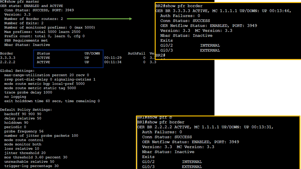
Knowledge Check: Cisco PfR
Understanding Cisco PfR
Cisco PfR, also known as Cisco Performance Routing, is an intelligent network optimization technology that dynamically manages traffic flows to ensure optimal performance. It combines sophisticated algorithms, real-time monitoring, and path selection to intelligently route network traffic, leveraging multiple paths and network resources.
The Benefits of Cisco PfR
Enhanced Network Resilience and Redundancy
By continuously monitoring network conditions and dynamically adapting to changes, Cisco PfR ensures network resilience. It automatically reroutes traffic when network congestion, link failures, or other performance issues occur, minimizing downtime and disruptions.
Improved Application Performance
With Cisco PfR, network traffic is intelligently distributed across multiple paths based on application requirements. This optimization ensures critical applications receive the necessary bandwidth and low latency, enhancing the overall user experience.
Cost-Efficient Bandwidth Utilization
By intelligently distributing traffic across available network resources, Cisco PfR optimizes bandwidth utilization. It can dynamically choose the path with the lowest cost or least congestion, resulting in significant cost savings for organizations.
Optimal layer 3 forwarding
Every data center has some mix of layer 2 bridging and layer 3 forwardings. The design selected depends on layer 2 / layer 3 boundaries. Data centers that use MAC-over-IP usually have layer 3 boundaries on the ToR switch. While fully virtualized data centers require large layer two domains ( for VM mobility ); VLANs span Core or Spine layers.
Either of these designs can result in suboptimal traffic flow. Layer 2 forwarding in ToR switches and layer 3 forwarding in Core may result in servers in different VLANs connected to the same ToR switches being hairpinned to the closest Layer 3 switch.
Solutions that offer optimal Layer 3 forwarding in the data center were available. These may include stacking ToR switches, architectures that present the whole fabric as a single layer 3 elements ( Juniper QFabric ), and controller-based architectures (NEC’s Programmable Flow ). While these solutions may suffice for some business requirements, they don’t have optimal Layer 3 forward across the whole data center while using sets of independent devices.
Arista Virtual ARP does this. All ToR switches share the same IP and MAC with a common VLAN. Configuration involves the same first-hop gateway IP address on a VLAN for all ToR switches and mapping the MAC address to the configured shared IP address. The design ensures optimal Layer 3 forwarding between two ToR endpoints and optimal inbound traffic forwarding.

Load balancing enhancements
Arista 7150 is an ultra-low latency 10GE switch ( 350 – 380 ns ). It offers load-balancing enhancements other than the standard 5-tuple mechanism. Arista supports new load-balancing profiles. Load-balancing profiles allow you to decide what bit and byte of the packet you want to use as the hash for the load-balancing mechanism—offering more scope and granularity than the traditional 5-tuple mechanism.
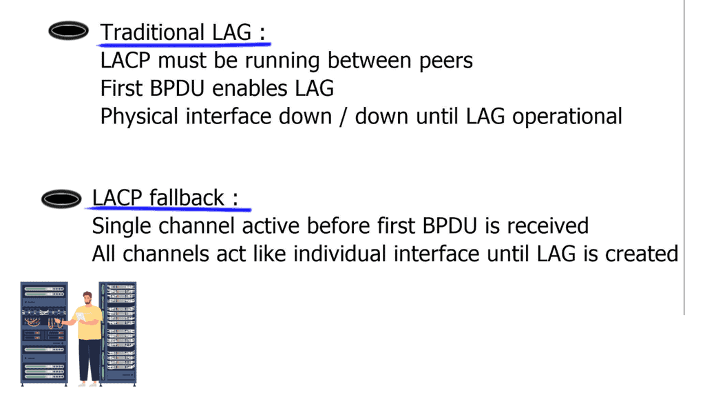
LACP fallback
With traditional Link Aggregation ( LAG ), LAG is enabled after receiving the first LACP packet. This is because the physical interfaces are not operational and are down / down before receiving LACP packets. This is viable and perfectly OK unless you need auto-provisioning. What does LACP fallback mean?
If you don’t receive an LACP packet and the LACP fallback is configured, one of the links will still become active and will be UP / UP. Continue to use the Bridge Protocol Data Unit ( BPDU ) guard on those ports, as you don’t want a switch to bridge between two ports, so create a forwarding loop.
Direct server return
7050 series supports Direct Server Return. The load balancer in the forwarding path does not do NAT. Implementation includes configuring VIP on the load balancer’s outside IP and the internal servers’ loopback. It is essential not to configure the same IP address on server LAN interfaces, as ARP replies will clash. The load balancer sends the packet unmodified to the server, and the server sends it straight to the client.
Requires layer 2 between the load balancer and servers; load balancer needs to use MAC address between the load balancer and servers. It is possible to use IP called Direct Server Return IP-in-IP. Requires any layer 3 connectivity between the load balancer and servers.
Arista 7050 IP-in-IP Tunnel supports essential load balancing, so one can save the cost of not buying an external load-balancing device. However, it’s a scaled-down model, and you don’t get the advanced features you might have with Citrix or F5 load balancers.
Link flap detection
Networks have a variety of link flaps. Networks can experience fast and regular flapping; sometimes, you get irregular flapping. Arista has a generic mechanism to detect flaps so you can create flap profiles that offer more granularity to flap management. Flap profiles can be configured on individual interfaces or globally. It is possible to have multiple profiles on one interface.
Detecting failed servers
The problem is when we have scale-out applications, and you need to detect server failures. When no load balancer appliance exists, this has to be with application-level keepalives or, even worse, Transmission Control Protocol ( TCP ) timeouts. TCP timeout could take minutes. Arista uses Rapid Indication of Link Loss ( RAIL ) to improve performance. RAIL improves the convergence time of TCP-based scale-out applications.
OpenFlow support
- Support OpenFlow Protocol 1.0. Available on 7050 series.
Arista matches 750 complete entries or 1500 layer 2 match entries, which would be destination MAC addresses. They can’t match IPv6 or any ARP codes or inside ARP packets, which are part of OpenFlow 1.0. Limited support enables only VLAN or layer 3 forwardings. If matching on layer 3 forwarding, match either the source or destination IP address and rewrite the layer 2 destination address to the next hop.
Arista offers a VLAN bind mode, configuring a certain amount of VLANs belonging to OpenFlow and another set of VLANs belonging to standard Layer 3. Openflow implementation is known as “ships in the night.”
Arista also supports a monitor mode. Monitor mode is regular forwarding with OpenFlow on top of it. Instead of allowing the OpenFlow controller to forward forwarding entries, forwarding entries are programmed by traditional means via Layer 2 or Layer 3 routing protocol mechanism. OpenFlow processing is used parallel to conventional routing—openflow then copies packets to SPAN ports, offering granular monitoring capabilities.
DirectFlow
Direct Flow – I want all traffic from source A to destination A to go through the standard path, but any HTTP traffic goes via a firewall for inspection. i.e., set the output interface to X and a similar entry for the return path, and now you have traffic going to the firewall but for port 80 only.
It offers the same functionality as OpenFlow but without a central controller piece. DirectFlow can configure OpenFlow with forwarding entries through CLI or REST API and is used for Traffic Engineering ( TE ) or symmetrical ECMP. Direct Flow is easy to implement as you don’t need a controller. Just use a REST API available in EOS to configure the flows.
Optimal Layer 3 Forwarding: Final Points
Optimal Layer 3 forwarding is a critical network architecture component that significantly impacts network performance, scalability, and reliability. Efficiently routing data packets through the best paths enhances network resilience, resource utilization, and security.
Implementing optimal Layer 3 forwarding through routing protocols, QoS mechanisms, and network monitoring ensures a robust and efficient network infrastructure. Embracing this technology allows organizations to deliver seamless connectivity and a superior user experience in today’s increasingly interconnected world.
Summary: Optimal Layer 3 Forwarding
In today’s rapidly evolving networking world, achieving efficient, high-performance routing is paramount. Layer 3 forwarding is crucial in this process, enabling seamless communication between different networks. This blog post delved into optimal layer 3 forwarding, exploring its significance, benefits, and implementation strategies.
Section 1: Understanding Layer 3 Forwarding
Layer 3 forwarding, also known as IP forwarding, is the process of forwarding network packets at the network layer of the OSI model. It involves making intelligent routing decisions based on IP addresses, enabling data to travel across different networks efficiently. By understanding the fundamentals of layer 3 forwarding, we can unlock its full potential.
The Significance of Optimal Layer 3 Forwarding
Optimal layer 3 forwarding is crucial in modern networking architectures. It ensures packets are forwarded through the most efficient path, minimizing latency and maximizing throughput. With exponential data traffic growth, optimizing layer 3 forwarding becomes essential to support demanding applications and services.
Strategies for Achieving Optimal Layer 3 Forwarding
There are several strategies and techniques that network administrators can employ to achieve optimal layer 3 forwarding. These include:
1. Load Balancing: Distributing traffic across multiple paths to prevent congestion and utilize available network resources efficiently.
2. Quality of Service (QoS): Implementing QoS mechanisms to prioritize certain types of traffic, ensuring critical applications receive the necessary bandwidth and low latency.
3. Route Optimization: Utilizing advanced routing protocols and algorithms to select the most efficient paths based on real-time network conditions.
4. Network Monitoring and Analysis: Deploying monitoring tools to gain insights into network performance, identify bottlenecks, and make informed decisions for optimal forwarding.
Benefits of Optimal Layer 3 Forwarding
By implementing optimal layer 3 forwarding techniques, network administrators can unlock a range of benefits, including:
– Enhanced network performance and reduced latency, leading to improved user experience.
– Increased scalability and capacity to handle growing network demands.
– Improved utilization of network resources, resulting in cost savings.
– Better resiliency and fault tolerance, ensuring uninterrupted network connectivity.
Conclusion:
Optimal layer 3 forwarding holds the key to unlocking modern networking’s true potential. Organizations can stay at the forefront of network performance and deliver seamless connectivity to their users by understanding its significance, implementing effective strategies, and reaping its benefits.


