Achieving Low Latency
Routing Protocols:
Routing protocols are algorithms determining the best path for data to travel from the source to the destination. They ensure that packets are directed efficiently through network devices such as routers, switches, and gateways. Different routing protocols, such as OSPF, EIGRP, and BGP, have advantages and are suited for specific network environments.
Routing protocols should be optimized.
Routing protocols determine how data packets are forwarded between network nodes. Different routing protocols use different criteria for choosing the best path, including hop count, bandwidth, delay, cost, or load. Some routing protocols have fixed routes since they do not change unless manually updated. In addition, some are dynamic, allowing them to adapt automatically to changing network conditions. You can minimize latency and maximize efficiency by choosing routing protocols compatible with your network topology, traffic characteristics, and reliability requirements.
Optimizing routing protocols can significantly improve network performance and efficiency. By minimizing unnecessary hops, reducing congestion, and balancing network traffic, optimized routing protocols help enhance overall network reliability, reduce latency, and increase bandwidth utilization.
Strategies for Routing Protocol Optimization
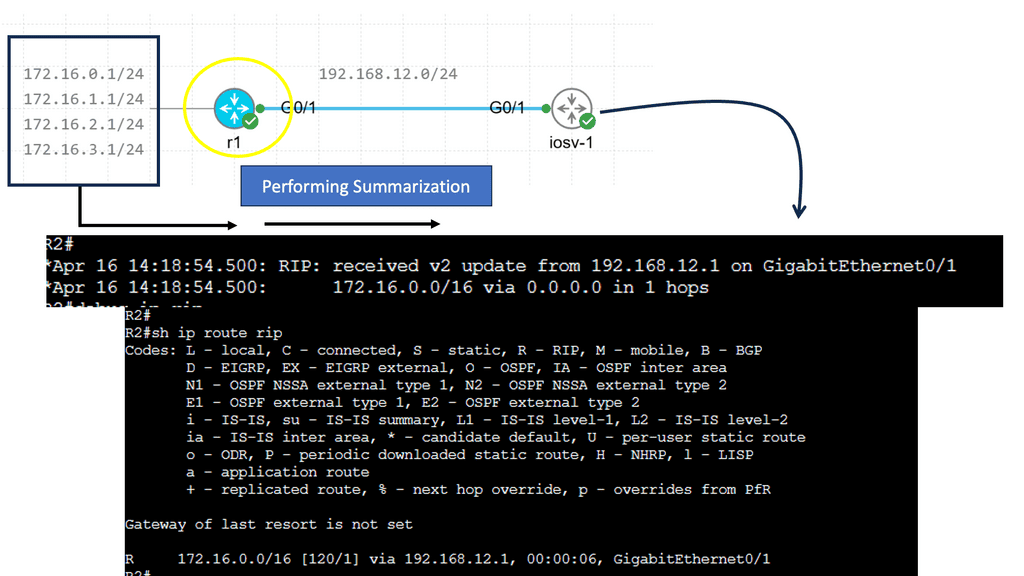
a. Implementing Route Summarization:
Route summarization, also known as route aggregation, is a process that enables the representation of multiple network addresses with a single summarized route. Instead of advertising individual subnets, a summarized route encompasses a range of subnets under one address. This technique contributes to reducing the size of routing tables and optimizing network performance.
The implementation of route summarization offers several advantages. First, it minimizes routers’ memory requirements by reducing the number of entries in their routing tables. This reduction in memory consumption leads to improved router performance and scalability. Second, route summarization enhances network stability and convergence speed by reducing the number of route updates exchanged between routers. Lastly, it improves security by hiding internal network structure, making it harder for potential attackers to gain insights into the network topology.
b. Load Balancing:
Load balancing distributes network traffic across multiple paths, preventing bottlenecks and optimizing resource utilization. Implementing load balancing techniques, such as equal-cost multipath (ECMP) routing, can improve network performance and avoid congestion. Load balancing is distributing the workload across multiple computing resources, such as servers or virtual machines, to ensure optimal utilization and prevent any single resource from being overwhelmed. By evenly distributing incoming requests, load balancing improves performance, enhances reliability, and minimizes downtime.
There are various load-balancing methods employed in different scenarios. Let’s explore a few popular ones:
-Round Robin: This method distributes requests equally among available resources cyclically. Each resource takes turns serving incoming requests, ensuring a fair workload allocation.
-Least Connections: The least connections method directs new requests to the resource with the fewest active connections. This approach prevents any resource from becoming overloaded and ensures efficient utilization of available resources.
-IP Hashing: With IP hashing, requests are distributed based on the client’s IP address. This method ensures that requests from the same client are consistently directed to the same resource, enabling session persistence and maintaining data integrity.
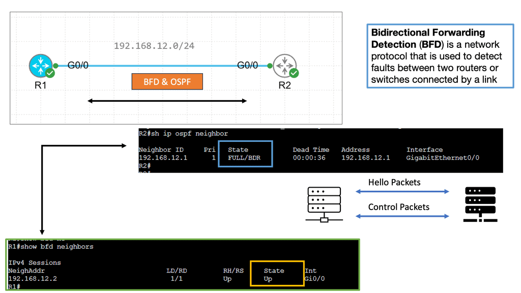
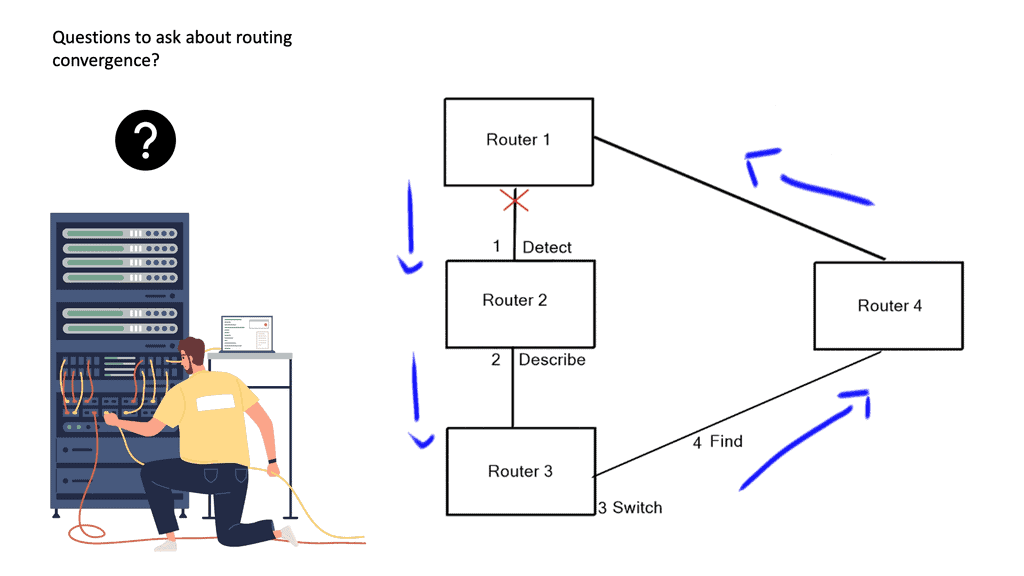
c. Convergence Optimization:
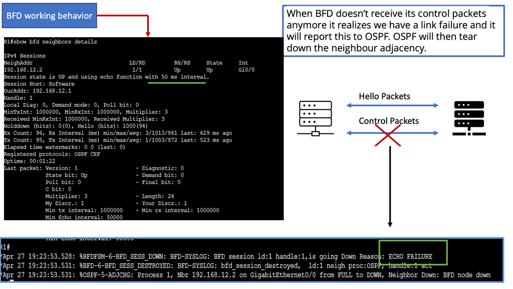
Convergence refers to the process by which routers learn and update routing information. Optimizing convergence time is crucial for minimizing network downtime and ensuring fast rerouting in case of failures. Techniques like Bidirectional Forwarding Detection (BFD) and optimized hello timers can expedite convergence. BFD, in simple terms, is a protocol used to detect faults in the forwarding path between network devices. It provides a mechanism for quickly detecting failures, ensuring quick convergence, and minimizing service disruption. BFD enables real-time connectivity monitoring between devices by exchanging control packets at a high rate.
The implementation of BFD brings several notable benefits to network operators. Firstly, it offers rapid failure detection, reducing the time taken for network convergence. This is particularly crucial in mission-critical environments where downtime can have severe consequences. Additionally, BFD is lightweight and has low overhead, making it suitable for deployment in resource-constrained networks.
Understanding Layer 3 Etherchannel
Layer 3 Etherchannel, or routed Etherchannel, is a network technology that bundles multiple physical links into a single logical interface. Unlike Layer 2 Etherchannel, which operates at the Data Link Layer, Layer 3 Etherchannel extends its capabilities to the Network Layer. This enables load balancing, redundancy, and increased bandwidth utilization across multiple routers or switches.
Configuring Layer 3 Etherchannel involves several steps. Firstly, the physical interfaces that will be part of the Etherchannel need to be identified. Secondly, the appropriate channel protocol, such as Protocol Independent Multicast (PIM) or Open Shortest Path First (OSPF), needs to be chosen. Next, the Layer 3 Etherchannel interface is configured with the desired parameters, including load-balancing algorithms and link priorities. Finally, the Etherchannel is linked to the chosen routing protocol to facilitate dynamic routing and optimal path selection.

Choose the correct topology:
Nodes and links in your network are arranged and connected according to their topology. Topologies have different advantages and disadvantages regarding latency, scalability, redundancy, and cost. A star topology, for example, reduces latency and simplifies management, but it carries a higher load and creates a single point of failure. Multiple paths connect nodes in mesh topologies, increasing complexity overhead, redundancy, and resilience. Choosing the proper topology depends on your network’s size, traffic patterns, and performance goals.
Understanding BGP Route Reflection
BGP Route Reflection allows network administrators to simplify the management of BGP routes within their autonomous systems (AS). It introduces a hierarchical structure by dividing the AS into clusters, where route reflectors are the focal points for route propagation. By doing so, BGP Route Reflection reduces the number of required BGP peering sessions and optimizes route distribution.
The implementation of BGP Route Reflection offers several advantages. Firstly, it reduces the overall complexity of BGP configurations by eliminating the need for full-mesh connectivity among routers within an AS. This simplification leads to improved scalability and easier management of BGP routes. Additionally, BGP Route Reflection enhances route convergence time, as updates can be disseminated more efficiently within the AS.
Route Reflector Hierarchy
Route reflectors play a vital role within the BGP route reflection architecture. They are responsible for reflecting BGP route information to other routers within the same cluster. Establishing a well-designed hierarchy of route reflectors is essential to ensure optimal route propagation and minimize potential issues such as routing loops or suboptimal path selection. We will explore different hierarchy designs and their implications.


Use quality of service techniques.
In quality of service (QoS) techniques, network traffic is prioritized and managed based on its class or category, such as voice, video, or data. Reducing latency by allocating more bandwidth, reducing jitter, or dropping less important packets with QoS techniques for time-sensitive or critical applications is possible. QoS techniques implemented at the network layer include differentiated services (DiffServ) and integrated services (IntServ). Multiprotocol label switching (MPLS) and resource reservation protocol (RSVP) are implemented at the application layer. It would be best to use QoS techniques to guarantee the quality and level of service you want for your applications.
Achieving Low Latency
Understanding Switching
Layer 2 switching, also known as data link layer switching, operates at the second layer of the OSI model. It uses MAC addresses to forward data packets within a local area network (LAN). Unlike layer three routing, which relies on IP addresses, layer 2 switching occurs at wire speed, resulting in minimal latency and optimal performance.
One of the primary advantages of layer 2 switching is its ability to facilitate faster communication between devices within a LAN. By utilizing MAC addresses, layer 2 switches can make forwarding decisions based on the physical address of the destination device, reducing the time required for packet processing. This results in significantly lower latency, making it ideal for real-time applications such as online gaming, high-frequency trading, and video conferencing.
Implementing layer 2 switching requires the deployment of layer 2 switches, specialized networking devices capable of efficiently forwarding data packets based on MAC addresses. These switches are typically equipped with multiple ports to connect various devices within a network. By strategically placing layer 2 switches throughout the network infrastructure, organizations can create low-latency pathways for data transmission, ensuring seamless connectivity and optimal performance.
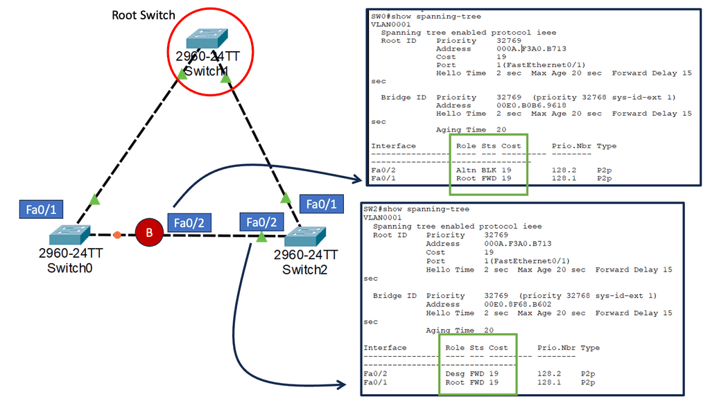
Understanding Spanning-Tree Protocol
STP, a layer 2 protocol, provides loop-free paths in Ethernet networks. It accomplishes this by creating a logical tree that spans all switches within the network. This tree ensures no redundant paths, avoiding loops leading to broadcast storms and network congestion.
While STP is essential for network stability, it can introduce delays during convergence. Convergence refers to the process where the network adapts to changes, such as link failures or network topology modifications. During convergence, STP recalculates the spanning tree, causing temporary disruptions in network traffic. In time-sensitive environments, these disruptions can be problematic.
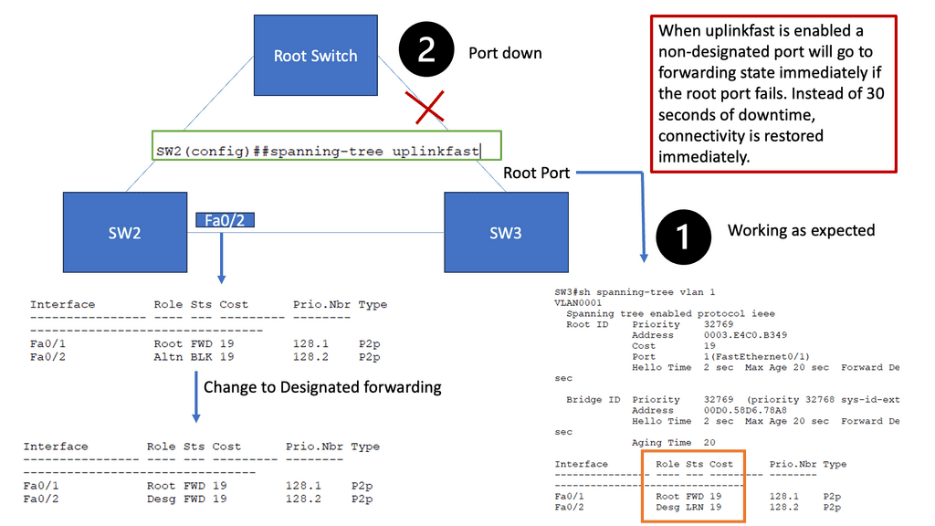
Introducing Spanning-Tree Uplink Fast
Spanning-Tree Uplink Fast is a Cisco proprietary feature designed to reduce the convergence time of STP. When a superior BPDU (Bridge Protocol Data Unit) is received, it immediately transitions from a blocked port to a forwarding state. This feature is typically used on access layer switches that connect to distribution or core switches.
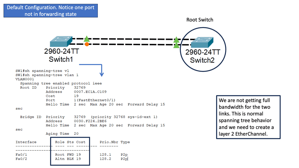
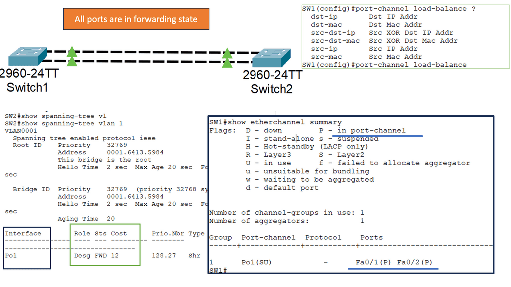
Understanding Layer 2 Etherchannel
Layer 2 Etherchannel, or link aggregation, combines physical links into a single logical link. This provides increased bandwidth and redundancy, enhancing network performance and resilience. Unlike Layer 3 Etherchannel, which operates at the IP layer, Layer 2 Etherchannel operates at the data-link layer, making it suitable for various network topologies and protocols.
Implementing Layer 2 Etherchannel offers several key benefits. Firstly, it allows for load balancing across multiple links, distributing traffic evenly and preventing bottlenecks. Secondly, it provides link redundancy, ensuring uninterrupted network connectivity even during link failures. Moreover, Layer 2 Etherchannel simplifies network management by treating multiple physical links as a single logical interface, reducing complexity and easing configuration tasks.
Keep an eye on your network and troubleshoot any issues.
Monitoring and troubleshooting are essential to identifying and resolving any latency issues in your network. Tools and methods such as ping, traceroute, and network analyzers can measure and analyze your network’s latency and performance. These tools and techniques can also identify and fix network problems like packet loss, congestion, misconfiguration, or faulty hardware. Regular monitoring and troubleshooting are essential for keeping your network running smoothly.
Critical Considerations in Low Latency Design
Designing a low-latency network requires a thorough understanding of various factors. Bandwidth, network topology, latency measurement tools, and quality of service (QoS) policies all play pivotal roles. Choosing the right networking equipment, leveraging advanced routing algorithms, and optimizing data transmission paths are crucial to achieving optimal latency. Moreover, it is essential to consider scalability, security, and cost implications when designing and implementing low-latency networks.
Understanding Low Latency
Low latency, in simple terms, refers to the minimal delay or lag in data transmission between systems. It measures how quickly information can travel from its source to its destination. In network design, achieving low latency involves optimizing various factors such as network architecture, hardware, and protocols. By minimizing latency, businesses can gain a competitive edge, enhance user experiences, and unlock new realms of possibilities.
The Benefits of Low Latency
Low-latency network design offers a plethora of benefits across different industries. In the financial sector, it enables lightning-fast trades, providing traders with a significant advantage in highly volatile markets. Low latency ensures seamless gameplay for online gaming enthusiasts, reducing frustrating lags and enhancing immersion. Beyond finance and gaming, low latency networks improve real-time collaboration, enable telemedicine applications, and enhance the performance of emerging technologies like autonomous vehicles and Internet of Things (IoT) devices.
Advanced Topics
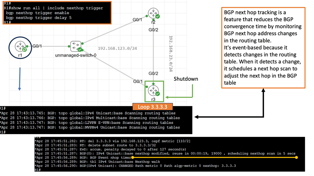
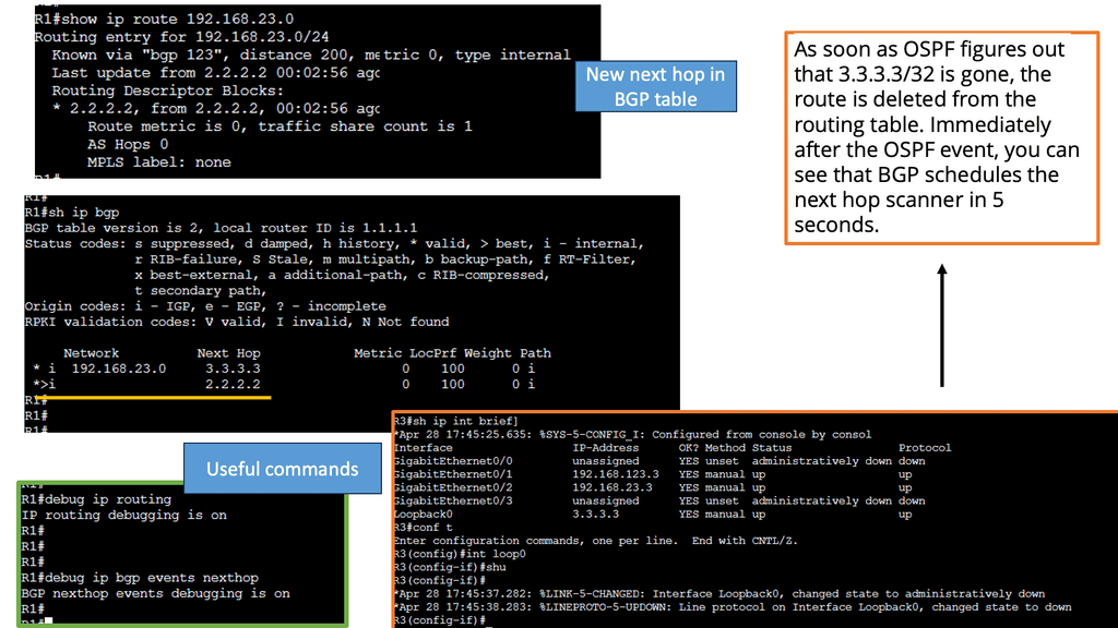
BGP Next Hop Tracking:
BGP next hop refers to the IP address used to reach the destination network. When a BGP router receives an advertisement for a route, it must determine the next hop IP address to forward the traffic. This information is crucial for proper routing and efficient packet delivery.
Next-hop tracking provides several benefits for network operators. First, it enables proactive monitoring of the next-hop IP address, ensuring its reachability and availability. Network administrators can detect and resolve issues promptly by tracking the next hop continuously, reducing downtime, and improving network performance. Additionally, next-hop tracking facilitates efficient load balancing and traffic engineering, allowing for optimal resource utilization.
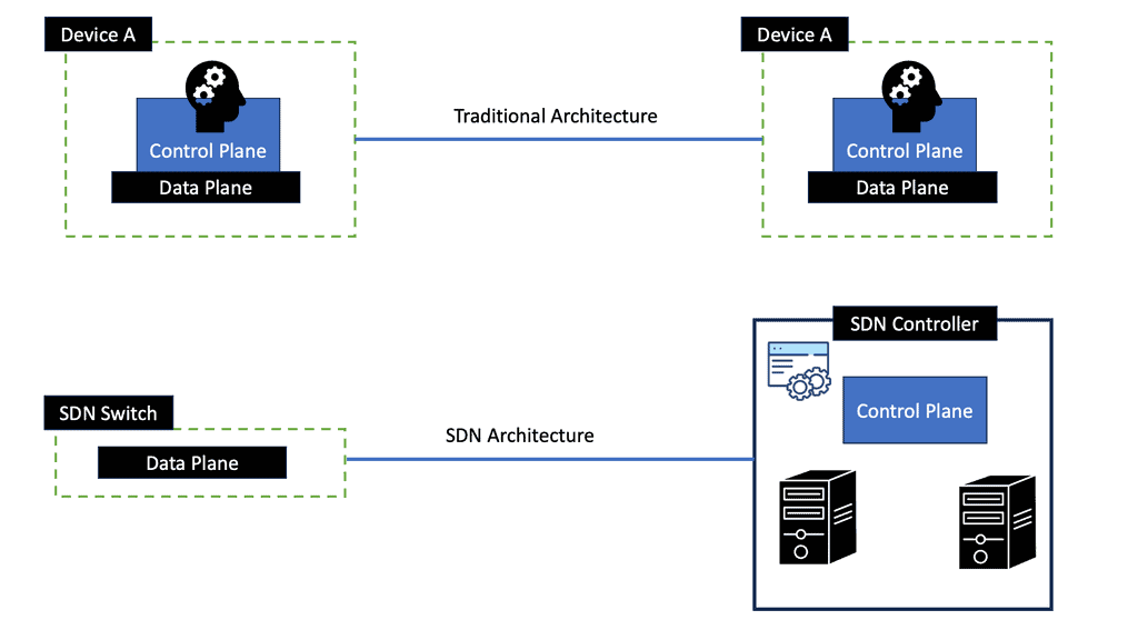
Cutting-Edge Technologies
Low-latency network design is constantly evolving, driven by technological advancements. Innovative solutions are emerging to address latency challenges, from software-defined networking (SDN) to edge computing and content delivery networks (CDNs). SDN, for instance, offers programmable network control, enabling dynamic traffic management and reducing latency. Edge computing brings compute resources closer to end-users, minimizing round-trip times. CDNs optimize content delivery by strategically caching data, reducing global audiences’ latency.
A New Operational Model
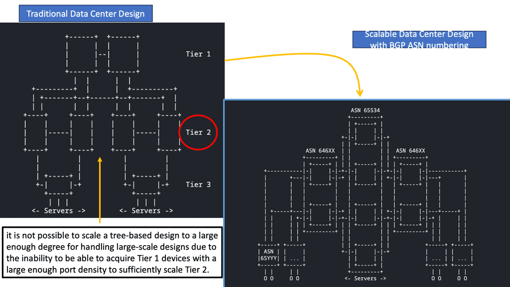
We are now all moving in the direction of the cloud. The requirement is for large data centers that are elastic and scalable. The result of these changes, influenced by innovations and methodology in the server/application world, is that the network industry is experiencing a new operational model. Provisioning must be quick, and designers look to automate network configuration more systematically and in a less error-prone programmatic way. It is challenging to meet these new requirements with traditional data center designs.
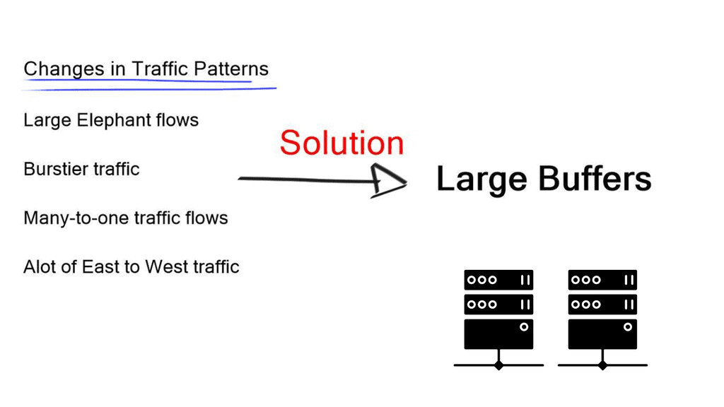
Changing Traffic Flow
Traffic flow has changed, and we have a lot of east-to-west traffic. Existing data center designs focus on north-to-south flows. East-to-west traffic requires changing the architecture from an aggregating-based model to a massive multipathing model. Referred to as Clos networks, leaf and spine designs allow building massive networks with reasonably sized equipment, enabling low-latency network design.
Vendor Example: High-Performance Switch: Cisco Nexus 3000 Series
Featuring switch-on-a-chip (SoC) architecture, the Cisco Nexus 3000 Series switches offer 1 gigabit, 10 gigabit, 40 gigabit, 100 gigabit and 400 gigabit Ethernet capabilities. This series of switches provides line-rate Layer 2 and 3 performance and is suitable for ToR architectures. Combining high performance and low latency with innovations in performance visibility, automation, and time synchronization, this series of switches has established itself as a leader in high-frequency trading (HFT), high-performance computing (HPC), and big data environments. Providing high performance, flexible connectivity, and extensive features, the Cisco Nexus 3000 Series offers 24 to 256 ports.
Latency In Networking. |
|
Related: Before you proceed, you may find the following post helpful:
- Baseline Engineering
- Dropped Packet Test
- SDN Data Center
- Azure ExpressRoute
- Zero Trust SASE
- Service Level Objectives (slos)
Forwarding Features | Control Features |
Network and Storage integration | Bridging without STP |
Multi pathing for Layer 2 and Layer 3 | Integration with server virtualization |
Low latency | Good MAC, ARP and L3 table size |
Optimal Layer 3 forwarding | Deep packet buffers |
Path isolation |
Back to Basics: Network testing.
Network Testing
A stable network results from careful design and testing. Although many vendors often perform exhaustive systems testing and provide this via third-party testing reports, they cannot reproduce every customer’s environment. So, to determine your primary data center design, you must conduct your tests.
Effective testing is the best indicator of production readiness. On the other hand, ineffective testing may lead to a false sense of confidence, causing downtime. Therefore, you should adopt a structured approach to testing as the best way to discover and fix the defects in the least amount of time at the lowest possible cost.
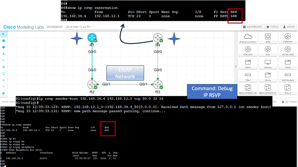
1st Lab Guide: RSVP.
In this example, we will examine RSVP. Resource reservation signals the network and requests a specific bandwidth and delay required for a flow. When the reservation is successful, each network component (primarily routers) reserves the necessary bandwidth and delay.
- First, we need to enable RSVP on all interfaces: ip rsvp bandwidth 128 64
- Then, configure R1 to act like an RSVP host so it will send an RSVP send path message:
- Finally. Configure R4 to respond to this reservation:
What is low latency?
Low latency is the ability of a computing system or network to respond with minimal delay. Actual low latency metrics vary according to the use case. So, what is a low-latency network? A low-latency network has been designed and optimized to reduce latency as much as possible. However, a low-latency network can only improve latency caused by factors outside the network.
We first have to consider latency jitters when they deviate unpredictably from an average; in other words, they are low at one moment and high at the next. For some applications, this unpredictability is more problematic than high latency. We also have ultra-low latency measured in nanoseconds, while low latency is measured in milliseconds. Therefore, ultra-low latency delivers a response much faster, with fewer delays than low latency.
Importance of Low Latency Network Design:
1. Improved User Experience: Low latency networks ensure seamless and uninterrupted communication, enabling users to access and transmit data more efficiently. This is particularly crucial in latency-sensitive applications where any delay can be detrimental.
2. Competitive Advantage: In today’s competitive business landscape, organizations that deliver faster and more responsive services gain a significant edge. Low latency networks enable companies to provide real-time services, enhancing customer satisfaction and loyalty.
3. Support for Emerging Technologies: Low latency networks form the backbone for emerging technologies such as the Internet of Things (IoT), autonomous vehicles, augmented reality (AR), and virtual reality (VR). These technologies require rapid data exchange and response times, which can only be achieved through low-latency network design.
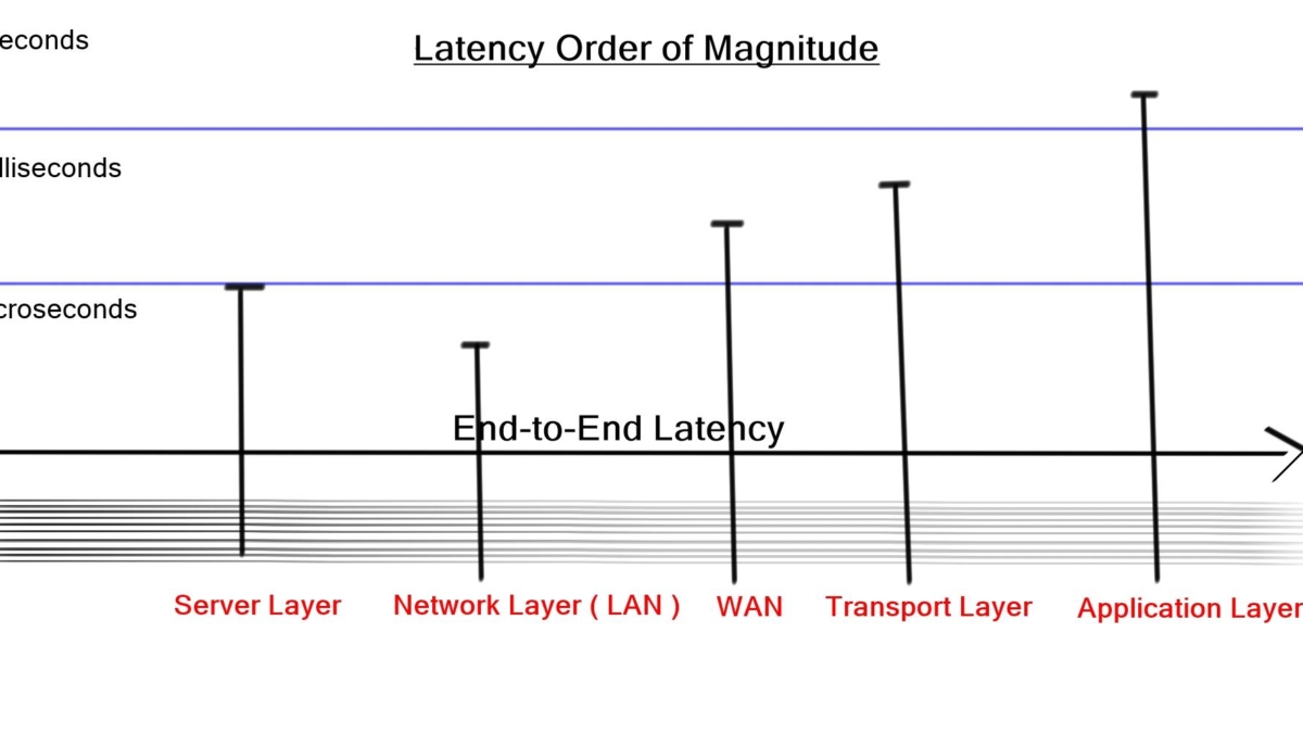
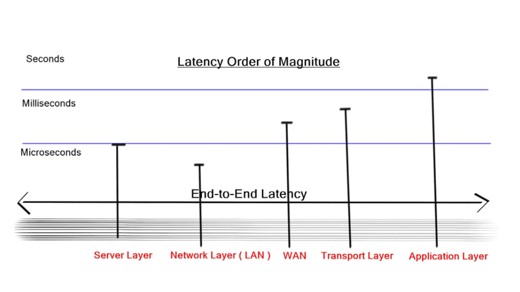
Data Center Latency Requirements
Latency requirements
Intra-data center traffic flows concern us more with latency than outbound traffic flow. High latency between servers degrades performance and results in the ability to send less traffic between two endpoints. Low latency allows you to use as much bandwidth as possible.
A low-lay network design known as Ultra-low latency ( ULL ) data center design is the race to zero. The goal is to design as fast as possible with the lowest end-to-end latency. Latency on an IP/Ethernet switched network can be as low as 50 ns.
High-frequency trading ( HFT ) environments push for this trend, where providing information from stock markets with minimal delay is imperative. HFT environments are different than most DC designs and don’t support virtualization. The Port count is low, and servers are designed in small domains.
It is conceptually similar to how Layer 2 domains should be designed as small Layer 2 network pockets. Applications are grouped to match optimum traffic patterns where many-to-one conversations are reduced. This will reduce the need for buffering, increasing network performance. CX-1 cables are preferred over the more popular optical fiber.
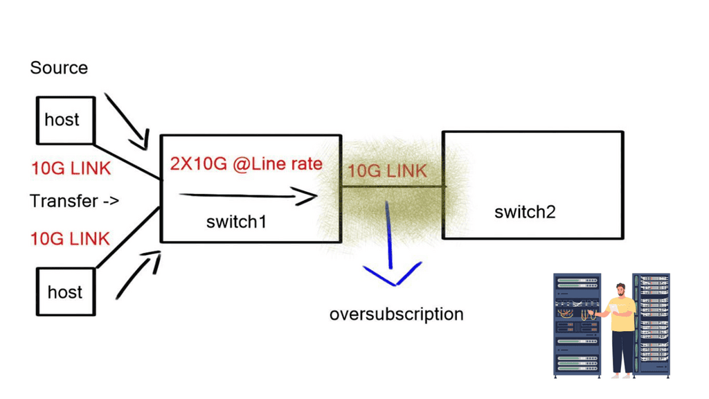
Oversubscription
The optimum low-latency network design should consider and predict the possibility of congestion at critical network points. An unacceptable oversubscription example is a ToR switch with 20 Gbps traffic from servers but only 10 Gbps uplink. This will result in packet drops and poor application performance.
Previous data center designs were 3-tier aggregation model-based ( developed by Cisco ). Now, we are going for 2-tier models. The main design point for this model is the number of ports on the core; more ports on the core result in more extensive networks. Similar design questions would be a) how much routing and b) how much bridging will I implement c) where do I insert my network services modules?
We are now designing networks with lots of tiers—Clos Network. The concept comes from voice networks from around 1953, previously built voice switches with crossbar design. Clos designs give optimum any-to-any connectivity. They require low latency and non-blocking components. Every element should be non-blocking. Multipath technologies deliver a linear increase in oversubscription with each device failure and are better than architectures that degrade during failures.
Lossless transport
Data Center Bridging ( DCB ) offers standards for flow control and queuing. Even if your data center does not use ISCSI (the Internet Small Computer System Interface), TCP elephant flows benefit from lossless transport, improving data center performance. However, research has shown that many TCP flows are below 100Mbps.
The remaining small percentage are elephant flows, which consume 80% of all traffic inside the data center. Due to their size and how TCP operates when an elephant flows and experiences packet drops, it slows down, affecting network performance.
Distributed resource scheduling
VMmobiliy is a VMware tool used for distributed resource scheduling. Load from hypervisors is automatically spread to other underutilized VMs. Other use cases in cloud environments where DC requires dynamic workload placement, and you don’t know where the VM will be in advance.
If you want to retain sessions, keep them in the same subnet. Layer 3 VMotion is too slow as routing protocol convergence will always take a few seconds. In theory, you could optimize timers for routing protocol fast convergence, but in practice, Interior Gateway Protocols ( IGP ) give you eventual consistency.
VMmobiliy
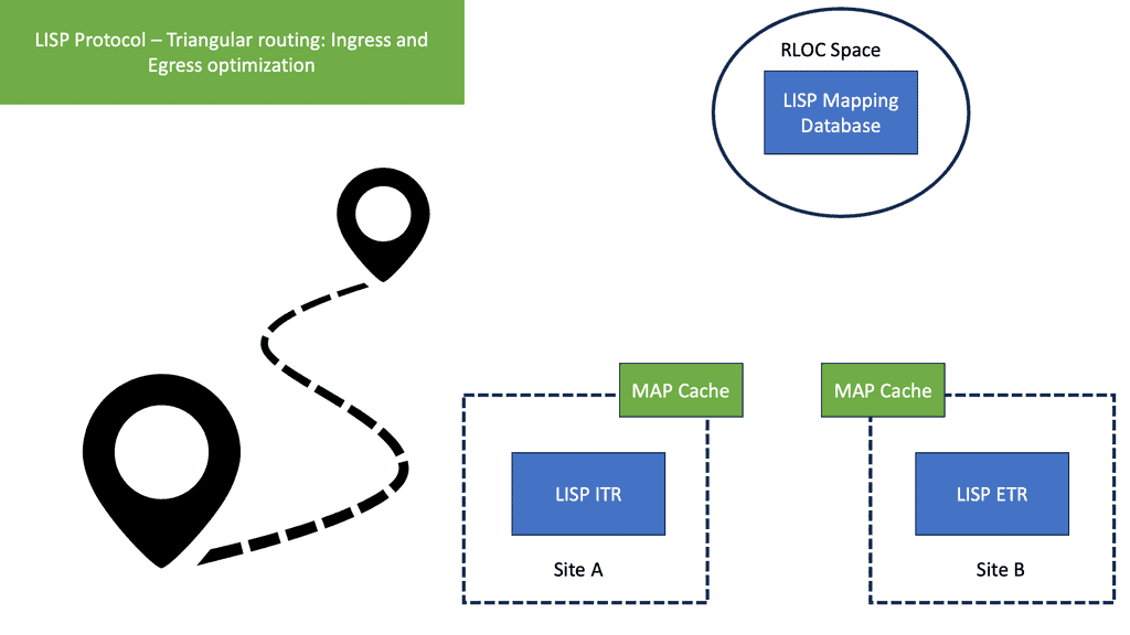
Data Centers require bridging at layer 2 to retain the IP addresses for VMobility. The TCP stack currently has no separation between “who” and “where” you are; the IP address represents both functions. Future implementation with Locator/ID Separation Protocol ( LISP ) divides these two roles, but bridging for VMobility is required until fully implemented.
Spanning Tree Protocol ( STP )
Spanning Tree reduces bandwidth by 50%, and massive multipathing technologies allow you to scale without losing 50% of the link bandwidth. Data centers want to move VMs without distributing traffic flow. VMware has VMotion. Microsoft Hyper-V has Live migration.
Network convergence
The layer 3 network requires many events to be completed before it reaches a fully converged state. In layer 2, when the first broadcast is sent, every switch knows precisely where that switch has moved. There are no mechanisms with Layer 3 to do something similar. Layer 2 networks result in a large broadcast domain.
You may also experience large sub-optimal flows as the Layer 3 next hop will stay the same when you move the VM. Optimum Layer 3 forwarding – what Juniper is doing with Q fabric. Every Layer 3 switch has the same IP address; they can all serve as the next hop—resulting in optimum traffic flow.
Deep packet buffers
We have more DC traffic and elephant flows from distributed databases. Traffic is now becoming very bursty. We also have a lot of microburst traffic. The bursts are so short that they don’t register as high link utilization but are big enough to overflow packet buffers and cause drops. This type of behavior with TCP causes TCP slow start. A slow start with elephant flows is problematic for networks.
Key Considerations for Low Latency Network Design:
1. Network Infrastructure: To achieve low latency, network designers must optimize the infrastructure by reducing bottlenecks, eliminating single points of failure, and ensuring sufficient bandwidth capacity.
2. Proximity: Locating servers and data centers closer to end-users can significantly reduce latency. Data can travel faster by minimizing the physical distance, resulting in lower latency.
3. Traffic Prioritization: Prioritizing latency-sensitive traffic within the network can help ensure that critical data packets are given higher priority, reducing the overall latency.
4. Quality of Service (QoS): Implementing QoS mechanisms allows network administrators to allocate resources based on application requirements. By prioritizing latency-sensitive applications, low latency can be maintained.
5. Optimization Techniques: Various optimization techniques, such as caching, compression, and load balancing, can further reduce latency by minimizing the volume of data transmitted and distributing the workload efficiently.