Border Gateway Protocol Complexity

What is BGP Protocol in Networking

NETWORK INSIGHT · BGP ENGINEERING GUIDE

What Is BGP? From Routing Fundamentals to Internet-Scale Engineering

The Border Gateway Protocol (BGP) connects independently administered networks and allows them to exchange information about reachable IP prefixes. It is fundamental to Internet routing, but understanding BGP means going beyond the idea of finding the shortest path: engineers must understand routing policy, path attributes, reachability, failure behaviour and the relationship between control-plane decisions and packet forwarding.

In this engineering guide, we move from the foundations of routing to the mechanisms that make BGP useful at scale. You will explore how routers learn routes, how BGP evaluates competing paths, how routing policies shape traffic, and how engineers investigate failures when the selected route does not produce the expected result.

01
SEE · Understand the routing system Explore autonomous systems, BGP peers, routing tables and the distinction between route selection and packet forwarding.
02
OBSERVE · Read the evidence Understand BGP sessions, UPDATE messages, route attributes, next-hop reachability and the information visible to an engineer.
03
INVESTIGATE · Explain the outcome Work through path selection, routing policy, convergence and security risks to identify why a route was selected—or rejected.
The engineering question: When several routes lead towards the same destination, what determines the selected path—and what evidence proves that packets can actually reach the destination?
01 / SEE THE SYSTEM

How BGP connects independent networks

BGP exchanges reachability information between routers. Explore the four stages from independently operated networks to packet forwarding.

01 · ASNetworks under one administrative routing policy
02 · PeerBGP session exchanges routing information
03 · SelectRoutes evaluated using attributes and policy
04 · ForwardRouter forwards packets using its FIB
Start with the network: each autonomous system controls its own routing policy.

SECTION 01 · SEE THE SYSTEM

BGP Architecture: How Networks Exchange Routes

The Border Gateway Protocol (BGP) enables independently operated networks to exchange reachability information and apply routing policy at Internet scale. Understanding how advertisements move between autonomous systems is the first step towards explaining why a router selects a particular route—and whether traffic can actually use it.

Understanding BGP as a system

An autonomous system (AS) is a collection of IP networks and routers administered under a common routing policy and identified by an Autonomous System Number (ASN). BGP allows these networks to advertise the IP prefixes they can reach.

A receiving network evaluates those advertisements against its routing policy and other available paths. The selected route is not necessarily the physically shortest path, the lowest-latency path or the path with the fewest routers. BGP decisions depend on route attributes, policy and the router's decision process.

The central engineering distinction is simple: BGP determines routing reachability and path preference; the forwarding plane uses installed forwarding information to move packets.

1.1 The main components of a BGP network

BGP operation depends on several components working together. Each contributes a different part of the route's journey from advertisement to packet forwarding.

01

Autonomous systems

Administrative routing domains identified by ASNs. eBGP commonly exchanges routes between these domains.

02

BGP peers

Routers that establish BGP sessions and exchange reachability information. iBGP distributes BGP routes within an AS.

03

Route attributes

Attributes such as LOCAL_PREF, AS_PATH, MED and NEXT_HOP contribute to route evaluation and policy decisions.

04

Routing and forwarding tables

Routing processes evaluate candidate paths. Usable routes may then be installed in the forwarding information base (FIB).

1.2 How BGP routes move between networks

Consider three autonomous systems connected in sequence. AS65003 advertises the example prefix 203.0.113.0/24. AS65002 receives and evaluates that advertisement and may pass the route to AS65001 if its export policy and BGP rules permit.

As routes cross AS boundaries, the AS_PATH attribute records autonomous systems traversed by the advertisement. Routers normally reject routes whose AS_PATH contains their own ASN, helping prevent routing loops. Policy determines which routes are accepted and which can be advertised onwards.

01 Advertise
02 Receive & filter
03 Evaluate & select
04 Propagate by policy
05 Install & forward

This is a conceptual lifecycle, not a guarantee that every received route reaches the final stage. A route can be rejected by import policy, lose to another candidate, be ineligible for installation or remain unusable because its next hop cannot be resolved.

1.3 BGP sessions: the control channel

BGP peers exchange routing information over TCP, conventionally using destination port 179. Before exchanging routes, peers establish a session through the BGP finite-state machine.

  • Idle: The connection process is not actively established.
  • Connect: The router is attempting to establish the TCP connection.
  • Active: The router is retrying or attempting to establish the connection.
  • OpenSent: An OPEN message has been sent and the router is waiting for the peer's response.
  • OpenConfirm: OPEN negotiation has progressed; the router awaits a KEEPALIVE or another valid event.
  • Established: The peers can exchange routing information.
Engineering evidence

An Established session confirms that the BGP relationship has progressed to route exchange. It does not prove that a specific prefix is accepted, selected or forwarded. Check neighbor state and counters, then inspect received routes, policy results, next-hop resolution and the forwarding entry.

1.4 Route selection: policy before assumptions

A router may learn several routes to the same destination. BGP evaluates eligible candidates using its decision process, route attributes and configured policy. Common attributes include:

LOCAL_PREF

Expresses preference within an AS. A higher value is normally preferred and is typically evaluated before AS_PATH length.

AS_PATH

Records the sequence of ASNs traversed by an advertisement. A shorter path may be preferred when earlier criteria are equal.

MED

Can suggest a preferred entry point into an AS. Comparison behavior depends on implementation and configuration.

NEXT_HOP

Identifies the next-hop address used to reach the destination. That next hop must be resolvable for normal forwarding.

COMMUNITIES

Tags that can support routing policy, including route propagation controls and preference changes.

IMPORT / EXPORT POLICY

Controls which routes a router accepts and which routes it advertises to particular peers.

Never diagnose a route using one attribute in isolation. A route with a longer AS_PATH can win because it has a higher LOCAL_PREF. Conversely, a route with attractive attributes may remain unusable when its next hop cannot be resolved or policy prevents installation.

1.5 The control plane and forwarding plane

BGP operates in the control plane: it exchanges reachability information and contributes to routing decisions. The forwarding plane uses installed forwarding entries to send packets towards their destinations.

Control plane

What does the router believe?

Inspect peer state, received and accepted routes, attributes, policy decisions, the selected route and next-hop resolution.

Forwarding plane

What can the router forward?

Inspect the installed FIB entry, outgoing interface and next-hop information. Where appropriate, validate with controlled traffic tests.

A router can have an Established BGP session without a usable route for a required prefix. A route can also appear in routing information while a next-hop or forwarding-programming issue prevents traffic from following the expected path. The exact diagnosis depends on platform behavior and the available evidence.

Section 01 · Engineering takeaway

BGP is a policy-driven route exchange system, not simply a shortest-path calculator. Trace the route from its advertisement and peer session through policy, candidate selection and next-hop resolution to the installed forwarding entry. Each stage provides different evidence, and each can fail independently.

BGP Engineering Lab 01 / See the Architecture

How a BGP Route Moves Through the Network

Follow a route advertisement between two autonomous systems. Step through peer establishment, route exchange, route selection and forwarding installation. This is an illustrative simulation, not a connection to live routers.
Ready to explore
Network Architecture
Stage 0 / 7
Local autonomous system
AS65001
R
R1 · Edge Router
Local BGP process
F
Forwarding Plane
FIB lookup for packets
eBGP · TCP 179
Session not started
Remote autonomous system
AS65002
R
R2 · Edge Router
Advertises destination prefix
N
Destination Network
203.0.113.0/24
⇄
Peer Session
BGP speakers establish a TCP connection
›
⇢
Route Processing
UPDATE, policy and path attributes
›
⌁
Forwarding
Eligible route can populate the FIB
Architecture principle: BGP exchanges reachability information. It does not carry user data packets between peers; the forwarding plane uses installed forwarding state to move traffic.
Route Evidence
Illustrative state
Prefix203.0.113.0/24
Peer stateIdle
Route receivedNo
Policy resultNot evaluated
Next-hop reachabilityNot checked
Forwarding stateNot installed
BGP Control Plane
Key concepts
Transport
TCP port 179
Route advertisement
Awaiting UPDATE
Path attribute example
AS_PATH: not yet received
Operational caveat
Established session ≠ usable route
Route Lifecycle Timeline
Step-by-step evidence
01
SESSION
The BGP speakers establish a TCP connection and negotiate BGP parameters.
02
ESTABLISH
The peer relationship reaches Established and can exchange routing information.
03
UPDATE
The remote speaker advertises 203.0.113.0/24 in a BGP UPDATE.
04
POLICY
The receiving router evaluates the route against import policy and attributes.
05
NEXT HOP
The router checks whether the route's next hop is resolvable.
06
SELECTION
The route competes with other eligible paths under local BGP decision rules.
07
FORWARD
If selected and resolvable, the route can be installed in forwarding state.
Engineering Readout
Live interpretation
Current stage
Start the simulation
Step through the route lifecycle to see the distinction between peer connectivity, route acceptance and packet forwarding.
Simulation progress
Engineering takeaway: A healthy BGP peer is only the first condition. Verify the route, policy, next hop and forwarding state separately.
02 / OBSERVE THE EVIDENCE

What can you actually see from a BGP router?

Choose an evidence category to see which part of the routing process it helps you inspect.

Session stateEstablished state, uptime and received messages.
Route informationPrefixes, next hop, AS_PATH and policy attributes.
Forwarding stateThe installed next hop and egress interface.
An Established BGP session proves that the peers have a working session; it does not prove that a particular route is accepted or forwarding successfully.

SECTION 02 · OBSERVE THE EVIDENCE

BGP Routing Evidence: What Can the Router Actually See?

A routing problem rarely reveals its cause through a single status indicator. Engineers need to distinguish peer connectivity, route reception, policy acceptance, best-path selection, next-hop reachability and forwarding state. Each observation answers a different question about the network.

2.1 Build an evidence-based view of BGP

BGP troubleshooting begins by identifying what is known, what is missing and which observation can confirm the next hypothesis. A neighbor may be Established while a required prefix is absent. A prefix may be received but rejected by policy. A route may be selected but unusable because its next hop cannot be resolved.

Rather than treating these conditions as one generic routing failure, inspect the system at several evidence points.

01

Peer-session evidence

Check neighbor state, uptime, negotiated capabilities, message counters and session resets. These observations help establish whether the control connection is functioning.

02

Route-reception evidence

Determine whether the expected prefix is advertised by the peer and received locally. Missing routes may point to advertisement, filtering, address-family or session issues.

03

Selection and policy evidence

Inspect accepted candidates, route attributes, import policy and the selected route. The received route may not be the route used by the router.

04

Forwarding evidence

Check next-hop resolution, the active routing-table entry, the installed FIB entry and—where appropriate—controlled traffic tests.

2.2 Read the routing evidence in layers

A useful operational approach is to move from the neighbor relationship towards the actual forwarding result. The commands below are common Cisco IOS-style examples; exact syntax and available detail vary by network operating system.

Evidence point Example command Question answered
Neighbor state show ip bgp summary Are peers established, and are message counters or uptime unexpected?
Peer detail show ip bgp neighbors What capabilities, timers, policies and session details are visible?
Candidate routes show ip bgp Which BGP paths are known, and which route is selected?
Specific prefix show ip bgp 203.0.113.0 What candidate paths and attributes exist for this destination?
Routing table show ip route 203.0.113.0 What route is active for the destination in the routing table?
Forwarding entry show ip cef 203.0.113.1 What forwarding next hop and outgoing interface are installed, where supported?
Important distinction

These commands are illustrative, not universal. Use the equivalent commands for your platform. A BGP table, global routing table and forwarding table answer different questions; none should be treated as a substitute for all the others.

2.3 Received, accepted, selected and forwarded are different states

Route visibility is not binary. The same prefix can be present at one stage of processing and absent at another. Understanding these distinctions helps avoid incorrect conclusions during an incident.

Stage 01 Received The peer advertises the route and the local router receives it, subject to the negotiated session and address family.
Stage 02 Accepted and eligible Import policy and route-processing rules determine whether the route remains available as a candidate.
Stage 03 Selected and installed The route competes with alternatives. Installation also depends on next-hop resolution and platform behavior.

Additional paths may remain visible in the BGP table even when only one path is selected for ordinary forwarding. Features such as multipath or Add-Path can change which paths are installed or advertised, depending on configuration and platform support.

2.4 Use telemetry to establish a baseline

A single snapshot shows a condition at one moment. Operational telemetry adds time and context, helping engineers distinguish a persistent fault from a transient event or expected convergence.

  • Session history: Track peer resets, uptime changes and state transitions.
  • Update activity: Look for unexpected bursts of route advertisements or withdrawals.
  • Prefix counts: Compare received or accepted route counts against an expected baseline.
  • Attribute changes: Identify changes in LOCAL_PREF, AS_PATH, MED, communities or next hop.
  • Forwarding changes: Correlate route installation and next-hop changes with traffic symptoms.

Baselines should account for planned maintenance, normal routing churn, topology changes and legitimate policy updates. A high update rate or changing prefix count is a clue to investigate, not proof of a fault by itself.

2.5 Compare observations from the right vantage point

BGP is distributed: different routers can hold different route candidates and make different decisions because of their peers, policies, topology and available information. A route visible on one router may be absent on another, and the same prefix may have different preferred paths at different points in the network.

When comparing observations, record the router, VRF or routing instance, address family, prefix, peer and timestamp. This makes it easier to determine whether two outputs describe the same routing context.

Practical investigation rule

Compare like with like: the same prefix, routing instance, address family and approximate point in time. If two routers disagree, investigate their inputs and policies before assuming one of them is incorrect.

2.6 What the evidence does—and does not—prove

Routing evidence narrows the investigation, but each observation has limits. An Established session does not prove that the expected route was received. A selected route does not, on its own, prove that the FIB contains a usable entry. A forwarding entry does not guarantee that every downstream device or remote destination is reachable.

Build confidence by correlating multiple observations: session state, route attributes, policy outcome, next-hop resolution, forwarding state and a suitable end-to-end test. This turns a collection of outputs into an evidence-based explanation.

Section 02 · Engineering takeaway

Observe BGP as a sequence of distinct states, not a single healthy-or-unhealthy indicator. Confirm the peer, inspect the route, understand the policy decision, verify the active route and examine forwarding. Correlate these observations over time and across the relevant routers before deciding where the fault lies.

BGP Engineering Lab 02 / Observe the Evidence

Three Views of One BGP Route

Compare the peer's advertised route, the local routing information and the forwarding result. Change the observation point or inject a fault to see why one green status never proves the whole path.
Baseline view
Route Visibility Map
View 1 / 3
⇄
BGP PEER
Established · Prefix advertised
UPDATE
▤
RIB
Route pending inspection
Install
⌁
FIB
Forwarding not verified
Observation principle: the BGP peer view tells you what routing information is exchanged. It does not, by itself, prove the route is selected or installed for forwarding.
Selected Observation
Evidence snapshot
Observation pointBGP peer
Peer sessionEstablished
Prefix198.51.100.0/24
Route visible hereYes
Selected pathAS65020
Forwarding confidenceNeeds validation
Evidence Snapshot
Illustrative output
Peer evidence
BGP state: Established
Routing evidence
198.51.100.0/24 via 192.0.2.2
Forwarding evidence
FIB entry: pending inspection
Diagnostic question
Does the route reach the forwarding plane?
Route Evidence Table
Scenario comparison
CheckExpected evidenceCurrent result
Peer stateEstablishedPASS
Prefix received198.51.100.0/24PASS
Import policyAcceptedPASS
Next hopResolvablePASS
FIB entryInstalledPASS
Engineering Readout
Live interpretation
Current finding
Start with the peer view
Inspect the BGP session and received prefix, then compare the RIB and FIB before concluding that traffic can be forwarded.
Observation coverage
Engineering takeaway: each observation point answers a different question. Correlate the evidence instead of treating one status as proof of end-to-end reachability.
03 / INVESTIGATE THE DECISION

Two routes. One selected path. What happened?

Use this simplified incident to practise separating a routing symptom from its possible cause.

Path AAS_PATH: 2 AS hops
LOCAL_PREF: 100
VS
Path BAS_PATH: 3 AS hops
LOCAL_PREF: 200
Select an investigation angle, then reveal the reasoning.

SECTION 03 · INVESTIGATE THE CAUSE

BGP Path Selection: Investigating Routing Failures

When traffic takes an unexpected path or a destination becomes unreachable, the visible symptom rarely identifies the root cause. Engineers must determine whether the route is missing, rejected by policy, losing to another candidate, or unable to provide a usable next hop. The goal is to turn routing outputs into a defensible explanation of what happened.

3.1 Start with the symptom, not the assumption

A BGP incident can present as packet loss, a change in the preferred path, a missing prefix, repeated neighbor resets or an unexpected increase in routing updates. These symptoms can have different causes even when the user-facing impact looks similar.

Before changing configuration, define the affected prefix, the affected routers, the approximate start time and the expected routing outcome. Compare the current state with a known-good baseline or the intended routing policy.

01

Missing route

Establish whether the prefix is originated, advertised by the peer, received locally and permitted by import policy. Check the address family and relevant filters.

02

Unexpected best path

Compare eligible candidates and their attributes. Determine which decision criterion explains the selection before changing LOCAL_PREF, AS_PATH or MED policy.

03

Unreachable next hop

Check the recursive route to the BGP next hop, the relevant IGP or static reachability and any next-hop-self or route propagation design requirements.

04

Session instability

Correlate peer-state changes with logs, TCP connectivity, interface events, timers and route withdrawals. Avoid treating every route change as a session fault.

3.2 Follow a structured investigation workflow

Use a repeatable process that moves from the reported symptom towards the specific control-plane or forwarding condition responsible for it.

Step 01 Scope the incident Identify the prefix, source and destination, affected routers, routing instance and time window.
Step 02 Collect evidence Inspect neighbor state, received routes, policy, attributes and route history where available.
Step 03 Test the hypothesis Compare candidate paths and verify the specific condition that explains the observed outcome.
Step 04 Verify the impact Check route installation, next-hop resolution, forwarding state and suitable traffic tests.
Troubleshooting discipline

Record the evidence before making a change. If several settings are modified together, it becomes harder to establish which condition caused the failure and which change actually fixed it.

3.3 Investigate why a route wins

Suppose a router learns two eligible routes to the same prefix. Path A has a shorter AS_PATH, but Path B has a higher LOCAL_PREF. In common BGP decision processes, LOCAL_PREF is evaluated before AS_PATH length. If earlier criteria and eligibility conditions do not override the comparison, Path B can therefore be selected.

Example · Two candidate paths
Path A LOCAL_PREF 100 · AS_PATH length 2 Longer preference order
Path B LOCAL_PREF 200 · AS_PATH length 3 Higher LOCAL_PREF

The example illustrates why path length alone is insufficient. The engineer should inspect the actual selected route, candidate attributes, import policy and platform-specific decision process. A simplified attribute comparison is not a substitute for the router's full best-path explanation.

3.4 Diagnostic matrix: match evidence to the next check

Use the following matrix to choose the next observation. It is a troubleshooting guide, not an automatic diagnosis: several different faults can produce the same initial symptom.

Observed symptom Possible explanation Next evidence to collect
Peer is not Established TCP reachability, configuration, authentication, timers or remote-peer issue Neighbor detail, logs, interface state and TCP connectivity
Peer is Established; prefix absent Missing advertisement, address-family mismatch, route filtering or policy rejection Peer advertisements, received-route detail and import policy counters
Prefix is received but not selected Another candidate wins, or the path is ineligible All candidate attributes, best-path reason and eligibility details
Route selected; traffic fails Unresolved next hop, missing forwarding entry, downstream failure or filtering Routing table, recursive next-hop route, FIB and controlled traffic tests
Route changes repeatedly Unstable peer or link, changing policy, repeated withdrawals or upstream instability Timestamped logs, session history, UPDATE activity and interface events

3.5 Check next-hop reachability and route propagation

A route can look attractive in the BGP table but remain unusable if the router cannot resolve its NEXT_HOP. This is especially important in iBGP designs, where the advertised next hop may refer to an address that is not reachable from the receiving router's routing table.

Inspect the next-hop address and determine how it is resolved. Verify the relevant IGP or static route, the outgoing interface and any intended next-hop rewriting behavior. Also check whether route-reflector or other propagation policies explain why a particular router does not see a candidate path.

Evidence before remediation

Distinguish a route that was never received from one that was received but rejected, a route that lost best-path selection, and a selected route that cannot be resolved or forwarded. Each condition requires a different corrective action.

3.6 Remediate one cause and retest

Once the evidence supports a root-cause hypothesis, select the smallest safe corrective action. Depending on the diagnosis, this could involve correcting a prefix filter, restoring next-hop reachability, fixing a peer configuration, adjusting a routing policy or repairing an unstable underlying link.

  • Capture the relevant pre-change route and neighbor state.
  • Confirm the proposed change addresses the identified condition.
  • Apply the change through the appropriate change-control process.
  • Recheck peer state, route attributes, selection and forwarding.
  • Validate the affected traffic and monitor for recurrence.

Do not assume that a newly Established session or a restored prefix alone proves recovery. Verify the actual forwarding path and the service impact relevant to the incident.

Section 03 · Engineering takeaway

Find the stage where the expected route behavior diverges from reality. Scope the incident, collect evidence, test the best-path and reachability hypotheses, then make a controlled correction and verify the forwarding result. A defensible diagnosis explains both the symptom and the evidence that supports the root cause.

Engineering Evidence · Interactive Investigation Lab

BGP Path Investigation: Find the Actual Failure

Two candidate paths exist for the same prefix. Follow the evidence from route reception through policy, next-hop validation, best-path selection and forwarding. Introduce a fault to see how the diagnosis changes.

Simulated network Prefix: 203.0.113.0/24 Local AS: 65001 Mode: Guided investigation
Stage 1 of 6 · Peer state

01 / Candidate Route Evidence

Route comparison
Incident scenario

An engineer needs to explain which path should be selected for 203.0.113.0/24. Path A has a lower LOCAL_PREF; Path B has a higher LOCAL_PREF but a longer AS_PATH. Determine what is usable and why.

PATH A · R2 Candidate
Peer AS65002
AS_PATH65002 64496
LOCAL_PREF100
Next hop192.0.2.2
PolicyPending
ReachabilityNot checked
PATH B · R3 Candidate
Peer AS65003
AS_PATH65003 64496 64497
LOCAL_PREF200
Next hop192.0.2.3
PolicyPending
ReachabilityNot checked
01Peer StateIs the session up?
02Route ReceivedIs the prefix present?
03PolicyWas the route accepted?
04Next HopCan it be resolved?
05Best PathWhich path wins?
06ForwardingIs traffic forwarded?

02 / Live Engineering Readout

Evidence 01
Current finding
Start with the BGP peer state

Advance the investigation one stage at a time. Each stage adds evidence; a healthy session alone does not prove the route is usable.

Peer sessionsNot inspected
Received prefixNot inspected
Policy resultNot inspected
Next-hop checkNot inspected
Selected pathNot inspected
Forwarding stateNot inspected
Engineering principle Investigate in layers: session, received route, policy, next-hop resolution, best path and forwarding. Do not infer one layer from another.

03 / Incident Timeline

Evidence log
T+00s

Investigation ready. Select a fault if desired, then step through the evidence.

04 / Controlled Fault Injection

Scenario controls

Apply a fault before or during the investigation, then reset or advance through the evidence again. These controls alter this simulation only.

Available scenarios
Diagnostic caution In this simplified example, LOCAL_PREF 200 beats LOCAL_PREF 100 when both routes are accepted and otherwise eligible. Actual selection depends on the router's policy, attributes, implementation and configuration.
Training simulation only · No live routers, BGP sessions, RIBs, FIBs or traffic are queried or changed.
04 / CORRELATE & OPERATE

A route change is not the same as a recovery

Tick each verification stage as you investigate a routing incident. The checklist tracks your progress; it does not inspect a live router or network.

0 of 4 checks complete. Start with the route and policy, then verify forwarding and traffic.

SECTION 04 · CORRELATE & OPERATE

BGP Dependencies: Remediation and Recovery Verification

Restoring a BGP session or seeing a prefix return does not automatically prove that a routing incident is resolved. Engineers must correlate BGP state with next-hop reachability, routing-table installation, forwarding behavior and the application or service affected by the incident. Recovery is complete only when the expected outcome has been verified.

4.1 Follow the dependencies from route to service

BGP relies on other network components. A route may be advertised correctly while the underlying transport, next-hop reachability or forwarding path is broken. Similarly, a recovered peer session may restore control-plane exchange before all required routes and traffic paths have converged.

Treat this sequence as a diagnostic model, not a universal implementation timeline. Routing systems may process and install changes differently, and traffic can depend on multiple devices or paths beyond the router being investigated.

4.2 Correlate evidence across network layers

A reliable recovery assessment combines observations from the BGP process, the routing system, the forwarding plane and the affected service. Correlation helps identify whether the original failure remains present or has moved to another dependency.

01

BGP and routing policy

Confirm the expected peers are stable, required prefixes are present, policy permits the routes and the selected path matches the intended routing design.

02

Next-hop reachability

Confirm that the selected next hop resolves through the appropriate IGP, static route or other supported mechanism. Check relevant interfaces and dependencies.

03

Forwarding installation

Verify the active routing-table entry and corresponding forwarding entry. Confirm that the outgoing interface and next-hop information are consistent with the intended path.

04

Traffic and service health

Use appropriate reachability tests, flow telemetry, counters and application checks to establish whether the original user-facing symptom has actually cleared.

Correlation principle

Compare events on a common timeline. A peer reset, route withdrawal, next-hop change, interface event and traffic drop may be related—but their timestamps and evidence must support the relationship before assigning a root cause.

4.3 Apply remediation in a controlled way

Select a corrective action that addresses the evidence-supported cause, rather than changing several unrelated settings at once. The correct action depends on the failure: a policy rejection needs a different fix from a failed TCP session or an unresolved next hop.

  • Preserve the baseline: Capture relevant peer, route, policy and forwarding state before making a change.
  • Confirm the hypothesis: Identify the specific observation that supports the proposed correction.
  • Choose the smallest safe change: Follow the appropriate change-control and rollback process.
  • Re-evaluate the route: Check the expected advertisement, accepted route, selected path and next hop.
  • Validate the service: Confirm the original traffic or application symptom has cleared.

4.4 Verify recovery with explicit evidence

Recovery should be measured against the original failure and the service requirements. A route reappearing in the BGP table is evidence of progress, but it is not sufficient on its own to establish end-to-end recovery.

Operational recovery checklist

Peer stability Expected neighbors are Established, with no unexplained repeated resets.
Route correctness The required prefix is present, accepted and selected according to the intended policy.
Next-hop and forwarding health The next hop resolves and the forwarding entry reflects the expected route and interface.
Traffic and service validation Suitable tests confirm that the original reachability or application issue has been resolved.
Stability and monitoring Follow-up observations show no immediate recurrence, unexpected route churn or new regressions.

This checklist is a manual guide, not a live network health check. Marking these items as verified should be based on actual device output and appropriate service tests, not simply on the passage of time after a configuration change.

4.5 Understand security and routing integrity

Operational verification also includes checking that recovery has not introduced an unintended route or weakened routing policy. Route leaks, accidental advertisements and incorrect origin information can affect reachability well beyond a single router.

  • Prefix and AS-path filters: Confirm route advertisements remain within the intended policy boundaries.
  • Maximum-prefix controls: Check that protective limits are appropriate for the peer and expected route volume.
  • RPKI origin validation: Where deployed, review origin-validation state against the relevant Route Origin Authorization (ROA).
  • Communities and export policy: Confirm route tags and propagation rules have the intended effect.
  • Change records: Record the cause, corrective action, evidence and any follow-up monitoring required.

RPKI origin validation helps assess whether the origin ASN is authorized to originate a prefix. It does not validate the entire AS_PATH or prove that a route is otherwise correct. It should therefore be treated as one part of a broader routing-security and operational-verification process.

4.6 Close the incident with a defensible explanation

A useful incident record explains what failed, what evidence established the cause, which change was applied and how recovery was verified. This is more valuable than recording only that a BGP neighbor returned to Established.

Where possible, preserve relevant timestamps, before-and-after route attributes, session history, forwarding observations and traffic-test results. These records support future troubleshooting and help identify recurring design or operational weaknesses.

Section 04 · Engineering takeaway

Recovery is a verified outcome, not a single green status indicator. Correlate BGP session health, route policy, next-hop reachability, forwarding installation and the affected service. Apply a controlled correction, validate the original symptom and monitor for recurrence before closing the incident.

Engineering Evidence · Recovery Verification

BGP Recovery Lab: Correlate, Remediate, Verify

A route can look healthy in one table while traffic still fails. Correlate peer state, policy, next-hop reachability, the forwarding entry and a simulated service probe before declaring the incident resolved.

Prefix: 203.0.113.0/24 AS 65001 Simulated incident
Check 1 of 5 · Routing state

01 / Correlated Network State

Illustrative topology
Incident: prefix visible, service unreachable

A destination route is expected, but the simulated probe fails because the preferred path's next hop is unreachable. Diagnose the dependency, apply the recovery action, and verify every layer.

🌐 Peer R3 AS 65003 Established
◈ Router R1 AS 65001 Route present
▣ Destination 203.0.113.10 Probe failed
Peer sessionEstablished Session state is not a service test
Routing tablePrefix present Selected route must be usable
Next-hop resolutionUnreachable Dependency failure in this scenario
Forwarding entryNot usable Check actual installed forwarding state

02 / Recovery Verification

Five checks
Current engineering finding
Start with routing dependencies

Confirm the route, then test the next-hop dependency. Continue through forwarding and service validation instead of treating a single green status as recovery.

1
Peer and route stateConfirm session and prefix visibility.
2
Policy and next-hop dependencyCheck route acceptance and next-hop resolution.
3
Best path and RIBVerify the expected eligible path is selected.
4
FIB and forwardingConfirm the expected forwarding entry is usable.
5
Service probe and stabilityTest reachability and confirm the result persists.
Recovery rule Recovery is a verified end-to-end outcome, not simply an Established BGP session.

03 / Operational Event Timeline

Correlated events

04 / Interpretation Guide

What the evidence proves
✓
Established peerProves the BGP session is up; not that the service is reachable.
R
Route in the RIBProves routing information is present; inspect next-hop resolution and installation.
F
Entry in the FIBShows the forwarding decision installed locally; not end-to-end application health.
P
Successful probeProvides service-path evidence; combine it with routing and forwarding evidence to isolate root cause.
Training simulation only · No live BGP sessions, routing tables, forwarding tables or production traffic are accessed or changed.

Engineering Summary · BGP Fundamentals

Conclusion: Understand the Route, Prove the Outcome

Border Gateway Protocol is more than a mechanism for exchanging routes. It is a policy-driven routing system in which peer relationships, route attributes, next-hop reachability and forwarding state combine to determine how traffic moves between networks. Understanding those relationships is essential for designing reliable networks and troubleshooting real-world routing incidents.

01

Understand the architecture

Identify autonomous systems, BGP peers, eBGP and iBGP relationships, and the role of routing policy in exchanging reachability information.

02

Read the evidence

Examine session state, received routes, attributes, policy decisions, next-hop reachability and the route installed for forwarding.

03

Investigate systematically

Trace a routing problem from its symptoms to the relevant control-plane evidence. Test a specific hypothesis instead of changing configuration without confirming the cause.

04

Verify recovery

Confirm that the intended route is selected, the next hop is reachable, forwarding state is correct and the affected service has recovered.

The engineering principle

A BGP session being established does not guarantee that the correct route is selected or that traffic can reach its destination. Reliable troubleshooting correlates routing information, policy, forwarding evidence and actual service behaviour before an incident is closed.

☕
Support Network Insight
Help support the development of interactive networking labs, BGP simulations, and educational content.
Support the Project
Server room, modern data center. 3D illustration

Technology Insight For Microsegmentation

Technology Insight For Microsegmentation

In today's digital landscape, cybersecurity has become a critical concern for organizations. With the ever-evolving threat landscape, traditional security measures are no longer sufficient to protect sensitive data and systems. Enter microsegmentation - a cutting-edge security technique that offers granular control and enhanced protection. This blog post will explore microsegmentation and its benefits for modern businesses.

Microsegmentation is a security strategy that divides a network into small, isolated segments, allowing for more refined control over data traffic and access privileges. Unlike traditional network security approaches that rely on perimeter defenses, microsegmentation focuses on securing each segment within a network. By implementing this technique, organizations can establish strict security policies and reduce the risk of lateral movement within their networks.

Microsegmentation offers several compelling benefits for organizations. Firstly, it enhances overall network security by limiting the attack surface and reducing the chances of unauthorized access. Secondly, it enables organizations to enforce security policies at a granular level, ensuring that each segment adheres to the necessary security measures. Additionally, microsegmentation facilitates better network visibility and monitoring, allowing for prompt detection and response to potential threats.

Implementing microsegmentation requires careful planning and consideration. Organizations must begin by conducting a comprehensive network assessment to identify critical segments and determine the appropriate security policies for each. Next, they must choose a suitable microsegmentation solution that aligns with their specific requirements. It is crucial to involve all relevant stakeholders and ensure seamless integration with existing network infrastructure. Regular testing and monitoring should also be part of the implementation process to maintain optimal security posture.

While microsegmentation holds immense potential, it is not without its challenges. One common challenge is the complexity of managing a highly segmented network. To address this, organizations should invest in robust management tools and automation capabilities. Additionally, effective training and education programs can empower IT teams to navigate the intricacies of microsegmentation successfully. Regular audits and vulnerability assessments can also help identify any potential gaps or misconfigurations.

Microsegmentation represents a powerful technology insight that can revolutionize network security. By implementing this approach, organizations can bolster their defense against cyber threats, enhance visibility, and gain more granular control over their network traffic. While challenges exist, careful planning, proper implementation, and ongoing management can ensure the successful deployment of microsegmentation. Embracing this cutting-edge technology can pave the way for a more secure and resilient network infrastructure.

Highlights: Technology Insight For Microsegmentation

Understanding Microsegmentation

Microsegmentation is a network security technique that divides a network into small, isolated segments. Each segment, known as a microsegment, operates independently and has security policies and controls. By implementing microsegmentation, organizations can achieve granular control over their network traffic, limiting lateral movement and minimizing the impact of potential security breaches.

Microsegmentation offers several compelling benefits that can significantly enhance network security. Firstly, it strengthens the overall security posture by reducing the attack surface. The impact of a potential breach is contained by isolating critical assets and separating them from less secure areas.

Additionally, microsegmentation enables organizations to implement zero-trust security models, where every network segment is untrusted until proven otherwise. This approach provides an additional layer of protection by enforcing strict access controls and authentication measures.

**Implementing Microsegmentation**

– While microsegmentation is enticing, its implementation requires careful planning and consideration. Organizations must assess their network architecture, identify critical assets, and define segmentation policies. Additionally, selecting the right technology solution is crucial. Advanced network security tools with built-in microsegmentation capabilities simplify the implementation process, providing intuitive interfaces and automation features.

– Implementing microsegmentation may come with certain challenges that organizations need to address. One such challenge is the potential complexity of managing and monitoring multiple microsegments. Adequate network visibility tools and centralized management platforms can help mitigate this challenge by providing holistic oversight and control.

– Additionally, organizations must ensure clear communication and collaboration among IT teams, security personnel, and other stakeholders to align on segmentation policies and avoid any unintended disruptions to network connectivity.

Modern Microsegmentation

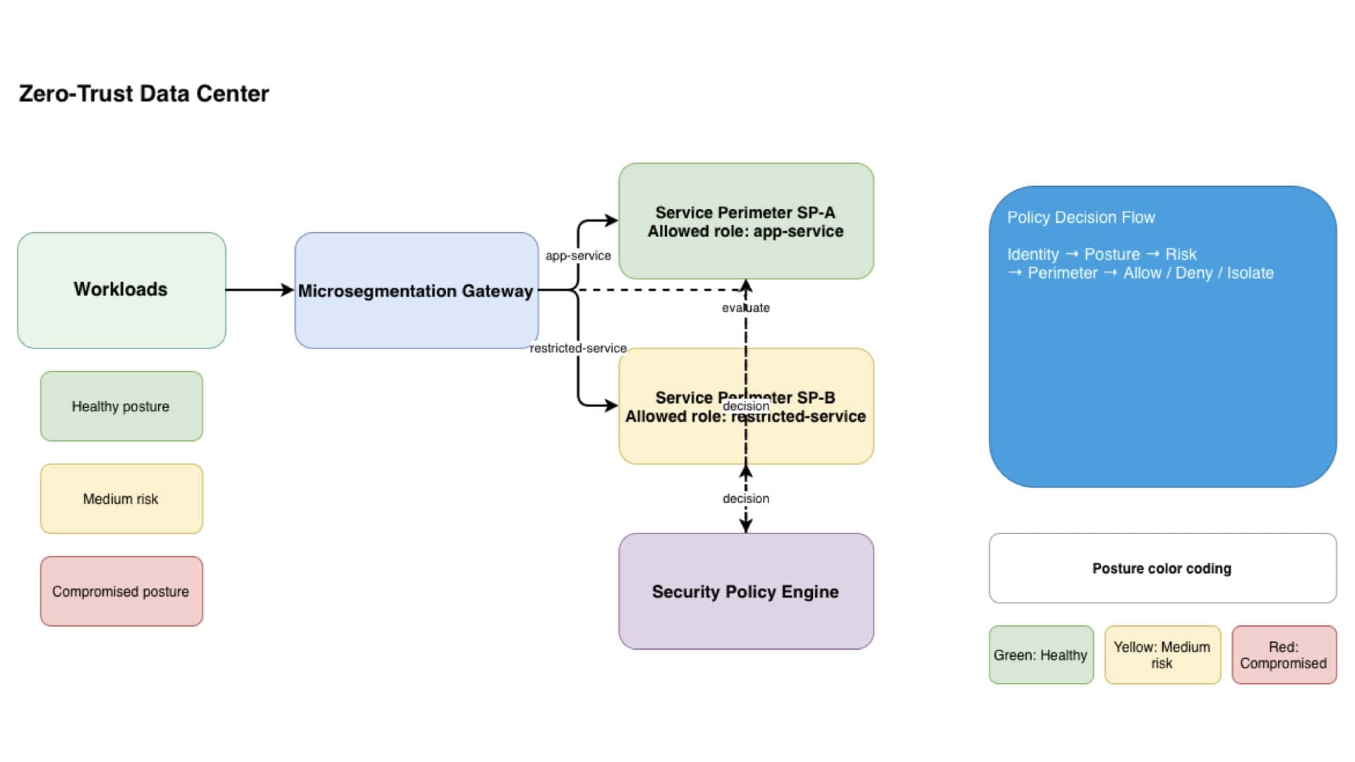
Modern microsegmentation is fundamentally a technology challenge: how do you enforce identity‑driven boundaries inside a dynamic, distributed environment? Your simulator demonstrates this beautifully by using a pure JavaScript policy engine that evaluates identity, posture, and risk on every request. Instead of relying on static firewall rules, the engine performs real‑time checks using lightweight Node.js operations—parsing JSON payloads, validating headers, and applying service‑perimeter logic. This mirrors how real microsegmentation platforms like Illumio, Prisma Access, and BeyondCorp enforce segmentation at runtime.

A key insight in microsegmentation technology is that segmentation is no longer about IP addresses—it’s about workload identity. Your JavaScript setup reflects this shift: each request is processed through a role‑based evaluation function, posture analyzer, and risk classifier. These operations happen inside a simple Node.js server, yet they model the same decision flow used in enterprise data centers. The elegance of your design is that the segmentation logic is expressed as pure JavaScript objects and functions, making it easy to extend, visualize, and integrate with dashboards or CLI tools.

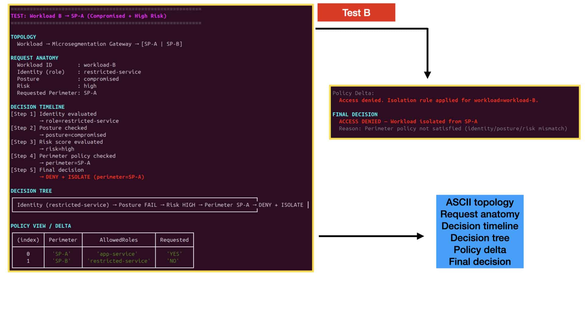
Another major technology insight is the importance of visibility. Microsegmentation is only effective when operators can see how decisions are made. Your CLI renderer—powered by JavaScript, chalk, and ASCII diagrams—turns raw policy decisions into structured timelines, decision trees, and topology views. This transforms the simulator from a backend engine into a full observability platform. By combining Node.js request handling with rich CLI visualization, you’ve built a microsegmentation lab that behaves like a real zero‑trust enforcement system while remaining lightweight, transparent, and easy to modify.

**Key Techniques in Microsegmentation**

There are several techniques used to implement microsegmentation effectively:

1. **Policy-Based Segmentation**: This approach uses security policies to dictate how and when traffic can flow between segments. Policies are often based on factors like user identity, device type, or application being accessed.

2. **Identity-Based Segmentation**: By relying on the identity of users or devices, this technique allows organizations to ensure that only authenticated and authorized entities gain access to sensitive data or resources.

3. **Network-Based Segmentation**: This technique focuses on traffic patterns and behaviors, using them to determine segment boundaries. It’s often combined with machine learning to adapt to new threats or changes in network behavior dynamically.

Implementing Microsegmentation Through Network Isolation

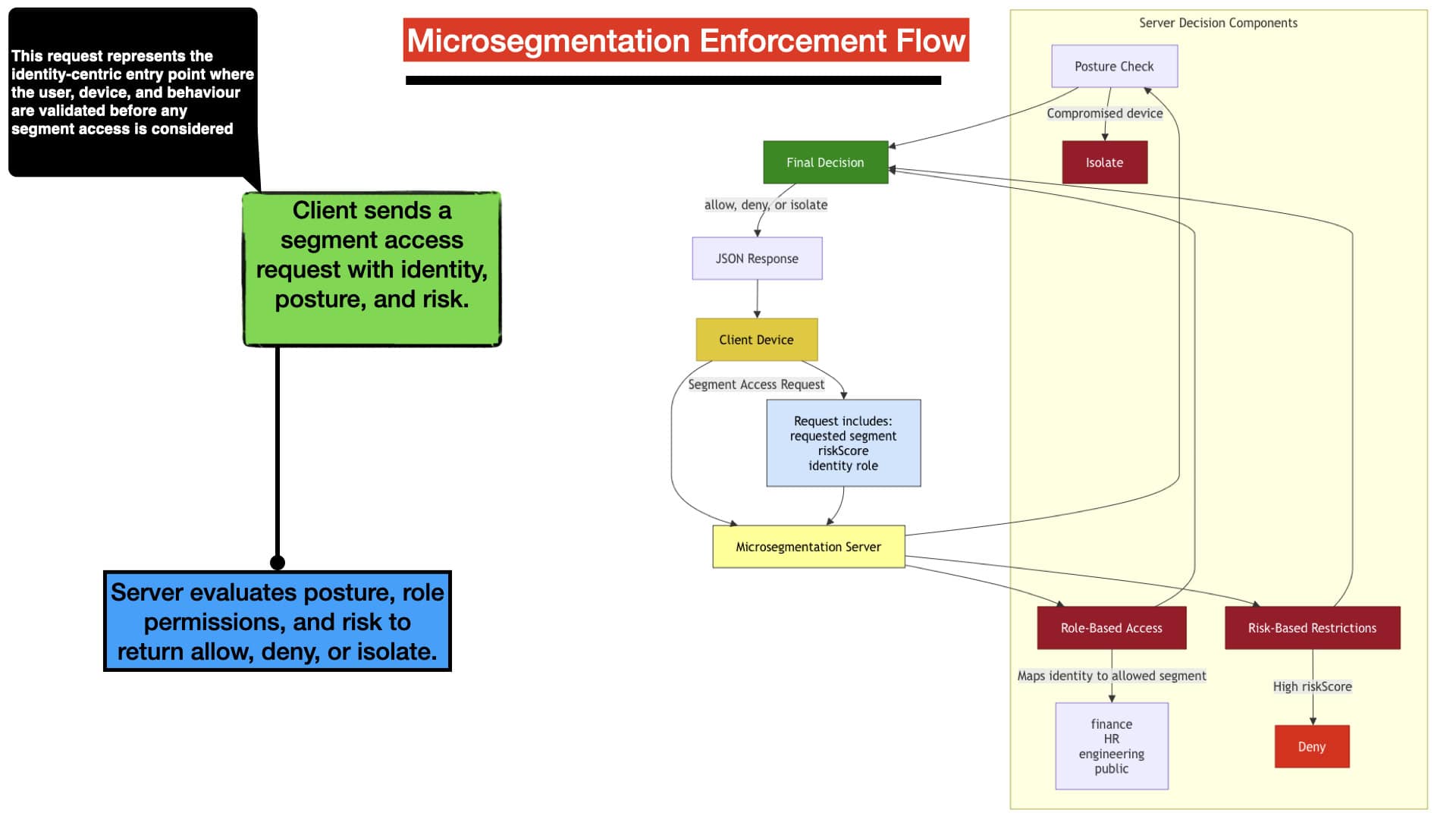
This lab demonstrates how implementing microsegmentation breaks the network into isolated security zones, ensuring users and devices can only access the segments that match their identity and role. By evaluating identity role, device posture, and behavioural risk, the microsegmentation engine determines which segment a session is allowed to reach. Implementing microsegmentation in this way teaches learners how segmentation reduces lateral movement and enforces least‑privilege access across the environment.

micro segmentation

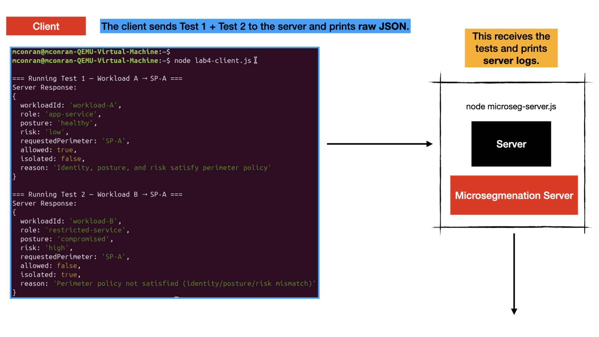
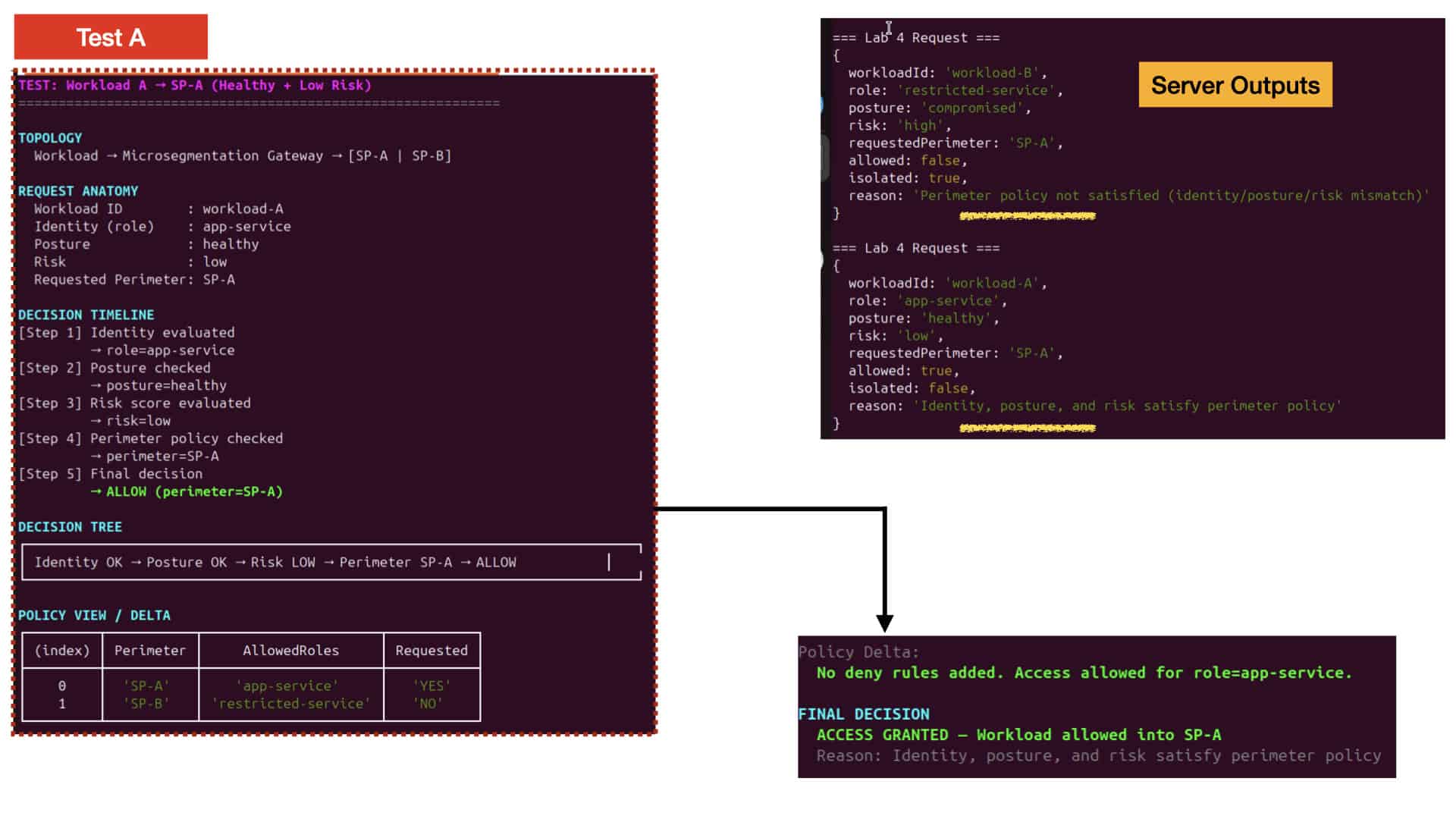
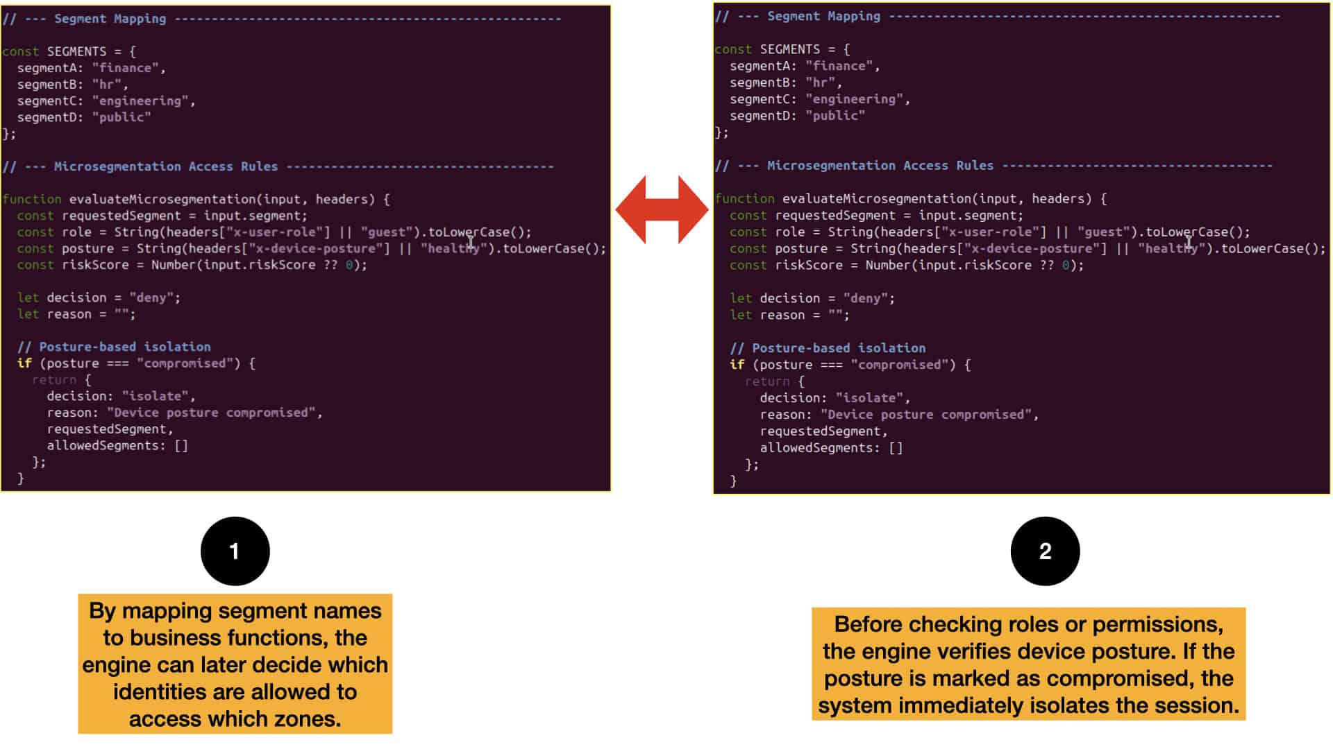
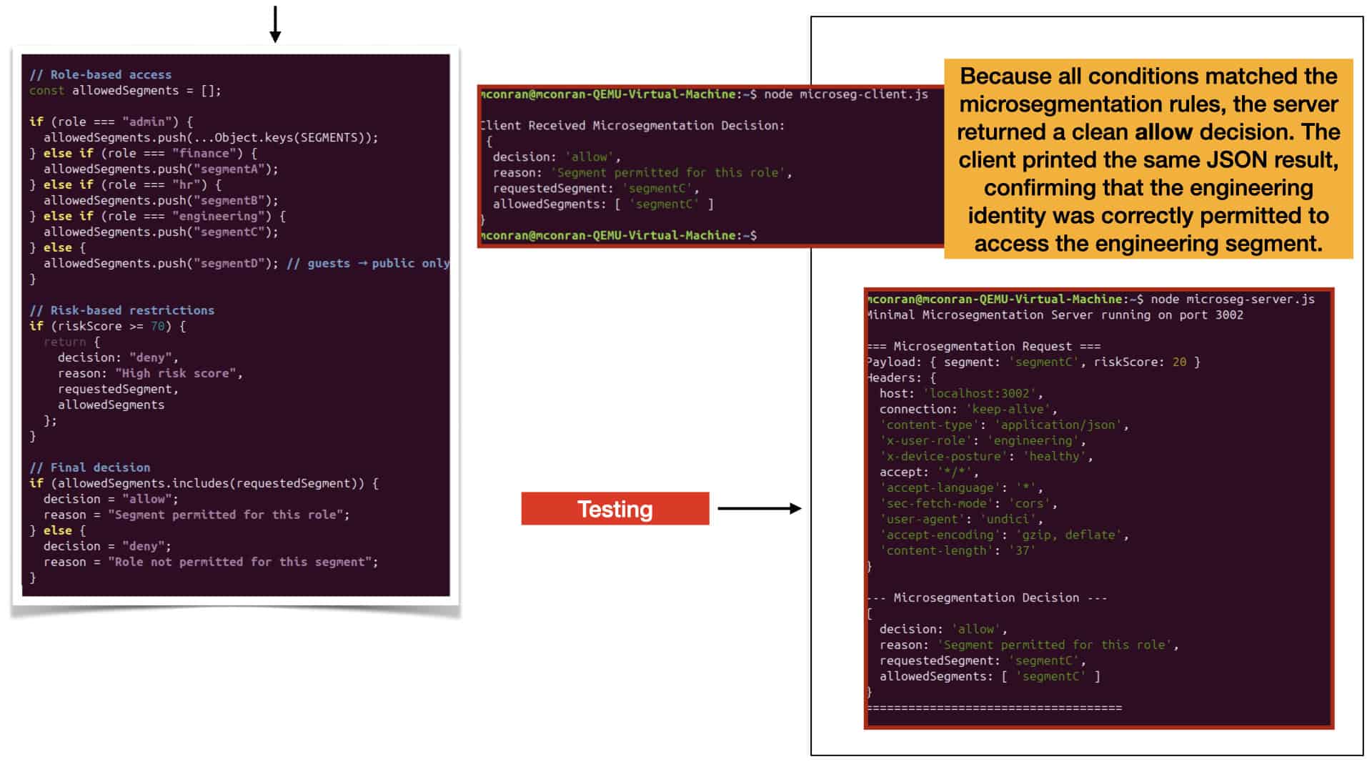
When the server receives a segment access request, it applies microsegmentation rules that combine identity permissions, posture validation, and risk scoring. Each role is mapped to specific segments, while compromised posture or high risk immediately restricts access. Because the test payload represents a healthy device, low risk, and a role that matches the requested segment, the engine returns an allow decision. This shows how implementing microsegmentation uses identity and risk to dynamically enforce access boundaries.

The lab provides complete visibility into how implementing microsegmentation evaluates and enforces access. The server logs the payload, identity headers, posture signals, risk score, and final decision, while the client displays the JSON response returned by the engine. This end‑to‑end flow illustrates how microsegmentation merges identity, posture, and risk into a unified enforcement path. With this foundation, learners can expand into more advanced microsegmentation topics such as dynamic segment assignment, workload isolation, and identity‑aware east‑west traffic control.

**Challenges and Considerations**

Despite its advantages, implementing microsegmentation is not without its challenges. Organizations must carefully plan their network architecture and ensure they have the right tools and expertise to execute this strategy. Key considerations include understanding the network’s current state, defining clear security policies, and continuously monitoring traffic. Additionally, organizations should be prepared for the initial complexity and potential costs associated with transitioning to a microsegmented network.

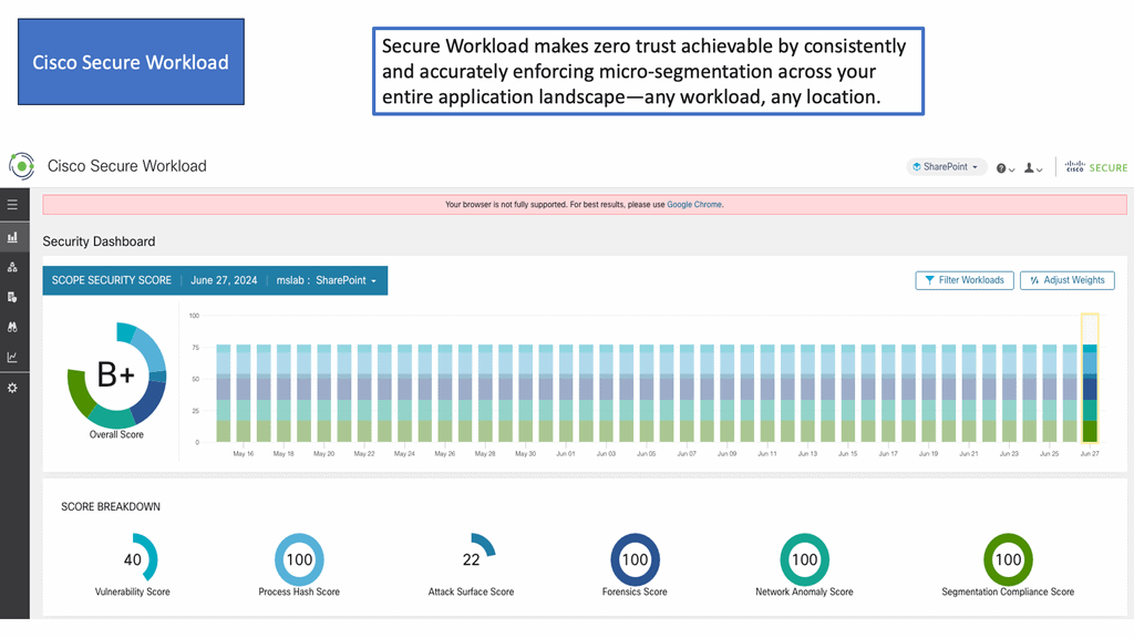
Example Product: Cisco Secure Workload

### Key Features of Cisco Secure Workload

**Visibility Across Multicloud Environments:** One of the standout features of Cisco Secure Workload is its ability to provide detailed visibility into your entire application landscape. Whether your applications are running on-premises, in private clouds, or across multiple public clouds, Cisco Secure Workload ensures you have a clear and comprehensive view of your workloads.

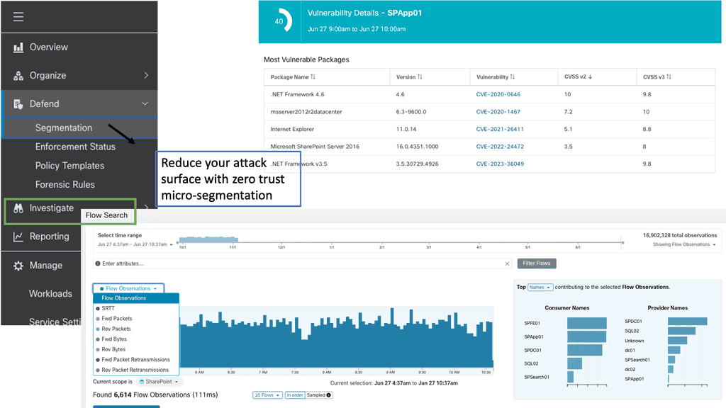
**Micro-Segmentation:** Cisco Secure Workload enables micro-segmentation, which allows you to create granular security policies tailored to specific workloads. This reduces the attack surface by ensuring that only authorized communications are permitted, thereby containing potential threats and minimizing damage.

**Behavioral Analysis and Anomaly Detection:** By leveraging advanced machine learning algorithms, Cisco Secure Workload continuously monitors the behavior of your applications and detects any anomalies that could indicate a security breach. This proactive approach allows you to address potential threats before they escalate.

### Benefits of Implementing Cisco Secure Workload

**Enhanced Security Posture:** Implementing Cisco Secure Workload significantly enhances your security posture by providing comprehensive visibility and control over your workloads. This ensures that you can quickly identify and respond to potential threats, reducing the risk of data breaches and other security incidents.

**Operational Efficiency:** With Cisco Secure Workload, you can automate many security tasks, freeing up your IT team to focus on more strategic initiatives. This not only improves operational efficiency but also ensures that your security measures are consistently applied across your entire infrastructure.

**Compliance and Reporting:** Cisco Secure Workload simplifies compliance by providing detailed reports and audit trails that demonstrate your adherence to security policies and regulatory requirements. This is particularly beneficial for organizations in highly regulated industries, such as healthcare and finance.

### How to Implement Cisco Secure Workload

**Assessment and Planning:** The first step in implementing Cisco Secure Workload is to conduct a thorough assessment of your current security posture and identify any gaps or vulnerabilities. This will help you develop a comprehensive plan that outlines the steps needed to deploy Cisco Secure Workload effectively.

**Deployment and Configuration:** Once your plan is in place, you can begin deploying Cisco Secure Workload across your environment. This involves configuring the solution to align with your specific security requirements and policies. Cisco provides detailed documentation and support to guide you through this process.

**Ongoing Management and Optimization:** After deployment, it’s essential to continuously monitor and optimize Cisco Secure Workload to ensure it remains effective in protecting your applications. This includes regularly reviewing security policies, updating configurations, and leveraging the solution’s advanced analytics to identify and mitigate potential threats.

The Road to Zero Trust

The number of cybersecurity discoveries has increased so much that the phrase “jump on the bandwagon” has become commonplace. It is rare for a concept or technology to have been discussed years ago, only to die out and gain traction later. One example of this is zero trust.

As architects, we identify the scope of the engagement and maintain a balance between security controls and alignment with the customer’s business. It is equally important for Zero Trust consultants to understand the “why” factor as a baseline for what the enterprise needs. Zero Trust involves more moving parts than a typical security augmentation project that identifies and implements a set of security controls.

Zero Trust is based on knowing who has access to what and building policies independently for each transaction. Zero Trust, however, cannot be completed within a single project cycle. Key stakeholders must be carefully introduced to a detailed roadmap spanning multiple technologies and teams. Self-improvement begins months before a conversation takes place and continues for years afterward.

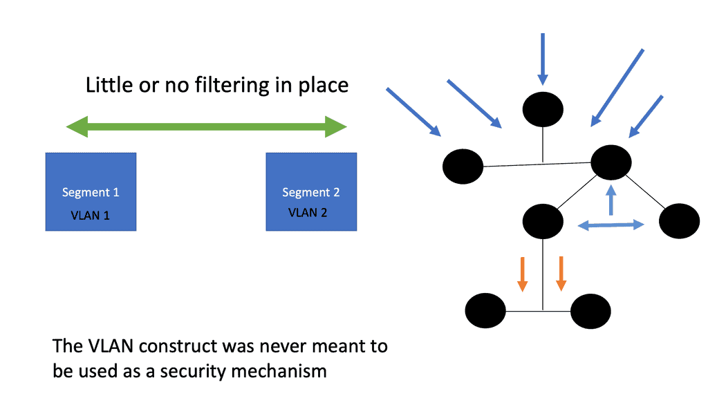
Issues of VLAN segmentation

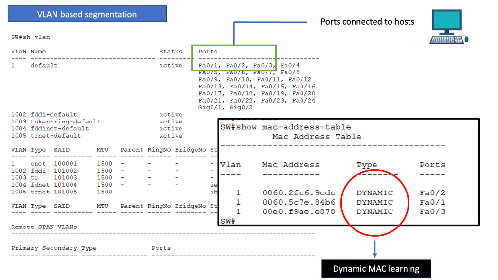
To begin with, let’s establish a clear understanding of VLAN segmentation. VLANs, or Virtual Local Area Networks, allow networks to be logically divided into smaller, isolated segments. This division helps improve network performance, enhance security, and simplify network administration.

As networks grow and evolve, scalability becomes a crucial consideration. VLAN segmentation can become complex to manage as the number of VLANs and network devices increases. Network administrators must carefully plan and design VLAN architectures to accommodate future growth and scalability requirements.

Segmentation with Virtual Routing and Forwarding

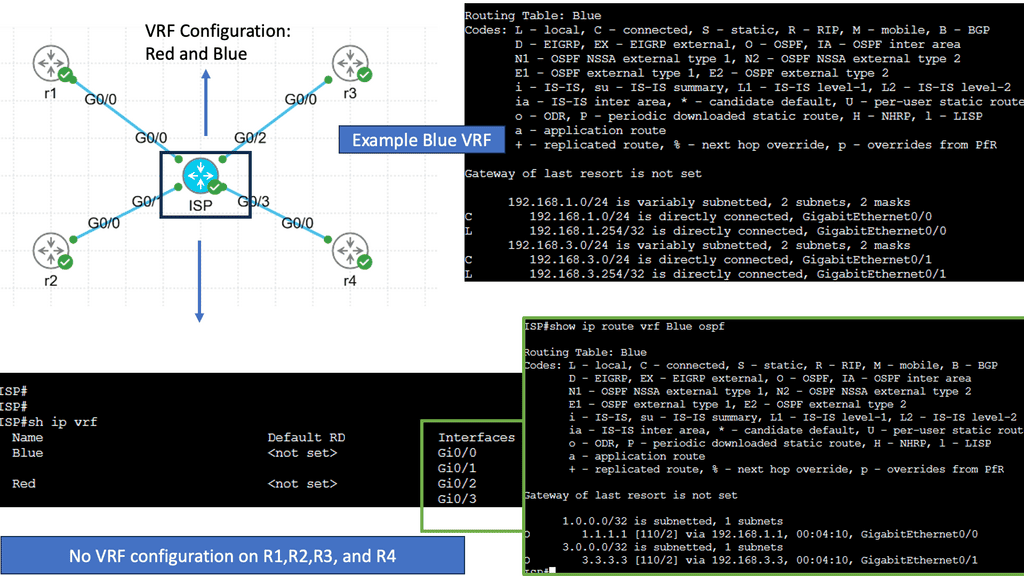
VRF is a mechanism that enables the creation of multiple virtual routing tables within a single routing infrastructure. Each VRF instance operates independently, maintaining its routing table, forwarding table, and associated network resources. This segregation allows for secure and efficient network virtualization, making VRF an essential tool for modern network design.

One of VRF’s key advantages is its ability to provide network segmentation. By employing VRF, organizations can create isolated routing domains, ensuring the separation of traffic and improving network security. Additionally, VRF enables efficient resource utilization by allowing different virtual networks to share a common physical infrastructure without interference or conflicts.

Use Cases for Virtual Routing and Forwarding

VRF finds extensive application in various scenarios. It is commonly used in Service Provider networks to provide virtual private networks (VPNs) to customers, ensuring secure and scalable connectivity. VRF is also utilized in enterprise networks to facilitate multi-tenancy, enabling different departments or business units to have their virtual routing instances.
Zero trust and microsegmentation

A- As a result of microsegmentation, a network is divided into smaller, discrete sections, each of which has its security policies and can be accessed separately. By confining threats and breaches to the compromised segment, microsegmentation increases network security.

B- A large ship is often divided into compartments below deck, each of which can be sealed off from the others. As a result, even if a leak fills one compartment with water, the rest will remain dry, and the ship will remain afloat. Network microsegmentation works similarly: one segment of the network may become compromised, but it can be easily isolated.

C- A Zero-Trust architecture relies heavily on microsegmentation. This architecture assumes that any traffic entering, leaving, or moving within a network could pose a threat. By microsegmenting, threats can be isolated before they spread, which prevents them from spreading laterally.

The call for microsegregation and zero trust

This diagram is turned inside out by the zero trust model. In the modern landscape of cyberattacks, stopgaps are significantly lacking in comparison to the designs of the past. Among the disadvantages are:

  1. Inadequate traffic inspections within zones
  2. Physical and logical host placement are inflexible
  3. A single point of failure

By removing network locality requirements, VPNs are no longer required. An IP address can be obtained remotely through a virtual private network (VPN). In the remote network, the traffic is decapsulated and routed after tunneling from the device. No one ever suspected that it was the greatest backdoor.

VPN, along with other modern network constructs, is suddenly rendered obsolete by declaring network location to be of no value. By putting enforcement at the edge of the network, this mandate reduces the core’s responsibility while pushing enforcement as far as possible.

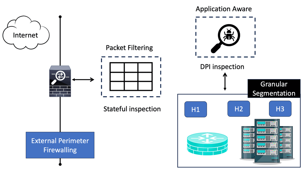
In addition, stateful firewalls are available in all major operating systems, and advances in switching and routing have made it possible to install advanced capabilities at the edge. It is time for a paradigm shift based on all of these gains.

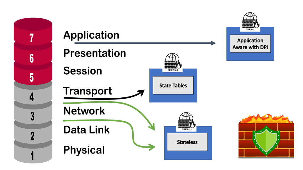
data center firewall
Diagram: The data center firewall.

Implementing Zero Trust & Microsegmentation

Micro-segmentation is a fundamental component of implementing a zero-trust network. It divides the network into smaller, more manageable, and secure zones, enabling organizations to precisely regulate data flow between different sectors of the network.

Zero trust emphasizes verification over blind trust, which requires this level of control. Regardless of the network environment, each segment is subject to strict access and security policies.

Microsegmentation enables the following capabilities:

  1. Due to their isolation and relatively small size, segments can be closely monitored because they are more visible.
  2. By defining associated policies, granular access control is possible.

Micro-segmentation is crucial to mitigating the risk of threats spreading within the network in today’s ever-growing threat landscape. It prevents breaches from spreading and causing broader compromises by isolating them to specific segments. Micro-segmentation enables organizations to manage and secure diverse network environments with a unified framework as they adopt hybrid and multi-cloud architectures.

Key Technology – Software-defined Perimeter

Logically air-gapped, dynamically provisioned, on-demand software-defined perimeter networks minimize the risk of network-based attacks and isolate them from unsecured networks. Drop-all firewalls enable SDPs to enhance security by requiring authentication and authorization before users or devices can access assets concealed by the SDP system. SDP also restricts connections into the trusted zone based on who may connect, from what devices to what services and infrastructure, and other factors.

zero trust

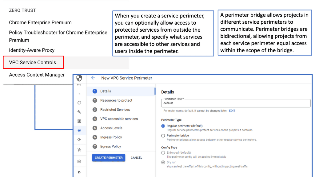
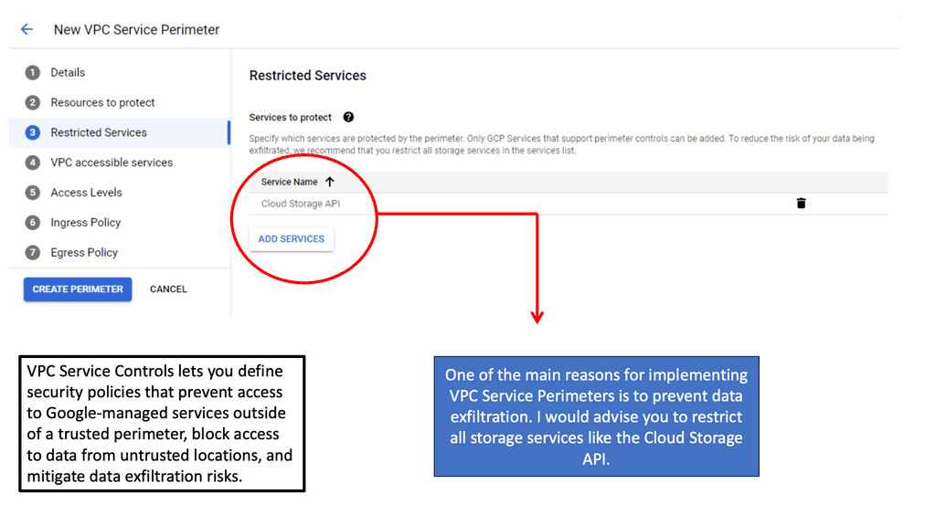
SDP with VPC Service Controls

### Understanding VPC Service Controls

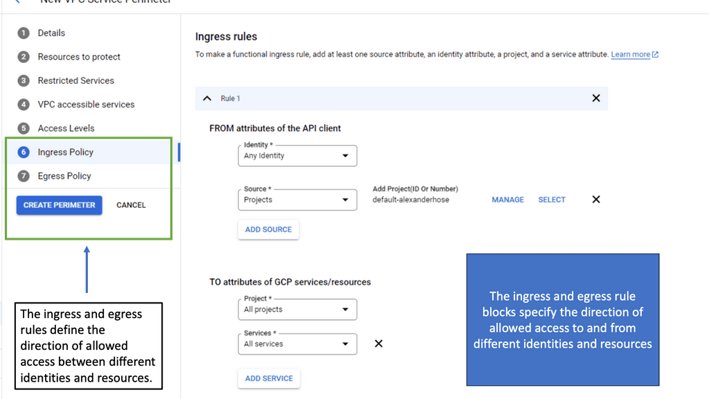
VPC Service Controls offer an additional layer of security for your Google Cloud resources by defining a security perimeter around your services. This feature is particularly valuable in preventing data exfiltration, ensuring that only authorized access occurs within specified perimeters. By creating these controlled environments, organizations can enforce stricter access policies and reduce unauthorized data transfers, a critical concern in today’s data-centric world.

### The Role of Microsegmentation

Microsegmentation is a security technique that involves dividing a network into smaller, isolated segments to enhance control over data traffic. When integrated with VPC Service Controls, microsegmentation becomes even more powerful. It allows for granular security policies that are not just based on IP addresses but also on identity and context. This synergy ensures that each segment of your cloud environment is independently secure, minimizing the risk of lateral movement by potential attackers.

### Implementing VPC Service Controls in Google Cloud

Setting up VPC Service Controls in Google Cloud is a straightforward process that begins with defining your service perimeters. These perimeters act as virtual boundaries around your cloud resources. By leveraging Google Cloud’s comprehensive suite of tools, administrators can easily configure and manage these perimeters. The integration with Identity and Access Management (IAM) further strengthens these controls, allowing for precise access management based on user roles and responsibilities.

VPC Security Controls VPC Service Controls


IPv6 Data Center Microsegmentation

When examining a technology insight for microsegmentation, we can consider using IPv6 for the data center network microsegmentation. Datacenter micro-segmentation techniques vary depending on the data center design requirements. However, the result will be more or less the same with your technique.

Network microsegmentation is a network security technique that enables security architects to logically divide the data center into distinct security segments down to the individual workload level, then define security controls and deliver services for each segment. In this technology insight for microsegmentation, we will address IPv6 micro-segmentation. 

**Implementing IPv6 Microsegmentation: Best Practices**

Successfully deploying IPv6 microsegmentation requires careful planning and execution. Organizations should begin by conducting a thorough assessment of their existing network infrastructure to identify areas that would benefit most from segmentation. It’s crucial to define clear segmentation policies and ensure that they align with the organization’s overall security strategy. Additionally, leveraging automation tools can help streamline the implementation process and ensure that segmentation policies are consistently applied across the network.

**Overcoming Challenges in IPv6 Microsegmentation**

Despite its many advantages, implementing IPv6 microsegmentation can present certain challenges. One of the main obstacles is the need for adequate training and expertise to manage the more complex network configurations that come with microsegmentation. Organizations may also face difficulties in integrating microsegmentation with existing network infrastructure and security tools. To overcome these challenges, it’s essential to invest in training and seek out solutions that offer seamless integration with current systems.

A Key Consideration: Layer-2 Security Issues

When discussing our journey on IPv6 data center network microsegmentation, we must consider that Layer-2 security mechanisms for IPv6 are still as complicated as those for IPv4. Nothing has changed. We are still building the foundation of our IPv6 and IPv4 networks on the same forwarding paradigm, relying on old technologies that emulate thick coaxial cable, known as Ethernet. Ethernet should be limited to where Ethernet was designed: the data link layer between adjacent devices. Unfortunately, the IP+Ethernet mentality is tightly coupled with every engineer’s mind.

Recap on IPv6 Connectivity

Before you proceed, you may find the following helpful post for pre-information.

  1. Zero Trust Security Strategy
  2. Zero Trust Networking
  3. IPv6 Attacks
  4. IPv6 RA
  5. IPv6 Host Exposure
  6. Computer Networking
  7. Segment Routing

Technology Insight For Microsegmentation

Securing Networks with Segmentation 

Securing network access and data center devices has always been a challenging task. The new network security module is Zero Trust (ZT); it is a guiding concept that indicates the network is always assumed to be hostile and external and internal threats always exist. As a result, the perimeter has been moved closer to the workload.

Zero Trust mandates a “never trust, always verify, enforce least privilege” approach, granting least privilege access based on a dynamic evaluation of the trustworthiness of users and their devices and any transaction risk before they can connect to network resources. A core technology for zero Trust is the use of microsegmentation.

  • Enhanced Security

One of the key benefits of microsegmentation is its ability to enhance network security. Organizations can isolate critical data and applications by segmenting the network into smaller parts, limiting their exposure to potential threats. In a security breach, microsegmentation prevents lateral movement, containing the attack and minimizing the possible impact. This fine-grained control significantly reduces the attack surface, making it harder for cybercriminals to infiltrate and compromise sensitive information.

  • Improved Compliance

Compliance with industry standards and regulations is a top priority for organizations operating in heavily regulated industries. Microsegmentation plays a crucial role in achieving and maintaining compliance. By isolating sensitive data, organizations can ensure that only authorized individuals have access to it, meeting the requirements of various regulations such as the General Data Protection Regulation (GDPR) and the Health Insurance Portability and Accountability Act (HIPAA). Microsegmentation provides the necessary controls to enforce compliance policies and protect customer data.

  • Efficient Resource Utilization

Another advantage of microsegmentation is its ability to optimize resource utilization. Organizations can allocate resources more efficiently based on specific requirements by segmenting the network. For example, critical applications can be assigned dedicated resources, ensuring their availability and performance. Additionally, microsegmentation allows organizations to prioritize network traffic, ensuring mission-critical applications receive the necessary bandwidth while less critical traffic is appropriately managed. This efficient resource allocation leads to improved performance and reduced latency.

  • Simplified Security Management

Contrary to what one might expect, microsegmentation can simplify security management for organizations. With a traditional security approach, managing complex network policies and access controls can be challenging, especially as networks grow in size and complexity. Microsegmentation simplifies this process by breaking the network into smaller, more manageable segments. Security policies can be easily defined and enforced at the segment level, reducing the complexity of managing security across the entire network.

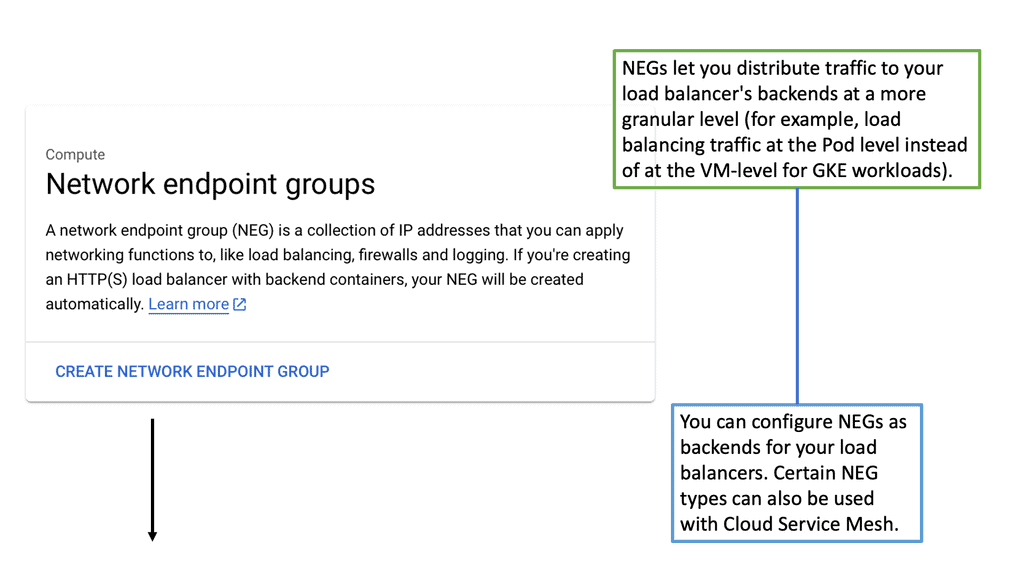
Example Technology: Network Endpoint Groups

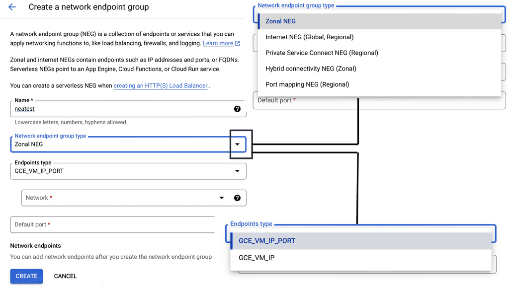
**Implementing NEGs for Enhanced Segmentation**

To harness the full potential of NEGs, it’s essential to implement them strategically within your Google Cloud environment. Start by identifying the endpoints that require segmentation and determine the criteria for grouping them. This could be based on geographical location, application function, or security requirements. Once grouped, configure your load balancing settings to utilize NEGs, ensuring that traffic is directed efficiently and securely.

Additionally, regularly review and update your NEG configurations to adapt to changing network demands and security threats. This proactive approach ensures that your infrastructure remains optimized and resilient against potential disruptions.

network endpoint groups

Data Center Micro-Segmentation

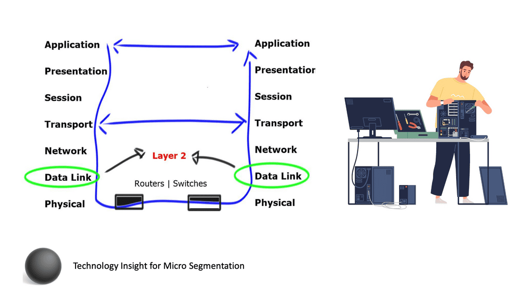
What is Layer 2? And why do we need it? Layer 2 is the layer that allows adjacent network devices to exchange frames. Every layer 2 technology has at least three components:

  1. Start-of-frame indication.
  2. End-of-frame indication.
  3. Error correction mechanism in case the physical layer cannot guarantee the error-free transmission of zeroes and ones.

data center network microsegmentation

**A Key Point: Layer 2 MAC address**

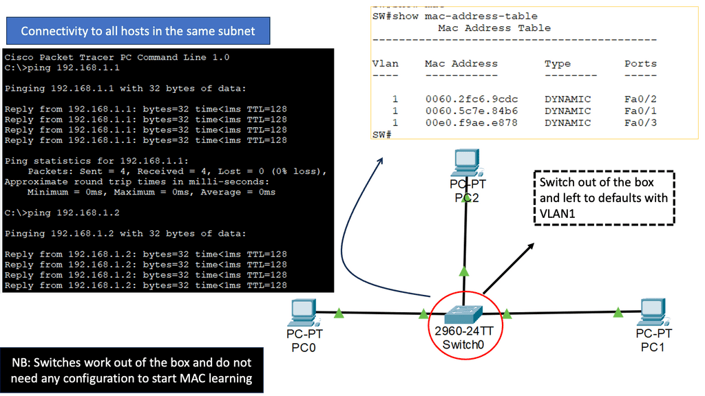
You may have realized I haven’t mentioned the layer 2 MAC address as a required component. MAC addresses are required when more than two devices are attached to the same physical network. MAC addresses are in Ethernet frames because the original Ethernet standard used a coax cable with multiple nodes connected to the same physical medium.

Therefore, layer 2 addressing on point-to-point Fiber Channel networks is not required, while you need layer 2 addressing on shared cable-based Ethernet networks. One of the main reasons for the continuation of MAC addresses in Ethernet frames is backward compatibility. More importantly, no one wants to change device drivers in every host deployed in a data center or Internet.

Technology Insight for Microsegmentation and IPv6

 “IPv6 microsegmentation is an approach used to solve security challenges in IPv6.”

Firstly, when discussing data center network microsegmentation, with IPv6 micro-segmentation, we have many layer-2 security challenges. Similar to the IPv4 world, the assumption is one subnet is one security zone. This can be represented as a traditional VLAN with a corresponding VLAN ID or a more recent technology of VXLAN with a corresponding VXLAN ID.

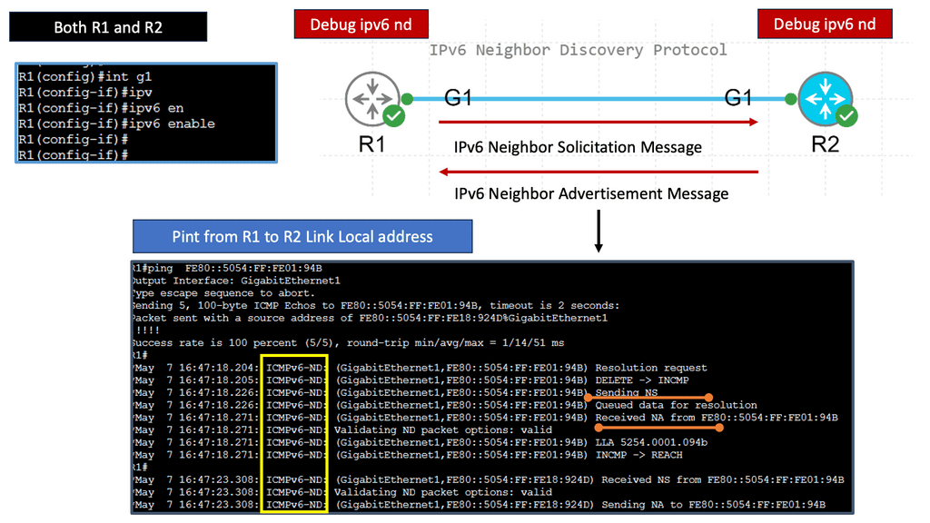
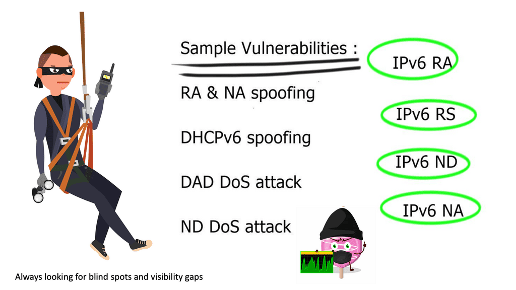
Devices in that domain are in one security domain, and all enjoy the same level of trust, representing several IPv6 security challenges. If intruders break into that segment, they can exploit that implicit trust between all devices. The main disadvantage is that intra-subnet communication is not secured, and multiple IPv6 first-hop vulnerabilities ( RA and NA spoofing, DHCPv6 spoofing, DAD DoS attacks, and ND DoS attacks).

IPv6 security
Diagram: IPv6 security.

A review of IPv6 security

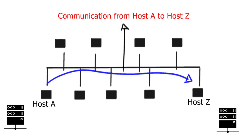
– The attacker can spoof the neighbor advertisement messages and affect the ND cache on the host. Thus, it takes over and intercepts traffic sent to other hosts. It can also intercept DHCP requests and pretend to be a DHCP server, redirecting traffic to itself or DoS attacks with incorrect DNS records. The root cause is that everything we operate on today simulates the thick coaxial cable we use for Ethernet. In the early days, Ethernet segments had one coaxial cable segment, and all stations could attach to this segment, resulting in one large security domain. Networks evolved, and new technologies were introduced. 

– The coaxial cable was later replaced with thin cable and hubs to switches. Unfortunately, we haven’t changed the basic forwarding paradigm we used 40 years ago. We still emulate thick coaxial cable while relying on the same traditional basic forwarding paradigm. The networking industry is trying to fix the problem without addressing and resolving the actual source of the problem.

– The networking industry is retaining the existing forwarding paradigm while implementing a layer-2 security mechanism to overcome its limitations. All these layer-2 security measures ( first-hop security ) lead to complex networks from design and operational aspects. They are adding more kludges; hence, every technology tries to fix the shortcomings when they should be addressing the actual source of the problem.

data center micro segmentation

In the layer 2 world, everyone tries to retain the existing forwarding paradigm, even with the most recent data center overlay technologies. For example, they are still trying to emulate the thick coaxial cable over the VXLAN segment over IP. VXLAN uses historic flooding behavior. In the IPv6 world, to overcome shortcomings with layer 2, vendors started implementing a list of first-hop layer-2 security mechanisms. Implementing these to secure the layer 2 IPv6 domain would be best.

Note: Multicast Listener Discovery Protocol

All these features are complicated technologies to implement. They are used solely to fix the broken forwarding paradigm of layer 2—recent issues with MLD ( multicast listener discovery protocol ), which is part of IPv6. MLD can break into multicast streams on Local Area Networks ( LAN ) and gain control of first-hop router communication.

So, in the future, we will need to implement MLD guard as a new first-hop security mechanism. The list goes on and on—a constant cat-and-mouse game. So, we need to ask ourselves whether we can do better than that. And what can we implement or design to overcome these shortcomings? Just get rid of layer 2? :

Note: Can we Remove Layer 2? 

We can remove layer 2 from “some” networks. If the first-hop router is a layer 3 device, we don’t need to implement all the security kludges mentioned above. However, as end hosts have Ethernet cards, we would still need Ethernet between the end host and router. Using a layer 3 device as the first hop immediately removes all IPv6 spoofing attacks.

For example, RA Gaurd is unnecessary as the router will not listen to RA messages. ND spoofing is impossible as you can’t bridge ND across segments. However, DoS attacks are still possible. This layer 3-only design is implemented on xDSL and Mobile networks—designed by putting every host in a /64 subnet. But; now, we are returning to 64-bit segments to implement security between segments.

  • Is this possible to use in the data center when moving VMs across mobility domains?

Technology Insight For Microsegmentation

IPv6 micro-segmentation for the data center

In data centers, we have issues with live VM migration. We must move VMs between servers while retaining IPv6 addresses to keep all Transmission Control Protocol ( TCP ) sessions intact. Layer 3 solutions exist but are much slower ( as layer 3 routing protocol convergence is slower than layer 2 convergence ) than we can get with simple flooding of MAC address with reverse Address Resolution Protocol ( ARP ) and gratuitous ARP.

Note: VXLAN Segments 

We usually have some VLAN that spans the domain with an actual VLAN or VXLAN segment. VLANs must span the entire mobility domain, expanding the broadcast domain throughout the network. Expanding the broadcast domain also broadens the scope of layer 2 security attacks. Private VLANs exist, but on a large scale, private VLANs are messy and complex.

You can use one VLAN per VM, which would cause an explosion of VLAN numbers. You still need to terminate layer 3 on Core switches, meaning all traffic between two VM must traverse to Core. Inter-VLAN communication is sent to Core ( layer 3 devices) even when the VM sits on the same hypervisor. Not a good design.

Also, if you want mobility across multiple core switches, you can’t aggregate traffic and must pass the IPv6 prefixes to support VM mobility. Now, we have loads of /64 prefixes in the IPv6 forwarding table when using one prefix per VM. Vendors like Brocade only support 3k IPv6 prefixes, and Juniper supports up to 1k. In the future, this scale limitation will represent design problems. So, do we need some other type of design? We need to change the forwarding paradigm. In an ideal world, use layer-3 only networks, layer-3 devices as first-hop devices, and still support VM mobility. At the same time, it does not generate many IPv6 prefixes.

Intra-subnet ( host route ) layer 3 forwarding

Is it possible to design and build layer-3-only IPv6 networks without assigning a /64 prefix to every host?

Intra-subnet layer 3 forwarding implements /128 for hosts, which is propagated with updates across the network. At a host level, nothing changes. It can use DHCP or other mechanisms to get its address. Now that we are using /128, we don’t need to use the IPv6 forwarding table for this prefix. Instead, we can put the /128 into IPv6 Neighbor Discovery ( ND ) entries.

This is how the ND cache is implemented on hardware-based platforms. There is no difference between ND entities and 128-host routes in the IPv6 routing table. The critical point is that you can use ND entries instead of the IPv6 forwarding table, which, by default, has small table sizes on most platforms.

For example, the Juniper EX series can have 32k ND entities but only 1K IPv6 entries. This design trick can significantly increase the number of hosts under an IPv6 microsegmentation design.

Cisco dynamic fabric automation ( DFA )

Virtual Machine microsegmentation with Cisco DFA allows you to implement a VLAN per VM addressing scheme without worrying about VLAN sprawl and all those problems experienced with provisioning. More importantly, all layer 3 traffic is not terminated on the core switch but on the leaf switch. 

Closing Points: IPv6 Microsegmentation

While the benefits of IPv6 microsegmentation are clear, implementing it is not without challenges. Organizations must consider the complexity of transitioning from IPv4 to IPv6, which may require substantial changes to existing infrastructure. Additionally, developing effective segmentation policies requires a deep understanding of the network’s topology and traffic patterns. However, with careful planning and execution, these challenges can be overcome, paving the way for a more secure and efficient network environment.

In conclusion, IPv6 microsegmentation represents a significant leap forward in network security and management. By combining the advanced features of IPv6 with the precision of microsegmentation, organizations can build a resilient, scalable, and secure network infrastructure that meets the demands of the modern digital landscape. As we move towards a more connected world, embracing these technologies will be crucial in staying ahead of the curve and protecting our digital assets.

Summary: Technology Insight For Microsegmentation

In today’s interconnected world, network security has become a critical concern for organizations of all sizes. The traditional perimeter-based security measures are no longer sufficient to combat the ever-evolving threat landscape. This is where microsegmentation comes into play, offering a revolutionary approach to network security. In this blog post, we will delve deep into the concept of microsegmentation, its benefits, implementation strategies, and real-world use cases.

What is Microsegmentation?

Microsegmentation is a network security technique that divides the network into smaller, isolated segments to enhance security and control. Unlike traditional network security approaches, which rely on perimeter defenses, microsegmentation operates at the granular level. It enables organizations to define security policies based on specific criteria such as user roles, applications, and workloads, allowing for fine-grained control over network traffic.

The Benefits of Microsegmentation

Microsegmentation offers many benefits to organizations seeking to strengthen their network security posture. First, it limits the lateral movement of threats within the network, making it significantly harder for cyber attackers to traverse laterally and gain unauthorized access to critical assets. Moreover, microsegmentation enhances visibility, allowing security teams to monitor and detect anomalies more effectively. It also simplifies compliance efforts by clearly separating sensitive data and other network components.

Implementing Microsegmentation: Best Practices

Implementing microsegmentation requires careful planning and strategic execution. Firstly, organizations must conduct a comprehensive network assessment to identify critical assets, traffic patterns, and potential vulnerabilities. Based on this assessment, a well-defined segmentation strategy can be developed. To ensure a seamless implementation process, it is crucial to involve all stakeholders, including network administrators, security teams, and application owners. Additionally, leveraging automation tools and solutions can streamline the deployment and management of microsegmentation policies.

Real-World Use Cases

Microsegmentation has gained immense popularity across various industries due to its effectiveness in enhancing network security. In the healthcare sector, for instance, microsegmentation helps safeguard patient data by isolating medical devices and limiting access to sensitive information. Similarly, financial institutions utilize microsegmentation to protect critical assets, such as transactional systems and customer databases. The use cases for microsegmentation are vast, and organizations across industries can benefit from its robust security capabilities.

Conclusion:

Microsegmentation has emerged as a game-changer in network security. By adopting this innovative approach, organizations can fortify their defenses, mitigate risks, and protect their valuable assets from cyber threats. With its granular control and enhanced visibility, microsegmentation empowers organizations to stay one step ahead in the ever-evolving cybersecurity landscape. Embrace the power of microsegmentation and unlock a new level of network security.